This publication shows how you can make a simple transistor modulator with just one transistor.
The circuits presented in this article are similar to signal sampling circuits because simpel non-linear modulation signal processing is similar to sampling. However, those circuits do not allow linear modulation that was used in AM (Amplitude Modulation) radio.
The period of the sampling signal is 100 us. Therefore the frequency is:
f = 1 / T = 1 / 100 us = 1 / 100 * 1000,000 = 1 * 10,000 = 10 kHz
This is ten times the input frequency of 1 kHz. Thus the signals would not overlap in frequency domain.
Step 1: Design the Circuit
Bipolar Junction Transistor Modulator

The Q1 transistor acts a switch and saturates when the pulse signal is 1 V.
MOSFET Transistor Modulator

The MOSFET transistor acts a switch and saturates when the pulse signal is 1 V.
Step 2: Simulations
I used an old PSpice software for simulations:
Bipolar Junction Transistor Modulator

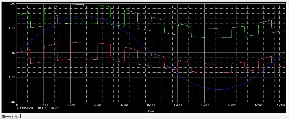
MOSFET Transistor Modulator

The graph above is showing that the MOSFET transistor is not saturating. There must be something wrong with the MOSFET component model in the PSpice software student edition that I used. Usually MOSFET transistors would have a higher voltage current gain than the value specified in the model.
 Simple Circuits
Discussions
Become a Hackaday.io Member
Create an account to leave a comment. Already have an account? Log In.