 Simple Circuits
This article presents a simple power transistor inverter and MOSFET motor driver:

You can see my circuit working in those videos:
Second video:
Step 1: Design the Circuit
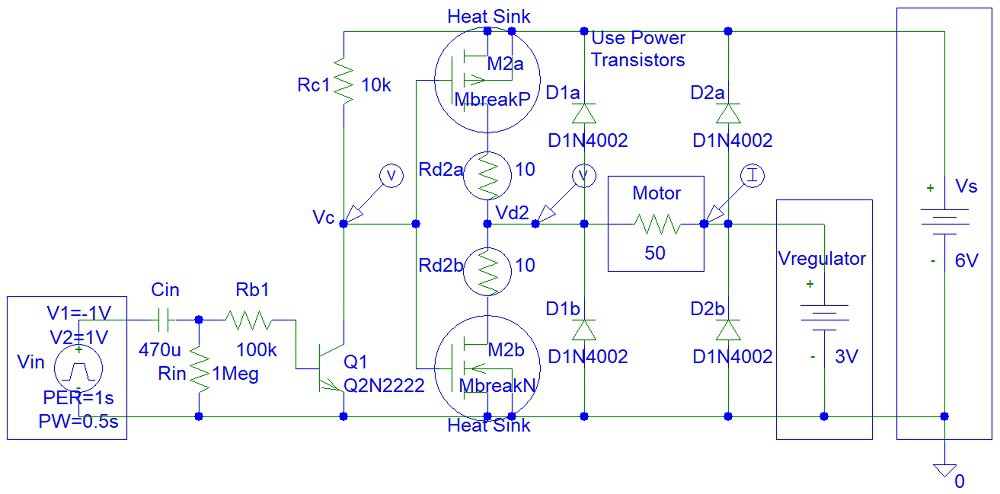
This is my circuit drawn in the old PSpice software:
Later I modified the circuit to work with a Zener diode:

This is a well-known MOSFET motor driver circuit. It is used for MOSFET H-bridge circuits. However, that circuit (H-bridge) might cost more money. You also have to be careful to make sure you do not exceed the maximum gate voltage, the MOSFET input voltage.
You can google MOSFETs on the internet. There is Depletion MOSFET and Enhancement MOSFET. There is a good quote on the internet about the difference between those two types of transistors:
"
- Depletion Type – the transistor requires the Gate-Source voltage, (Vgs) to switch the device “OFF”. The depletion-mode MOSFET is equivalent to a “Normally Closed” switch.
- Enhancement Type – the transistor requires a Gate-Source voltage, (Vgs) to switch the device “ON”. The enhancement-mode MOSFET is equivalent to a “Normally Open” switch.
"
(Source: https://www.electronics-tutorials.ws/transistor/tran_6.html)
I used Enhancement Type MOSFET.
Step 2: Make the Circuit
I used a 3.3 V Zener diode instead of a 4.3 V Zener diode because this is what I had in stock. The use of a voltage regulator will prevent power loss caused by the 100 ohm Rz resistor.

Step 3: Testing
Testing video:
Discussions
Become a Hackaday.io Member
Create an account to leave a comment. Already have an account? Log In.