 Web Photos
I made this circuit many years ago.
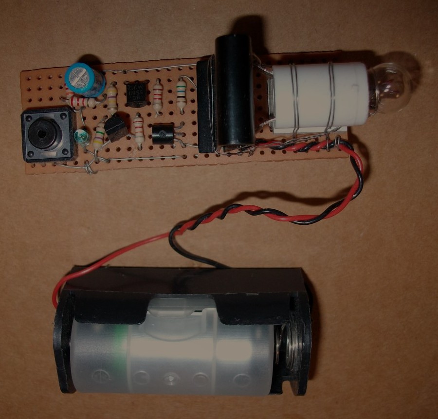
The small green component in the circuit is the photo diode. This photo diode can be modelled as a current source that supplies current when lights are ON.
The light bulb turns ON in the dark for a few seconds. This give you enough time to find a torch that can be used for emergency lighting or go to bed if you are going to sleep. There is also a button shown in the circuit that turns OFF the light bulb earlier to save battery power.
Step 1: Design the Circuit
I drawn the circuit in old PSpice software to save time.
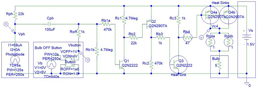
This circuit can be implemented with MOSFET transistors. Rc4a and Rc4b resistors are not essential. You can see I did not use them in my circuit. They are needed for short circuit protection.
I used a 10 uF Cph capacitor for the circuit that you see in the video. However, I specified 100 uF capacitor in the simulations because I considered the option of keep the light bulb ON longer should you choose to make this circuit.
The collector resistors (Rc1, Rc2 and Rc3) and Rb1b are needed to ensure that the transistors OFF when the lights are ON. The collector-emitter pins of each transistor can be modelled as open circuit when Vbe (base-emitter) voltage or input base current are zero. Thus without the collector resistors (Rc1, Rc2 and Rc3), the input of connected/cascaded transistor will be disconnected. However, you can see that my circuit is still working without those resistors.
When lights are OFF, Vph voltage is almost equal to supply voltage, Vs and discharging the Cph capacitor will turn OFF the light bulb.
Calculate the Cph capacitor charge time when lights are OFF with the button:
(the Cph capacitor can be considered fully discharged after 5 time constants)
Tcph2 = 5*Cph*(Roff + Rph) = 11.5 seconds
Calculate the Cph capacitor charge time when lights are OFF without the button:
Tcph2 = 5*Cph*((Rb1a*Rb1b)/(Rb1a + Rb1b) + Rph)
= 5*44.9272727273 seconds = 224.636363636 seconds
(later the simulations will show that the light bulb turns OFF only a few seconds after the first time constant (not five time constants) because the transistors need minimum current input to keep the light bulb ON)
When lights are ON, Vph voltage is zero and discharging the Cph capacitor will turn OFF the light bulb. However, the Cph capacitor could be already zero if the lights were OFF for a long time.
Calculate the Cph capacitor discharge time when lights are ON with the button:
Tcph2 = 5*Cph*Roff = 0.5 seconds
Calculate the Cph capacitor charge time when lights are OFF without the button:
Tcph2 = 5*Cph*((Rb1a*Rb1b)/(Rb1a + Rb1b))
= 5 * (100*10^-6) * 427,272.727273 ohms
= 5*42.7272727273 seconds = 213.636363636 seconds
Calculate the equivalent Rc4 resistance:
Rc4eq = (Rc4a * Rc4b) / (Rc4a + Rc4b) = (1 ohms) * (1 ohms) / (1 ohms + 1 ohms)
= 1 / 2 = 0.5 ohms
Rc4a and Rc4b can be replaced with one 0.5 ohm resistor. I used two resistors to reduce the power dissipation for each resistor.
Calculate the potential voltage across the Rc4 and Rc4b resistors:
Vrc4 = Rc4eq * Ibulb
= 0.5 ohms * 0.3 A = 0.15 V
This means that the 1.5 V light bulb is receiving a voltage of:
Vbulb = Vs - Vcr4 = 1.5 V - 0.15 V = 1.35 V
Calculate the power dissipation for Rc4a and Rc4b resistors:
Prc4eq = Vrc4 * Ibulb = 0.15 V * 0.3 A
= 0.045 W = 45 mW
Thus each resistor (Rc4a and Rc4b) will dissipate: 45 mW / 2 = 22.5 mW
Calculate the minimum transistor Q4 current gain to ensure saturation:
BetaMin = ((Vs - VQ4sat) / (Rbulb + Rc4a/2)) / ((Vs - Vbe - VQ3sat) / Rb4)
= ((1.5 V - 0.2 V) / (5 ohms + 0.5 ohms)) / ((1.5 V - 0.7 V - 0.2 V) / 47 ohms)
= (1.3 V / 5.5 ohms) / (0.6 V / 47 ohms) = 18.5151515152
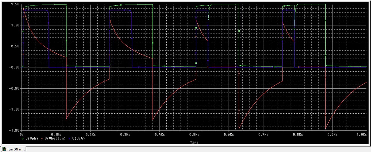
Step 2: Simulations
Simulations shows two cycled without the OFF button and two cycles with the OFF button:
Discussions
Become a Hackaday.io Member
Create an account to leave a comment. Already have an account? Log In.