Hey Guys!! Do you want to Calibrate APM 2.8 using Mission Planner? I am here to provide you a simple path to do it. You can start by using the following parts:
FlySky FS-i6 2.4G 6CH PPM RC Transmitter With FS-iA6B Receiver
Q450 Quadcopter Frame — PCB Version Frame Kit with Integrated PCB
2212 920KV Brushless DC Motor for DJI
DYS 30A Brushless Speed Controller ESC
Orange 3000mAh 3S 40C/80C Lithium polymer battery Pack (LiPo)
Step 1 — Install Mission Planner and Connecting with APM
You can download Mission Planner from: http://ardupilot.org/planner/docs/mission-planner-installation.html
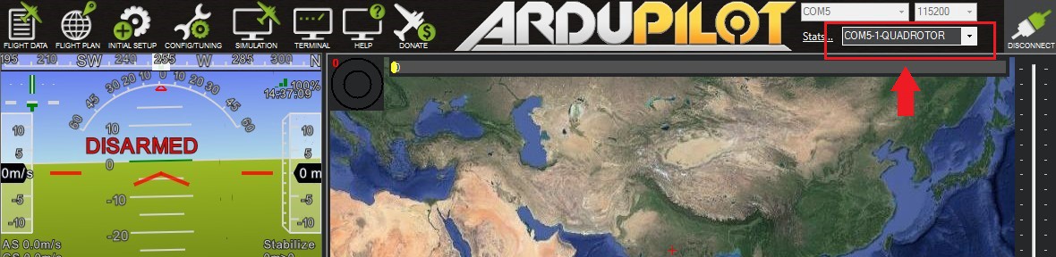
It can be used to Program APM and Pixhawk flight controllers. Now connect Your APM flight controller to PC using USB to MicroUSB cable, a Green led will light up and Red led will start blinkingPC will detect the Bordas “Arduino Mega” and will automatically install the required drivers. Open Mission Planner software and select proper COM port on the top right corner and select the baud rate at 115200. Don’t select on connect yet on the top right corner.
Now go to the “INITIAL SETUP” tab and click on “Install Firmware” and then select the type of Multirotor setup. Here we will be selecting a Quadrotor setup. Proceed further by giving further permissions and the firmware update will start.
It will take 2–3 minutes to boot the Firmware to the APM board ( Make Sure your PC is connected to the internet as it will be downloading some required files). After completion, click on the CONNECT on the top right corner of the window to connect the APM board to the PC. Now it will show the Device as “Quadrotor”

Step 2 – Calibrate Compass and Accelerometer
Now again go to the Initial Setup tab and click on Mandatory Hardware.
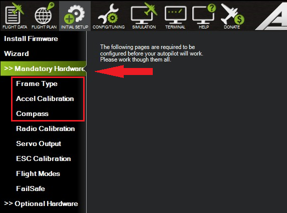
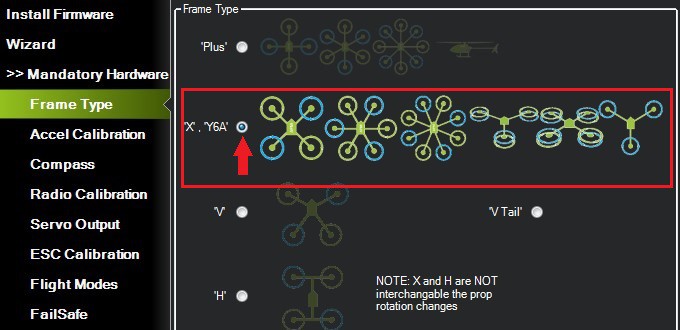
Firstly, select on frame type, and select the X type of frame for your Drone.
Now go to the Accel Calibration Section and click on Calibrate Accel.
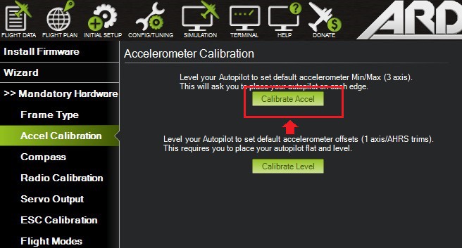
Follow the instructions as shown on-screen and perform the same to calibrate the Accelerometer. After finishing the accelerometer calibration, you can head for a compass calibration.APM 2.8 has a built-in compass, hence no need for an external compass. Just head on to Live Calibration and Start rotating your APM 360 degree
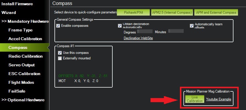
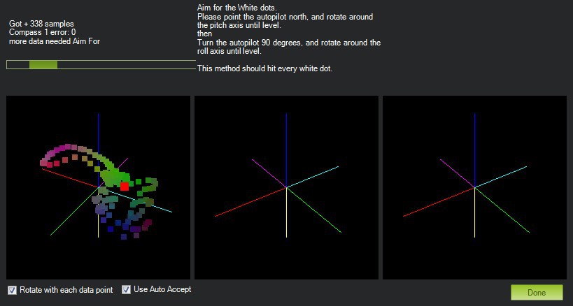
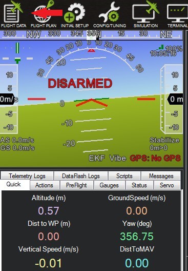
Click on finish, when done. You can also view it graphically by going to the flight data tab on the top right corner. Move the APM while it is connected to Mission Planner. You will see the change in the position of flight and corresponding values also.
Step 3 — Connect and Calibrate Radio Control
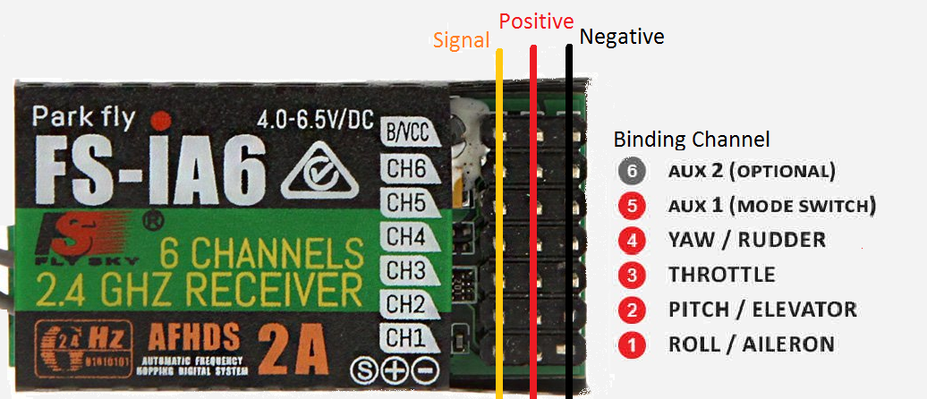
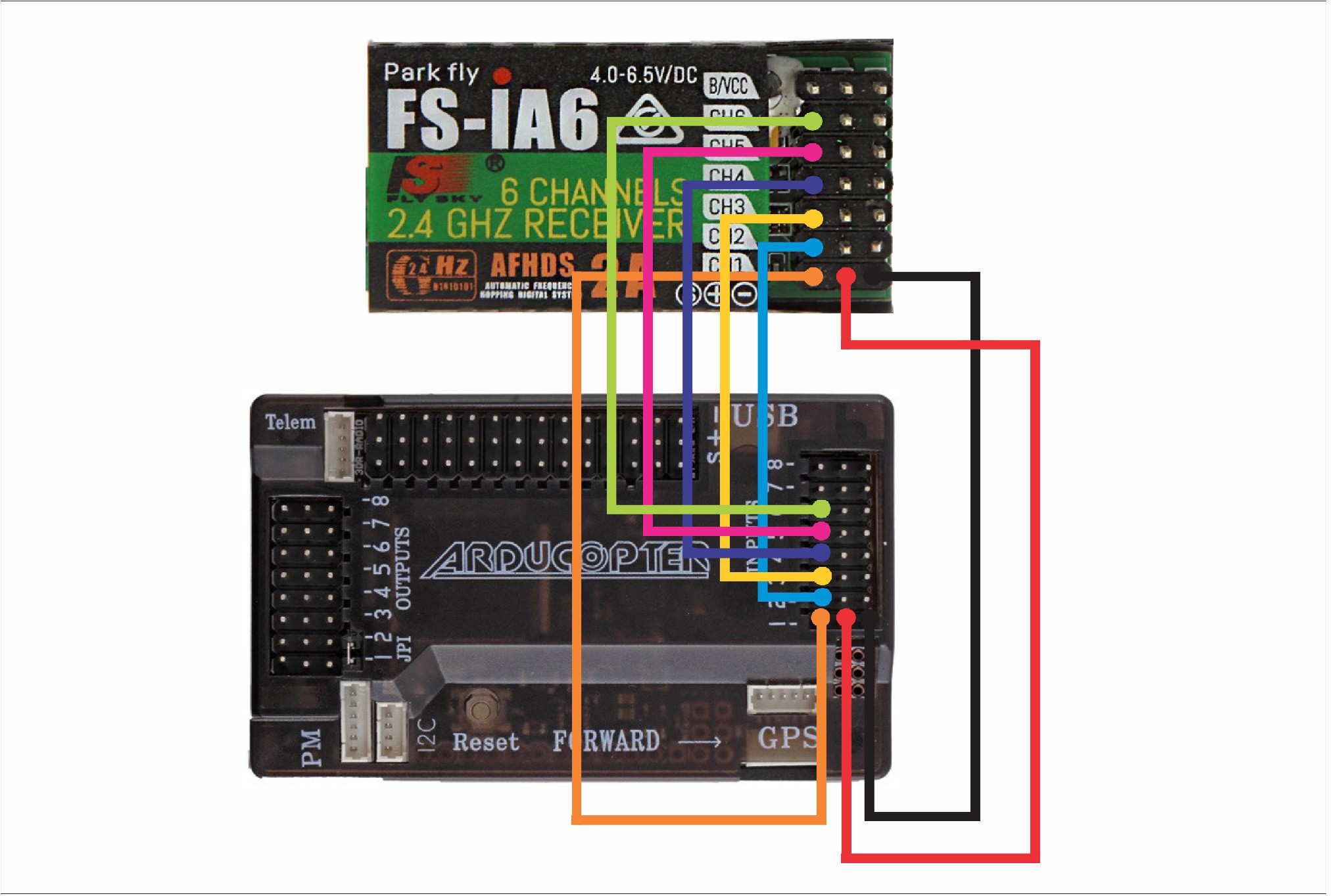
For this, we will have to connect Reciever to the Flight Controller.The Pin Configuration of Input side of APM (Which is to be connected to APM) and configuration of Reciever FS-iA6 is as shown. APM 2.5, 2.6, 2.8 all have similar configuration. Here the outermost pin is Ground, Middle pin is for Positive supply and the innermost pin is Singnal Pin.Ideal way to connect various channels with reciever is also shown.
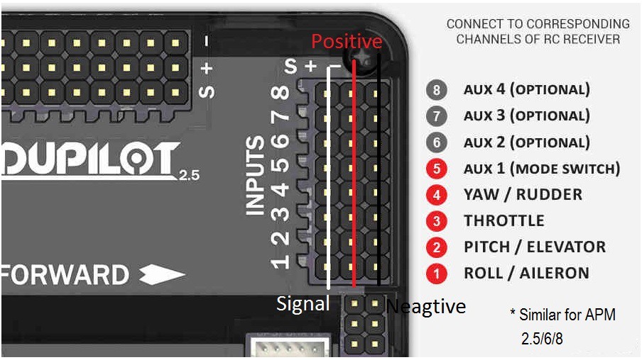
Below is the PinOut for the Reciever FS-iA6. First channel is for ROLL/AILERON,Second is for PITCH/ELEVATOR, Third is for THROTTLE, Fourth is for YAW/RUDDER and fifth and sixth are Mode selection switch. Here also, outer one is Negative switch, middle one is Positive switch and the left one or innermost one is signal pin. Channel wise setup is similar in other 6 Channel Recievers also.
Now Connecting the receiver with the transmitter. Here we will be connecting APM with Reciever.
Now since the Connection is done, a red light will glow up in the Receiver. Make sure, that the Reciever is binded with Transmitter. If it isn’t binded, you can view this video to how to bind — https://www.youtube.com/watch?v=9-Z0rTVEkHI
Now go to the Radio Calibration section in the Mandatory Hardware part.
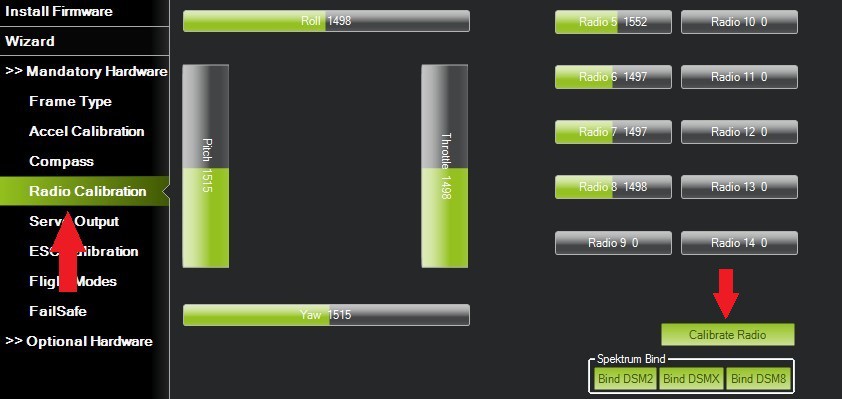
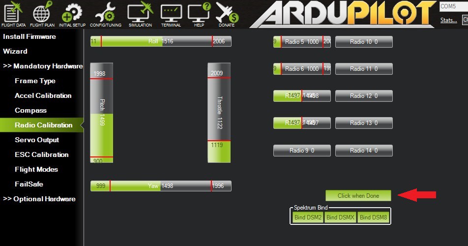
You will see different bars for different parameters. Now if you change the position of any stick on the transmitter’s joystick, the bar for corresponding parameter will change.Click on the calibrate radio button and vary all the parameters between its extreme ends. Move joystick in all direction upto extreme ends and also change the position of knobs to extreme. You will now notice that Red extreme lines will be captured by the Mission Planner for the corresponding channels. Now since the extremes will be captured by software, click on the “click when done button” to save the same.
Now the calibration is done, and your APM is now programmed to fly.
This project is based on an article Calibrating APM 2.8 using Mission Planner— By Abhishek Thakur.
Visit the article to know more about it.
Discussions
Become a Hackaday.io Member
Create an account to leave a comment. Already have an account? Log In.