 max
maxIn Part 5 of this soon-to-be-epic series of articles. We introduced components called resistors. Also, we discussed the concept of Ohm’s law, which describes the relationship between voltage (V), current (I), and resistance (R).
Later, in Part 6, just for giggles and grins, we added the concept of power, and we noted that when we are designing electrical and electronic circuits, it’s important to do the math before we flip the power switch to its “On” position, otherwise we may find ourselves living in interesting times.
Thus far, we’ve considered a simple circuit with only one resistor, but it’s common to have two or more of these little rascals. One way we can connect resistors is in “series,” i.e., one after the other as illustrated below:
 Two resistors connected in series (Image source: Max Maxfield)
 Now, one thing that often confuses beginners is why we typically only draw one annotated arrow for the current (I) as shown in (a) in the figure above. Why don’t we show multiple annotated arrows as shown in (b) in the figure above? Furthermore, in the same way that we use labels like R1 and R2 for our resistors, why don’t we use labels like I1, I2, and I3 for the currents?
The reason for this is that, in a circuit in which all the parts are connected in series, the current is the same wherever we measure it. In our example circuit, we have the power source (the battery in this case) connected to resistor R1, which is connected to resistor R2, which is connected back to the battery. Since the current is the same wherever we measure it, we don’t waste our time by indicating it in multiple locations in our circuit diagram.
Unfortunately, this may not be intuitive at first, so let’s look at things another way. An electric current is the rate of flow of electric charge past a given point. Another way of looking at this is that the current is the number of electrons that pass a given point at any particular time. In Part 2, we used a water-based analogy to introduce the concepts of voltage, current, and resistance. Let’s use a variation of this analogy as illustrated below:
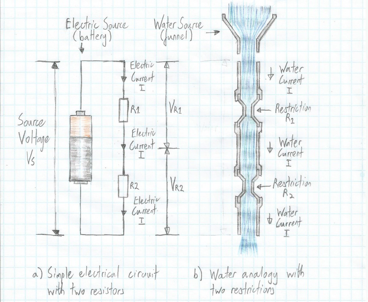 A water analogy for two resistors connected in series (Image source: Max Maxfield)
 In this case, we are envisaging a vertical pipe with two restrictions, where these restrictions are intended to represent the resistors in our electrical circuit. Now, all analogies are suspect, and this one doubly so, but I think it gets the point across. The idea is that, irrespective of any restrictions in the pipe, whatever amount of water goes in at one end (from the funnel in this example), the same amount of water comes out of the other. Furthermore, at whatever points we decide to measure the flow, the same amount of water is passing those points at any particular time (it may go faster through the restrictions and slower in the main pipe, but it’s the same volume per second wherever we measure it).
Let’s take another look at the image above. Observe that we show the voltage source as being Vs (we don’t care as to its actual value at the moment). Also, we show voltage drops of Vr1 and Vr2 across resistors R1 and R2, respectively.
If you look in a textbook, you will see that the equations used to determine these voltages are as follows:
Vr1 = Vs/(R1 + R2) * R1
Vr2 = Vs/(R1 + R2) * R2
This is easy enough to remember, but where did these equations magically appear from? You should never be afraid to ask these questions. Also, it’s always useful to be able to derive stuff like this yourself from first principles. In this case, we start with the fact that if we have ‘n’ resistors in series, then the total resistance Rt = R1 + R2 + … Rn. In our case, we have only two resistors, so our total resistance Rt = R1 + R2.
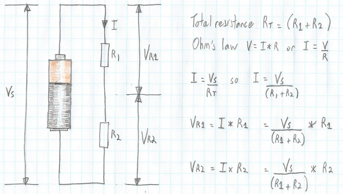 Voltage calculations for two resistors connected in series (Image source: Max Maxfield)
 From Ohm’s law, we know that V = I * R, which means I = V/R. In the case of our circuit, V is Vs and R is Rt, so I = Vs/Rt, which means I = Vs/(R1 + R2).
OK, so, now we know the current (I). We also know that the current is the same at any point in the circuit, which means that the current going through resistor R1 is the same as the current going through resistor R2.
Returning to Ohm’s law, we know V = I * R, which means the voltage across R1, which we will call Vr1, will be I * R1. Even better, we already know that I = Vs/(R1 + R2). Substituting this gives us Vr1 = Vs/(R1 + R2) * R1. We can determine the voltage across resistor R2 in a similar fashion. It goes without saying -- but I'll say it anyway -- that Vs = Vr1 + Vr2.
The end result of these shenanigans is that we can determine the voltage drop across a resistor without actually knowing the current flowing through it. All we need to know is the value of the source voltage and the values of the resistors.
Voltage is also known as “electric potential.” In electronics, a voltage divider (a.k.a. a potential divider) is a circuit that produces an output voltage (Vout) that is a fraction of its input voltage (Vin). “Good golly miss Molly!” If we take our circuit above and add an extra piece of wire between our two resistors to act as an output, then we’ve actually created a voltage divider as illustrated below:
 Using a voltage divider created from two resistors in series (Image source: Max Maxfield)
 In this case, we’ve replaced our power source (the battery) with a sensor in the form of a microphone. Purely for the sake of this example, let’s assume that the output from the microphone is a voltage that can swing between 0 V and 15 V. Let’s also suppose that we wish to feed this signal into a microcontroller, but that the microcontroller’s inputs can only accept signals that range between 0V and 5V.
Before we started this column, this would have been a bit of a conundrum, but now we are masters of the mystic arts regarding resistors in series, so we know that one solution is to create a voltage divider.
The only remaining question is why we used values of 2 kΩ (2,000 ohms) and 1 kΩ (1,000 ohms) in the illustration above for resistors R1 and R2, respectively. To be honest, I just “picked them out of a hat,” as it were. From our equations, we know that -- since we wish Vout to be 1/3 of Vin -- all we need to do is make sure that R1 is twice the value of R2.
If we were creating a real circuit, we would start off by deciding what we wished the maximum current to be. Since we know the maximum voltage (15 V in this case) and we are specifying the desired maximum current, this would allow us to determine the total resistance Rt. In turn, once we know Rt, knowing that R1 = 2 * R2 allows us to calculate the values of R1 and R2.
Purely for the sake of an example, let’s say that we decide our maximum current is to be 1 mA (which is 0.001 A). So, using V = I * R, and remembering that we have to work in units of volts, amps, and ohms, we have Vin = I * Rt, which means Rt = Vin/I, so Rt = 15/0.001 = 15 kΩ. In turn, this means R1 will be 10 kΩ and R2 will be 5 kΩ.
This really isn’t so bad once you start to wrap your brain around it. Next time, we will consider what happens when we wire our two resistors in “parallel,” i.e., side-by-side. Until that frabjous day, as always, I welcome your comments, questions, and suggestions.
Discussions
Become a Hackaday.io Member
Create an account to leave a comment. Already have an account? Log In.
Vr2 = Vout; Vs = Vr1 + Vr2; If r1 = r2 then Vr1 = Vr2; If r1 < r2 then Vr1 < Vr2; Vs is divided up between r1 and r2. Now what part of the whole or total resistance is r1? [r1/(r1+r2)] is that amount. If I is the same V is larger across the larger r. Vr2 = [r2/(r1+r2)]*Vs and Vr1=[r1/(r1+r2)]*Vs
Are you sure? yes | no
"Another way of looking at this is that the current is the number of electrons that pass a given point at any particular time." This seems to imply an instant in time. It must be a time "interval" to measure the number of current carriers. Another case where current must be recognized as a flow-rate not an amount. Okay I'm done beating this horse.
Are you sure? yes | no
Vout=vin/(r1+r2)*r1
Gives different values but since vout is in the middle of two resister r1 and r2, value should be same at that point.
Please clear this doubt.
Are you sure? yes | no