 DIY Electronics
I made the following transistor microphone amplifier circuit:

I modified the circuit shown in this link:
https://www.instructables.com/id/Transistor-Microphone-Amplifier/
You can see my circuit working in this video:
You can see hear Nova's voice in this video promoting Renewable Energy Society events. This website is a project sponsored by the Hobby Community organisation.
Step 1: Design the Circuit
I changed the circuit by reducing the values of the collector resistors and thus reducing the cost:

You only need 1 kohm resistors (not 10 kohm and 1 kohm) and save money by buying in bulk. However, this change increases the transistor power dissipation and will affect the microphone AC signal gain.
I also used a feedback bias instead of a fixed bias to reduce the affect of temperature change on transistor biasing voltages. This change also reduced the circuit gain.
Step 2: Simulations
Transient:

The maximum current is below 10 mA. However, testing showed that the LEDs could still produce bright light.
Frequency:

A typical transistor circuit will not have such long bandwidth unless you are using radio frequency transistors.
Step 3: Make the Circuit
I did not have three NPN transistors. Thus I used a PNP transistor for the LED indicator. I had to flip the indicator circuit upside down:
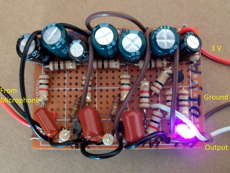
I used smaller LEDs that might have a maximum current of only 5 mA, not 10 mA that was used in the Instructables link:
https://www.instructables.com/id/Transistor-Microphone-Amplifier/
Step 4: Testing
I connected the circuit to USB oscilloscope:

You can see that the average Vl voltage is 2.44 V and not 0 V because I flipped the transistor indicator circuit.
Discussions
Become a Hackaday.io Member
Create an account to leave a comment. Already have an account? Log In.