 max
maxAs noted in our previous column, in the not-so-distant future we’re going to start creating simple circuits using resistors and light-emitting diodes (LEDs), but we first need to learn enough about resistors to ensure we use the right ones when the occasion demands.
Unfortunately, it isn’t realistic for a manufacturer to create a collection of resistors comprising every conceivable value in a cost-effective manner. Furthermore, the people who use resistors couldn’t afford to purchase all of the different values and wouldn’t have the space required to store them if they did.
The solution arrived at by the industry was to adopt a selection of standard values, which has the added advantage of allowing users to second-source their resistors from multiple manufacturers. The real trick was for everyone to agree on the values forming the standard set.
As we discussed in Part 10, in 1877, a French military engineer called Charles Renard proposed a scheme of preferred numbers that allowed the French army to reduce the 425 different sizes of ropes they required to keep their balloons in the air to only 17 sizes that covered the same range.
In Renard's system, the interval from 1 to 10 was divided into 5, 10, 20, or 40 steps, which we now refer to as the R5, R10, R20 and R40 scales.
The E Series of Preferred Numbers
In 1952, the IEC (International Electrotechnical Commission) defined a set of standard values for different types of components, including resistors. Collectively referred to as the “E series,” this actually consists of the E3, E6, E12, E24, E48, E96 and E192 series, where the number after the 'E' designates the quantity of value "steps" in each series.
Let’s start by looking at the E12 series. One way to represent this mathematically is as follows (where the symbol ≈ means “approximately equal to”):
10(0/12) = 1
10(1/12) ≈ 1.2
10(2/12) ≈ 1.5
10(3/12) ≈ 1.8
10(4/12) ≈ 2.2
10(5/12) ≈ 2.7
10(6/12) ≈ 3.3
10(7/12) ≈ 3.9
10(8/12) ≈ 4.7
10(9/12) ≈ 5.6
10(10/12) ≈ 6.8
10(11/12) ≈ 8.2
10(12/12) = 10
Another way we can look at this is graphically as shown below. Since this scheme is based on a logarithmic approach, and since the E12 series employs 12 subdivisions, observe that each new number can be generated by multiplying the previous value by 10(1/12) ≈1.21.
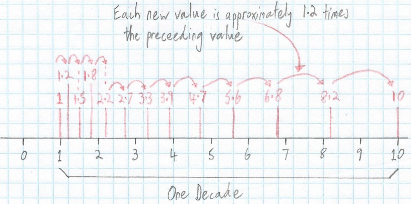 A graphical representation of the E12 scale (Image source: Max Maxfield)
 Remember that these values repeat for every decade, which means we can summarize them in a table as shown below.
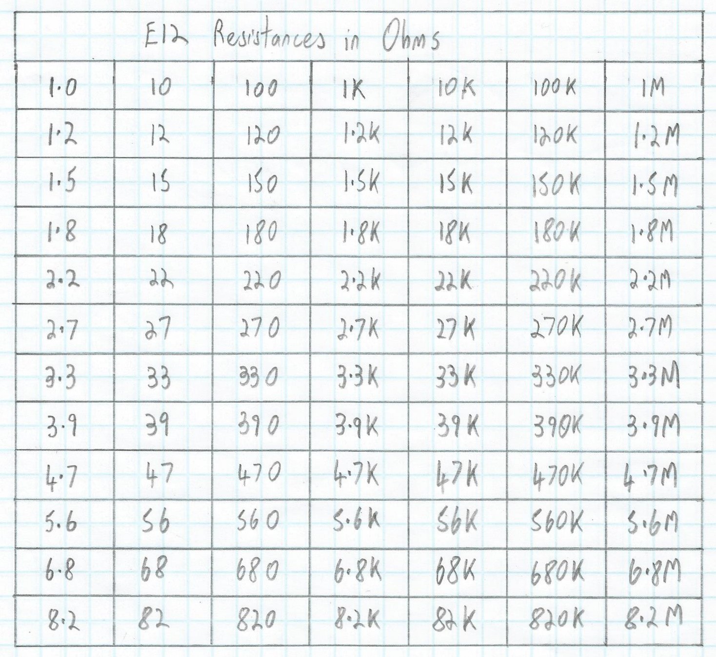 A tabular representation of E12 resistor values (Image source: Max Maxfield)
 Through-Hole vs Surface-Mount
Warning -- incoming abbreviation storm! There are two main ways to attach electronic components to printed circuit boards (PCBs). The first is through-hole technology (THT), which is also known as lead through-hole (LTH). The second is surface-mount technology (SMT), whose components may be referred to as surface-mount devices (SMDs).
In the case of THT, component leads are run through copper-plated holes that pass through the PCB. Solder is then applied to attach the component leads to copper pads associated with the holes. By comparison, in the case of SMT, the SMDs are soldered onto pads on the surface of the board. For the purposes of these columns, we will be working with THT components whose leads we will plug into holes in breadboards (don’t worry; all will become clear when the time is ripe).
Resistor Color Codes
Resistors come in many different shapes and sizes. In these columns, we will primarily be playing with 0.25-watt THT devices whose bodies are about 0.25 inches (6.5 mm) long.
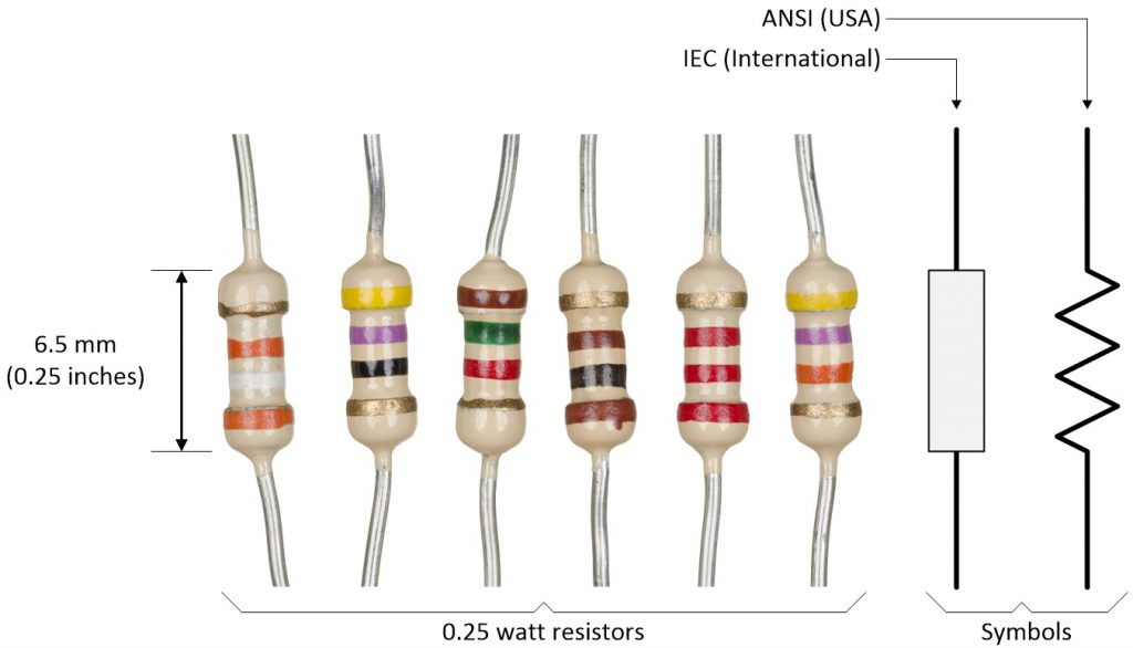 Some 0.25-watt (a.k.a. 1/4 watt) THT resistors and alternative symbols (Image source: Max Maxfield)
 When we say “0.25 watt” or “0.25 W,” we’re talking about the maximum amount of power these devices can handle (we introduced the concept of power in Part 6 of this soon-to-be-epic series).
As shown in the diagram above, there are two symbols that are commonly used for resistors -- the zig-zag line is the ANSI symbol, which is most often seen in the USA, while the rectangular IEC symbol is more commonly employed by an international audience.
Also, observe the colored bands on these components. We use these bands to indicate the resistance value of the part. Some resistors have four colored bands, some have five, and some have six. For the purposes of these columns, we will be working with 4-band resistors. If you look closely, you will see that three of these bands are gathered to form a group, while the fourth is left out on its own. In order to read the value, we orientate the resistor such that the group of three bands is on the left.
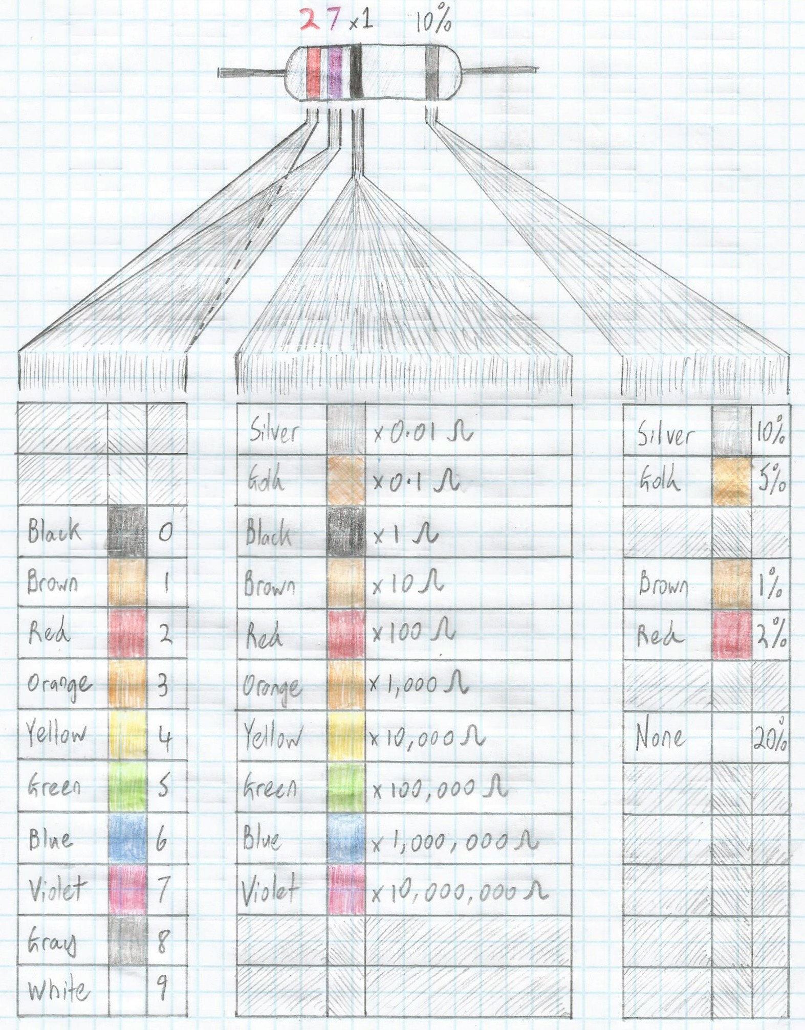 4-band resistor color code (Image source: Max Maxfield)
Reading from left-to-right, the first two bands are used to represent the first two digits of the resistance value. Meanwhile, the third digit is used as a multiplier. Thus, the red (2), violet (7), black (x1) bands in the image above indicate a 27 Ω resistor. By comparison, red (2), violet (7), brown (x10) would indicate 270 Ω; red (2), violet (7), red (x100) would indicate 2,700 Ω, and so forth.
Another way to think of this is that the multiplier band indicates the number of 0s we add onto the end of the first two digits. So, assuming our first two digits are still red (2) and violet (7), a third band of black would indicate that we use zero 0s (i.e., 27 Ω), a third band of brown would indicate we use one 0 (i.e., 270 Ω), a third band of red would indicate we use two 0s (i.e. 2,700 Ω), and so forth. This is the way I tend to think about things, but you can use whichever approach works best for you.
Meanwhile, the band on the right-hand side indicates the tolerance of the device, with brown, red, gold, and silver indicating tolerances of 1%, 2%, 5%, and 10%, respectively (if this band is missing, then we are talking about a 20% tolerance component).
Note that when we say something like 1% tolerance, we mean that the actual value can be ±1% of the nominal value. Let’s take our red, violet, red resistor as an example. Although its nominal value is 2,700 Ω, 1% of this value is 27, which means a 1% tolerance device may have any value between 2,700 – 27 = 2,673 Ω and 2,700 + 27 = 2,727 Ω; a 2% tolerance component may have any value between 2,700 – 54 = 2,646 Ω and 2,700 + 54 = 2,754 Ω; a 5% tolerance part may have any value between 2,700 – 135 = 2,565 Ω and 2,700 + 135 = 2,835 Ω; and a 10% resistor may have any value between 2,700 – 270 = 2,430 Ω and 2,700 + 270 = 2,970 Ω.
Never, Ever...
Actually, things may be a little – let’s say “more interesting” – than you might suppose. How do you think manufacturers create the 1%, 2%, 5%, and 10% versions of these components? I’ll give you a clue, which is that they don’t have separate production lines. What actually happens is that they do their best to hit the target value, but natural process variations result in a standard distribution of values shown as (a) in the image below.
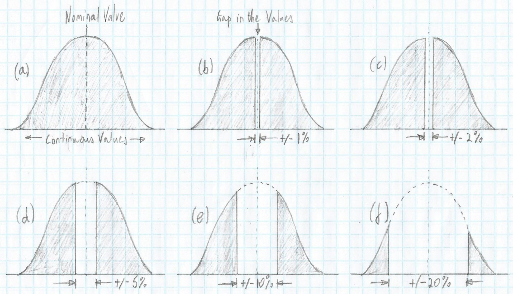 Why 2%, 5%, and 10% tolerance 2,700 Ω resistors are never, ever 2,700 Ω (Image source: Max Maxfield)
 What the manufacturer does is measure each resistor as it rolls off the production line (today, this measuring is performed automatically; in the past, it was done by hand). If they find a part whose value lies between 2,673 and 2,727 ohms, they paint a brown band on it and drop it in the 1% tolerance “bucket.” The result is to leave a “hole” in the distribution curve shown as (b) in the image above.
Next, they remove the 2% resistors, resulting in a bigger “hole” in the distribution curve shown as (c) in the image above. Similarly, for the 5% and 10 % resistors shown as (d) and (e) in the image, and so it goes. In the case of a 5% resistor, for example, the 2% “hole” means that this resistor may have a value between 2,565 (the lower end of the 5% value) and 2,646 (the lower end of the 2% value), or between 2,754 (the upper end of the 2% value) and 2,835 (the upper end of the 5% value). The only things we can say about a 2,700 +/- 5% Ω resistor for sure is that it won’t fall in the 2% range and it will never, ever be 2,700 Ω.
Alternative Nomenclatures
As we’ve seen, it’s common to write values like 2.7 Ω, 2.7 kΩ, and 2.7 MΩ. However, the problem with using decimal points is that they can be easy to miss and/or they can become obscured in printed materials – especially in electrical schematics being used on the factory floor – in which case 2.7 Ω, 2.7 kΩ, and 2.7 MΩ could easily be mistaken for 27 Ω, 27 kΩ, and 27 MΩ respectively.
In order to prevent this, an alternative nomenclature is to use the characters R, K, and M to replace the decimal points; for example, 2R7 is another way of saying 2.7 Ω, 2K7 is another way of saying 2.7 kΩ, and 2M7 is another way of saying 2.7 MΩ.
Below is a new version of our earlier table using this alternative naming convention and showing graphical depictions of the corresponding color bands (I haven't included the tolerance band in these images because I didn't want to confuse the issue).
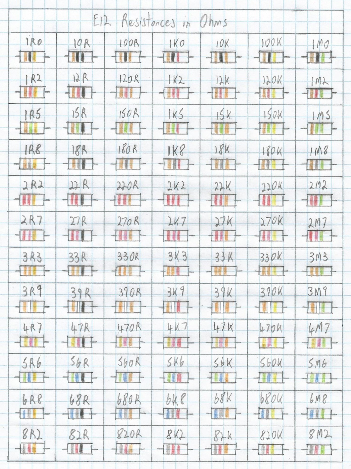 A tabular representation of E12 resistor values using our alternative nomenclature (Image source: Max Maxfield)
 In the not so-distant past, there was a significant difference in price between E12 series (10% tolerance) and E24 series (5% tolerance) resistors. More recently, this price differential has closed to the point of insignificance, at least with regard to the relatively small numbers of components used in hobby projects (even small variations in price are significant if you are building ten million units). Thus, for my hobby projects, I typically use E24 series resistors, which have a tolerance of 5%, but that table would have been too much of a hassle to draw here (you can easily find in by Googling “E24 Resistors”).
Final Thoughts
As we noted in an earlier column, when we design an electronic circuit, we may perform some calculations, wave our hands in the air, perform an interesting dance, and decide that -- in an ideal world -- we would like to use a resistor with a value of exactly X ohms.
The problem is that it’s not often that the exact value we are looking for exists. The solution is to round the calculated resistor value to one of the preferred values. The subdivisions used for the E6, E12, E24, etc. series of preferred numbers ensure that, when some arbitrary value is replaced with the nearest preferred number, the maximum relative error will be in the order of 20%, 10%, 5%, etc., respectively.
Furthermore, in many cases we would round to the closest preferred value. In some cases, however, a better (safer) option is to round up to the closest higher preferred value, even if the closest lower preferred value is, in fact, closer. In the case of a current-limiting resistor, for example, using a preferred value that is lower than our calculated value will increase the current, which may overload our circuit.
Did you notice in the previous paragraph where we said “current-limiting resistor”? In fact, this is just a regular resistor that’s being used in a current-limiting capacity. In certain cases, it’s common to use a qualifying term like “current-limiting,” “pull-up,” and “pull-down” to indicate the role a resistor is playing in the circuit.
In our next column, we will consider different types of multimeters and discuss how to use them to measure the values of our resistors. In the meantime, as always, I welcome your comments, questions, and suggestions.
Discussions
Become a Hackaday.io Member
Create an account to leave a comment. Already have an account? Log In.