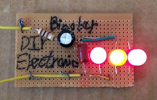
 DIY Electronics
This is a simple frequency light controller:
Video:
Blinking video:
The bipolar capacitor significantly increases the cost of this circuit. Thus you might try using Schottky or typical silicon diodes used in those links:
https://www.instructables.com/Oscillator-LED-Dimmer-1/
https://hackaday.io/page/9679-oscillator-led-dimmer
Step 1: Design the Circuit
I used an old Student Edition of PSpice simulation software to quickly draw the circuit:
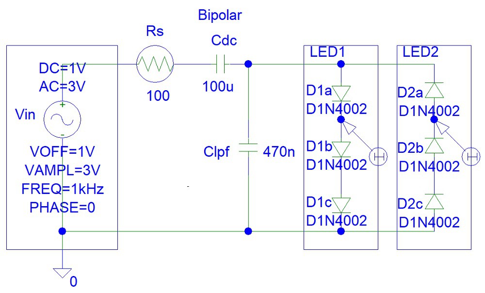
Keep in mind that my circuit does include high voltage protection. Thus you might easily burn your LEDs.
The 100 uF bipolar capacitor is used to remove the DC component of input signal.
At frequencies above 1 kHz the reactance of the 100 uF bipolar capacitor is almost zero:
Xdc = 1 / (2*pi*1000 Hz*(100*10^-6))
= 1.59154943 ohms
The the maximum low pass frequency will equal to:
fl = 1 / (2*pi*(Rs||Rled)*Clpf)
= 1 / (2*pi*(Rs*Rled/(Rs+Rled))*Clpf)
(Where: Rled = Internal resistance of the LED diode (ohms))
Step 2: Simulations
Simulations show that the two LEDs indicate the direction of the current entering the circuit. The two LEDs are never ON at the same time.

You can see how the average LED current eventually settles to zero after about 70 ms. You can reduce the settling time to just 7 ms by reducing the Cdc capacitor value. However, then the LEDs will not be ON at low frequencies.
Step 3: Make the Circuit
I used a soldering iron because I modified the circuit a few times, replacing the 10 uF bipolar capacitor with 470 nF pillow capacitor:

I used the following Veroboard.
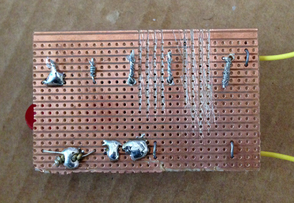
However, you should try using a matrix board instead where each hole is separate.
Step 4: Testing
Further testing was done with pulse width modulation (PWM) waves inputs:
Discussions
Become a Hackaday.io Member
Create an account to leave a comment. Already have an account? Log In.