-
How to Send sensor data to cloud using NodMcu8266 | IoT Tutorial
06/17/2020 at 15:23 • 0 commentsWe are planning to use the NodMcu8266 to automatically log temperature and humidity measurements within the cloud, and show these measurements inside an online dashboard for this we use the DHT11 sensor for Measure temperature and humidity Data in our Environment. We will complete this project by dividing it into several parts.
Part-1:
Required Component :
4.DHT11
5.Breadboard Power Supply Module
Software Required:
The latest version of the Arduino IDE, which you can get from:
http://www.arduino.cc/en/Main/SoftwareFollow this link to How to Complet Software Setup Installing the Arduino IDE for the ESP8266 | IoT Tutorial
This book will help you to gain more knowledge of the Internet of Things with ESP8266
Part-2:
After Complet your hardware Collection and Software installation now we have to need waring with sensor and esp8266
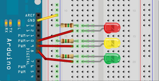
Circuit Diagram sensor Data cloud NodMcu8266:
shows how to connect a DHT 11 sensor to NodMcu8266.
![DHT sensor with nosemcu8266]()
Part-3
Now we went to test sensor work properly or not so we have to need a test for sensor
Testing the sensor:
Now we will simply print the value of the temperature inside the Serial monitor of the Arduino IDE. If it has not been done yet
,
![install the DHT sensor library using the Arduino IDE library manager.]()
install the DHT sensor library using the Arduino IDE library manager.
This is the complete code for this part:
// Libraries
#include "DHT.h"

// Pin
#define DHTPIN D5

// Use DHT11 sensor
#define DHTTYPE DHT11

// Initialize DHT sensor
DHT dht(DHTPIN, DHTTYPE, 15);

void setup() {

  // Start Serial
  Serial.begin(115200);

  // Init DHT
  dht.begin();
}

void loop() {

  // Reading temperature and humidity
  float h = dht.readHumidity();
  // Read temperature as Celsius
  float t = dht.readTemperature();

  // Display data
  Serial.print("Humidity: ");
  Serial.print(h);
  Serial.print(" %\t");
  Serial.print("Temperature: ");
  Serial.print(t);
  Serial.println(" *C ");

   // Wait a few seconds between measurements.
  delay(2000);

}
if you see like this interface then test successfully done
![DHt test output]()
Code Overview Part-3 Code:
It starts by including the required libraries:
#include "ESP8266WiFi.h"
#include "DHT.h"
To install those libraries, simply look for them inside the Arduino IDE library manager. Next, we need to set the pin that the DHT sensor is connected to:
#define DHTPIN D5
#define DHTTYPE DHT11
After that, we declare an instance of the DHT sensor:
DHT dht(DHTPIN, DHTTYPE, 15);We also define two variables that will hold the measurements of the sensor
float temperature;
float humidity;
In the setup() function of the sketch, we initialize the sensor:
dht.begin();in the loop() function, we make the measurements from the sensor:
humidity = dht.readHumidity();
temperature = dht.readTemperature();
Finally Display data on your serial monitor :
Serial.print("Humidity: ");
Serial.print(h);
Serial.print(" %\t");
Serial.print("Temperature: ");
Serial.print(t);
Serial.println(" *C ");
Part-4
We are now going to see how to Send the temperature and humidity measurements in the cloud. We will use the Dweet.io cloud service here, which is very convenient for sending data online:
Sensor data send to Dweet.io:
Code:
// Libraries
#include <ESP8266WiFi.h>
#include "DHT.h"

// WiFi parameters
const char* ssid = "Mechatronics";
const char* password = "Pa$$word";

// Pin
#define DHTPIN D5

// Use DHT11 sensor
#define DHTTYPE DHT11

// Initialize DHT sensor
DHT dht(DHTPIN, DHTTYPE, 15);

// Host
const char* host = "dweet.io";

void setup() {

  // Start Serial
  Serial.begin(115200);
  delay(10);

  // Init DHT
  dht.begin();

  // We start by connecting to a WiFi network
  Serial.println();
  Serial.println();
  Serial.print("Connecting to ");
  Serial.println(ssid);
  WiFi.begin(ssid, password);
  while (WiFi.status() != WL_CONNECTED) {
    delay(500);
    Serial.print(".");
  }

  Serial.println("");
  Serial.println("WiFi connected");
  Serial.println("IP address: ");
  Serial.println(WiFi.localIP());
}

void loop()...
Read more -
Simple SD Card/Read Write– Arduino Workshop
06/15/2020 at 13:54 • 1 commentIn this project, we will connect up an SD Card to an Arduino and by using the SD.h library to access the card, we will create a new file on the card, write some text to that file, print out the contents of that file, then delete the file. This will teach you the basic concepts of accessing an SD card and reading and writing files to it. You will need an SD Card and some way of connecting it to an Arduino. The easiest way is to get an SD/MMC Card Breakout Board from various electronics hobbyist suppliers.Required Component SD Card Arduino:
1.Arduino2. Resistors
3. SD Card & Breakout
4. connecting wire
5. Breadboard
Never connect the Arduino’s output pins directly to the SD Card without first dropping the voltage from them from 5V down to 3.3V or you will damage the SD Card
This book will help you to gain more knowledge about Arduino
Beginning ArduinoCircuit diagram SD Card Arduino
![Simple SD Card Read Write]()
![]() Digital pin 12 on the Arduino goes straight into pin 7 (DO) on the SD Card. Digital pins 13, 11, and 10 go via the resistors to drop the logic levels to 3.3V. The remaining connections to the SD card supply 3.3V to power the SD card via pin 4 and ground pins 3 and 6. Refer to the datasheet for your particular SD Card breakout board in case the pin outs differ from the circuit board above
Digital pin 12 on the Arduino goes straight into pin 7 (DO) on the SD Card. Digital pins 13, 11, and 10 go via the resistors to drop the logic levels to 3.3V. The remaining connections to the SD card supply 3.3V to power the SD card via pin 4 and ground pins 3 and 6. Refer to the datasheet for your particular SD Card breakout board in case the pin outs differ from the circuit board above
Code SD Card Arduino:
#include <SD.h>
File File1;
void setup()
{
Serial.begin(9600);
while (!Serial) { } // wait for serial port to connect.
// Needed for Leonardo only
Serial.println("Initializing the SD Card...");
if (!SD.begin()) {
Serial.println("Initialization Failed!");
return;
}
Serial.println("Initialization Complete.\n");
Serial.println("Looking for file 'testfile.txt'...\n");
if (SD.exists("testfile.txt")) {
Serial.println("testfile.txt already exists.\n");
}
else {
Serial.println("testfile.txt doesn't exist.");
Serial.println("Creating file testfile.txt...\n");
}
File1 = SD.open("testfile.txt", FILE_WRITE);
File1.close();
Serial.println("Writing text to file.....");
String dataString;
File1 = SD.open("testfile.txt", FILE_WRITE);
if (File1) {
for (int i=1; i<11; i++) {
dataString = "Test Line ";
dataString += i;
File1.println(dataString);
}
Serial.println("Text written to file.....\n");
}
File1.close();
Serial.println("Reading contents of textfile.txt...");
File1 = SD.open("testfile.txt");
if (File1) {
while (File1.available()) {
Serial.write(File1.read());
}
File1.close();
}
// if the file isn't open, pop up an error:
else {
Serial.println("error opening testfile.txt");
}
// delete the file:
Serial.println("\nDeleting testfile.txt...\n");
SD.remove("testfile.txt");
if (SD.exists("testfile.txt")){
Serial.println("testfile.txt still exists.");
}
else {
Serial.println("testfile.txt has been deleted.");
}
}
void loop()
{
//
Nothing to see here
}
Make sure that your SD card has been freshly formatted in the FAT or FAT32 format. On a Mac, ensure the partition scheme is set to “Master Boot Record.” Run the program and open the serial monitor. The program will now attempt to write a file to the SD card, write some text to that file, read back the contents of the file and then finally delete the file. This will all be displayed on the serial monitor window. If everything goes well, you will get a readout like this: Initializing the SD Card... Initialization Complete. Looking for file 'testfile.txt'... testfile.txt doesn't exist. Creating file testfile.txt... Writing text to file..... Text written to file..... Reading contents of textfile.txt... Test Line 1 Test Line 2 Test Line 3 Test Line 4 Test Line 5 Test Line 6 Test Line 7 Test Line 8 Test Line 9 Test Line 10 Deleting testfile.txt... testfile.txt has been deleted. Make sure that the card is either SD or SDHC format and that it is formatted with “Master Boot Record” or MBR partitions.All Arduino tutorial available Click here
ALL ARDUINO TUTORIAL
-
Serial Temperature Sensor– Arduino Workshop
06/15/2020 at 13:53 • 0 commentsThis project we know about Serial Temperature Sensor Arduino uses the LM35 analog temperature sensor. This sensor is part of the LM135 range of sensors from National Semiconductors. It has a range from −40°C to +100°C The circuit and code is designed for an LM35 sensor, but you can just as easily substitute an LM135 or LM235 if you wish. You will need to adjust your code accordingly to the relevant sensor. You can substitute a standard rotary potentiometer of a similar value for the 5K ohm trim pot (potentiometer). A trim pot, or trimmer potentiometer, is simply a small potentiometer designed to adjust, or trim, part of a circuit and then, once calibrated, be left alone. Any value trimmer or potentiometer with a value between 5K ohm and 10K ohm will doRequired Component
1.Arduino2. Resistors
3. LM35 Temperature Sensor
4. 5K ohm Trim Pot
5. connecting wire
6. Breadboard
7. 6×2 LCD Display Module
This book will help you to gain more knowledge about Arduino
Beginning ArduinoCircuit diagram Serial Temperature Sensor Arduino:
![Serial Temperature Sensor]() If you have the flat side of the LM35 temperature sensor facing you, the left-hand leg is the adjustment pin that goes to the center pin of the pot, the middle leg is the positive supply pin, and the right-hand leg is the ground pint. The center pin goes to analog pin 0 on the Arduino
If you have the flat side of the LM35 temperature sensor facing you, the left-hand leg is the adjustment pin that goes to the center pin of the pot, the middle leg is the positive supply pin, and the right-hand leg is the ground pint. The center pin goes to analog pin 0 on the Arduino
Code Serial Temperature Sensor Arduino:
#define sensorPin 0
float Celsius, Fahrenheit, Kelvin;
int sensorValue;
void setup() {
Serial.begin(9600);
Serial.println("Initialising.....");
}
void loop() {
GetTemp();
Serial.print("Celsius: ");
Serial.println(Celsius);
Serial.print("Fahrenheit: ");
Serial.println(Fahrenheit);
Serial.println();
delay(2000);
}
void GetTemp()
{
sensorValue = analogRead(sensorPin); // read the
sensor
Kelvin = (((float(sensorValue) / 1023) * 5) * 100); // convert to
Kelvin
Celsius = Kelvin - 273.15; // convert to
Celsius
Fahrenheit = (Celsius * 1.8) +32; // convert to
Fahrenheit
}
Enter the code and upload it to your Arduino. Once the code is running, open the serial monitor and make sure your baud rate is set to 9600. You will see the temperature displayed in both Fahrenheit and Celsius. The temperature may look incorrect to you. This is where the trimmer comes in; you must first calibrate your sensor. For proper calibration, you should be using a mixture of ice and water that has had time to stabilize at the temperature at which the ice melts. Place chopped or crushed ice in a Styrofoam cup (to limit outside influences) and either let it thaw until partially melted (in a fridge), or add some clean (ideally, distilled) water. The mixture should be at least 50 percent ice. Stir to mix well, and wait at least several minutes to make sure the water has had a chance to cool to the just freezing point. Then put the sensor (protected by a thin plastic bag with as little air as possible) in the water-ice slurry and wait until the reading stops changing. Then adjust the trimmer for a reading of 0°C. Now turn your trimmer or pot until the reading in the serial monitor shows the correct temperature. Your sensor is now calibrated. If you are using heat shrink tubing for the purpose of waterproofing the sensor, you should use a dual wall or filled-core heat type of heat-shrink tubing. You can remove the trimmer part of the circuit and it will run just fine. However, the temperature will be a close approximation, within 1°C. How the sensor works is not important (and is in fact pretty complicated) so I will simply look at how the code works for this projectAll Arduino tutorial available Click here
ALL ARDUINO TUTORIAL
-
Touch Screen Keypad– Arduino Workshop
06/15/2020 at 13:53 • 0 commentsIn this project, we know about Touch Screen Keypad using ArduinoRequired Component
1.Arduino2. Resistors
3. Nintendo DS touch screen
4. Touch screen breakout
5. connecting wire
6. Breadboard
7. 6×2 LCD Display Module
This book will help you to gain more knowledge about Arduino
Beginning ArduinoCircuit diagram Touch Screen Keypad Arduino
![Touch Screen Keypad]()
![lcd connection]()
![]() The other difference is that you will create and print out a keypad to place underneath the touch screen. The standard DS touch screen is 70mm × 55mm (2.75” × 2.16”) so you will need to create a template of this size using an art or word-processing package, and then place a set of evenly spaced keys on the rectangle so it resembles a phone keypad. Figure 12-3 shows the keypad I created. Feel free to use it.
The other difference is that you will create and print out a keypad to place underneath the touch screen. The standard DS touch screen is 70mm × 55mm (2.75” × 2.16”) so you will need to create a template of this size using an art or word-processing package, and then place a set of evenly spaced keys on the rectangle so it resembles a phone keypad. Figure 12-3 shows the keypad I created. Feel free to use it.
Code Touch Screen Keypad– Arduino:
#include <LiquidCrystal.h>
LiquidCrystal lcd(2, 3, 4, 5, 6, 7); // create an lcd object and
assign the pins
// Power connections
#define Left 8 // Left (X1) to digital pin 8
#define Bottom 9 // Bottom (Y2) to digital pin
9
#define Right 10 // Right (X2) to digital pin
10
#define Top 11 // Top (Y1) to digital pin 11
// Analog connections
#define topInput 0 // Top (Y1) to analog pin 0
#define rightInput 1 // Right (X2) to analog pin 1
int coordX = 0, coordY = 0;
char buffer[16];
void setup()
{
lcd.begin(16, 2); // Set the display to 16
columns and 2 rows
lcd.clear();
}
void loop()
{
if (touch())
{
if ((coordX>110 && coordX<300) && (coordY>170 && coordY<360))
{lcd.print("3");}
if ((coordX>110 && coordX<300) && (coordY>410 && coordY<610))
{lcd.print("2");}
if ((coordX>110 && coordX<300) && (coordY>640 && coordY<860))
{lcd.print("1");}
if ((coordX>330 && coordX<470) && (coordY>170 && coordY<360))
{lcd.print("6");}
if ((coordX>330 && coordX<470) && (coordY>410 && coordY<610))
{lcd.print("5");}
if ((coordX>330 && coordX<470) && (coordY>640 && coordY<860))
{lcd.print("4");}
if ((coordX>490 && coordX<710) && (coordY>170 && coordY<360))
{lcd.print("9");}
if ((coordX>490 && coordX<710) && (coordY>410 && coordY<610))
{lcd.print("8");}
if ((coordX>490 && coordX<710) && (coordY>640 && coordY<860))
{lcd.print("7");}
if ((coordX>760 && coordX<940) && (coordY>170 && coordY<360))
{scrollLCD();}
if ((coordX>760 && coordX<940) && (coordY>410 && coordY<610))
{lcd.print("0");}
if ((coordX>760 && coordX<940) && (coordY>640 && coordY<860))
{lcd.clear();}
delay(250);
}
}
// return TRUE if touched, and set coordinates to touchX and
touchY
boolean touch()
{
boolean touch = false;
// get horizontal co-ordinates
pinMode(Top, INPUT); // Top and Bottom to high
impedance
pinMode(Bottom, INPUT);
pinMode(Left, OUTPUT);
digitalWrite(Left, LOW); // Set Left to low
pinMode(Right, OUTPUT); // Set right to +5v
digitalWrite(Right, HIGH);
delay(3);
coordX = analogRead(topInput);
// get vertical co-ordinates
pinMode(Right, INPUT); // left and right to high
impedance
pinMode(Left, INPUT);
pinMode(Bottom, OUTPUT); // set Bottom to Gnd
digitalWrite(Bottom, LOW);
pinMode(Top, OUTPUT); // set Top to +5v
digitalWrite(Top, HIGH);
delay(3);
coordY = analogRead(rightInput);
// if co-ordinates read are less
than 1000 and greater than 24
// then the screen has been touched
if(coordX < 1000 && coordX > 24 && coordY < 1000 && coordY >
24) {touch = true;}
return touch;
}
void scrollLCD() {
for (int scrollNum=0; scrollNum<16; scrollNum++) {
lcd.scrollDisplayLeft();
delay(100);
}
lcd.clear();
}
Enter the code and upload it to your Arduino. Slide the keypad template underneath the keypad with the ribbon cable at the bottom right (next to the E). You can now press the keys on the touch screen and what you press is displayed on the LCD. When you press the C (for Clear) button, the display will clear. When you press the E (for Enter) key, the numbers displayed will scroll to the left until they disappear.All Arduino tutorial available Click here
ALL ARDUINO TUTORIAL
-
Basic Touch Screen– Arduino Workshop
06/15/2020 at 13:52 • 0 commentsFor this project, We know about Basic Touch Screen Arduino and you will need a Nintendo DS touch screen as well as a breakout module. The latter is essential as the output from the touch screen is a very thin and fragile ribbon connector, and it will be impossible to interface to the Arduino without additional components. Required Component 1.Arduino2. Resistors
3. Nintendo DS touch screen
4. Touch screen breakout
5. connecting wire
6. Breadboard
This book will help you to gain more knowledge about Arduino
Beginning ArduinoCircuit diagram Basic Touch Screen Arduino:
![Basic Touch Screen]() The breakout unit has pins marked as X1, Y2, X2, and Y1. Connect the pins as described in Table. You will need a connection from the IOREF pin (or 5V pin if you have an older Arduino without an IOREF pin) to the breadboard and then suitably high-value resistors (around 50K) between the X2 and Y1 pins and the IOREF line on the breadboard.
The breakout unit has pins marked as X1, Y2, X2, and Y1. Connect the pins as described in Table. You will need a connection from the IOREF pin (or 5V pin if you have an older Arduino without an IOREF pin) to the breadboard and then suitably high-value resistors (around 50K) between the X2 and Y1 pins and the IOREF line on the breadboard.
![Connect the pins as described in Table]() You will need to solder some header pins to the breakout unit. The pins are soldered such that The SparkFun logo is facing upward. The screen is connected to the breakout unit via the small connector. Pull back the tab and push the tiny ribbon cable into the connector, then push the tab closed to lock it in place. The screen goes with the ribbon connector at the top right when connecting. From now on, be very careful with the unit: it is very fragile and easily broken! I broke three screens and two breakouts in testing. If you can find a way of fixing the breadboard, breakout, and touch screen in place to prevent it from moving, you should do so.
You will need to solder some header pins to the breakout unit. The pins are soldered such that The SparkFun logo is facing upward. The screen is connected to the breakout unit via the small connector. Pull back the tab and push the tiny ribbon cable into the connector, then push the tab closed to lock it in place. The screen goes with the ribbon connector at the top right when connecting. From now on, be very careful with the unit: it is very fragile and easily broken! I broke three screens and two breakouts in testing. If you can find a way of fixing the breadboard, breakout, and touch screen in place to prevent it from moving, you should do so.
Code Basic Touch Screen Arduino:
// Power connections
#define Left 8 // Left (X1) to digital pin 8
#define Bottom 9 // Bottom (Y2) to digital pin 9
#define Right 10 // Right (X2) to digital pin 10
#define Top 11 // Top (Y1) to digital pin 11
// Analog connections
#define topInput 0 // Top (Y1) to analog pin 0
#define rightInput 1 // Right (X2) to analog pin 1
int coordX = 0, coordY = 0;
void setup()
{
Serial.begin(38400);
}
void loop()
{
if (touch()) // If screen touched, print coordinates
{
Serial.print(coordX);
Serial.print(" ");
Serial.println(coordY);
delay(250);
}
}
// return TRUE if touched, and set coordinates to touchX and
touchY
boolean touch()
{
boolean touch = false;
// get horizontal co-ordinates
pinMode(Top, INPUT); // Top and Bottom to high impedance
pinMode(Bottom, INPUT);
pinMode(Left, OUTPUT);
digitalWrite(Left, LOW); // Set Left to low
pinMode(Right, OUTPUT); // Set right to +5v
digitalWrite(Right, HIGH);
delay(3);
coordX = analogRead(topInput);
// get vertical co-ordinates
pinMode(Right, INPUT); // left and right to high impedance
pinMode(Left, INPUT);
pinMode(Bottom, OUTPUT); // set Bottom to Gnd
digitalWrite(Bottom, LOW);
pinMode(Top, OUTPUT); // set Top to +5v
digitalWrite(Top, HIGH);
delay(3);
coordY = analogRead(rightInput);
// if co-ordinates read are less than
1000 and greater than 24
// then the screen has been touched
if(coordX < 1000 && coordX > 24 && coordY < 1000 && coordY >
24) {touch = true;}
return touch;
}
Enter the code and upload it to your Arduino. Once it is running, open up the serial monitor, and then touch the touch screen. Whenever the screen is touched, the coordinates of your finger will be displayed on the serial monitor. The coordinates are x across the horizontal plane going from left to right and y across the vertical plane going from top to bottomAll Arduino tutorial available Click here
ALL ARDUINO TUTORIAL
-
Digital Pressure Sensor– Arduino Workshop
06/15/2020 at 13:51 • 0 commentsIn this project, we are going to Digital Pressure Sensor– Arduino and learn how to use an MPL3115A2 pressure sensor, the MPL3115A2 digital pressure sensor from Freescale. This is a great sensor that is easily interfaced with an Arduino and provides accurate pressure and temperature readings. The device needs to be connected to the Arduino’s I2C (inter-integrated circuit or I-Squared-C, also known as a two-wire interface (TWI)) bus for data to be exchanged. I2C is a new concept for you, and although this chapter will not cover it in great detail, you will learn the basic concepts of the I2C and how to use it to get data from the MPL3115A2 sensor. Digital pressure sensors are ideal for making your own weather station.Required Component :
1.Arduino Uno Or Maga2. MPL3115A2 Pressure Sensor
3. Connecting wire
4. Breadboard
This book will help you to gain more knowledge about Arduino
Beginning ArduinoCircuit diagram Digital Pressure Sensor Arduino :
![Digital Pressure Sensor]() I have used an Arduino Mega instead of an Uno for these projects as it has extra pins free for adding additional devices, if you wish. If you do use an Arduino Uno for your project, the SDA and SCLsignals are on the analog-in 4 and analog-in 5 pins, respectively. This is different from the Arduino Mega, which uses pins 20 and 21 instead.
This project simply requires the Uno, the MPL3115A2 on a breakout board, and a few wires. Connect the GND pin on the sensor to the GND pin on the Arduino. Connect the VCC pin on the sensor to the 3.3V pin on the Uno. Then connect the SDA (serial data) and SCL(serial clock) pins on the Uno to the corresponding SDA and SCLpins on the sensor.
Be aware that the wire library turns on the internal pull-ups to 5V and the MPL3115A2 requires a maximum voltage of 3.6 volts on the SDA and SCLpins. The Sparkfun breakout board has pull-up resistors to bring that down to a safe 3.3V. If the MPL3115A2 is the only device on the I2C bus, the pull-ups to 3.3V on the breakout board will keep the signal levels within a safe range.
If you add any other devices to the I2C bus that operate at 5V and have on-board pull-ups like the MPL3115A2 breakout board does, you could easily damage the MPL3115A2 and any other 3.3V-only I2C devices on the bus. Therefore, do not add any other I2C devices to this project without also providing some protection.
One way to avoid these problems is to clamp the SCLand SDA lines using low-capacitance 3.6-
volt Zener diodes to the ground (3.6V because of the nonlinear knee on the Zener curve). Another way is
to use LEDs with a 3.1 – 3.4-volt forward voltage to clamp the lines. (Most blue and white LEDs
have a forward voltage in that range.)
I have used an Arduino Mega instead of an Uno for these projects as it has extra pins free for adding additional devices, if you wish. If you do use an Arduino Uno for your project, the SDA and SCLsignals are on the analog-in 4 and analog-in 5 pins, respectively. This is different from the Arduino Mega, which uses pins 20 and 21 instead.
This project simply requires the Uno, the MPL3115A2 on a breakout board, and a few wires. Connect the GND pin on the sensor to the GND pin on the Arduino. Connect the VCC pin on the sensor to the 3.3V pin on the Uno. Then connect the SDA (serial data) and SCL(serial clock) pins on the Uno to the corresponding SDA and SCLpins on the sensor.
Be aware that the wire library turns on the internal pull-ups to 5V and the MPL3115A2 requires a maximum voltage of 3.6 volts on the SDA and SCLpins. The Sparkfun breakout board has pull-up resistors to bring that down to a safe 3.3V. If the MPL3115A2 is the only device on the I2C bus, the pull-ups to 3.3V on the breakout board will keep the signal levels within a safe range.
If you add any other devices to the I2C bus that operate at 5V and have on-board pull-ups like the MPL3115A2 breakout board does, you could easily damage the MPL3115A2 and any other 3.3V-only I2C devices on the bus. Therefore, do not add any other I2C devices to this project without also providing some protection.
One way to avoid these problems is to clamp the SCLand SDA lines using low-capacitance 3.6-
volt Zener diodes to the ground (3.6V because of the nonlinear knee on the Zener curve). Another way is
to use LEDs with a 3.1 – 3.4-volt forward voltage to clamp the lines. (Most blue and white LEDs
have a forward voltage in that range.)
Code Digital Pressure Sensor Arduino :
#include <Wire.h> // so we can use I2C communication
#define MYALTITUDE 262 //define altitude at your location to
calculate mean sea level pressure in meters
// Register addresses
const int SENSORADDRESS = 0x60; // MPL3115A1 address from the
datasheet
#define SENSOR_CONTROL_REG_1 0x26
#define SENSOR_DR_STATUS 0x00 // Address of DataReady status
register
#define SENSOR_OUT_P_MSB 0x01 // Starting address of Pressure
Data registers
float baroAltitudeCorrectionFactor = 1/(pow(1-
MYALTITUDE/44330.77,5.255877));
byte I2Cdata[5] = {0,0,0,0,0}; //buffer for sensor data
void setup(){
Wire.begin(); // join i2c bus
Serial.begin(9600); // start serial for output at 9600 baud
Serial.println("Setup");
I2C_Write(SENSOR_CONTROL_REG_1, 0b00000000); // put in standby
mode
// these upper bits of the control register
// can only be changed while in standby
I2C_Write(SENSOR_CONTROL_REG_1, 0b00111000); // set oversampling
to 128
Serial.println("Done.");
}
void loop(){
float temperature, pressure, baroPressure;
Read_Sensor_Data();
temperature = Calc_Temperature();
pressure = Calc_Pressure();
baroPressure = pressure * baroAltitudeCorrectionFactor;
Serial.print("Absolute pressure: ");
Serial.print(pressure); // in Pascal
Serial.print(" Pa, Barometer: ");
Serial.print(baroPressure);...
Read more -
Basic Stepper Control – Arduino Workshop
06/15/2020 at 13:51 • 0 commentsIn this very simple project, you will connect up a stepper motor and then get the Arduino to control it in different directions and at different speeds for a set number of steps. Basic Stepper Control - Arduino Workshop simple project to show you how to control the stepper, make it move a set distance, and change its speed and direction. Stepper motors are different than standard motors in that their rotation is divided into a series of steps. By controlling the timing and number of steps issued to the motor, you can control the speed of the motor and how far it turns fairly precisely. Stepper motors come in different shapes and sizes and have four, five, six, or eight wires. Stepper motors have many uses; they are used in flatbed scanners to position the scanning head and in inkjet printers to control the location of the print head and paperRequired Component :
1.Arduino2. Resistors
3. Stepper Motor
4. SN754410 Motor Driver IC
5 .0.1uF capacitors
6. Connecting wire
7. Breadboard
This book will help you to gain more knowledge about Arduino
Beginning ArduinoCircuit diagram Basic Stepper Control Arduino:
![Basic Stepper Control]() Make sure the Arduino and the L293 are connected to an external DC power supply so as not to overload the Arduino. The Arduino does not need to be connected to an external supply, the SN754410 does. It is best to run the connection to the external supply positive lead directly to the breadboard and pin 8 of the SN754410 and connected to the ground from the Arduino at the breadboard.
By doing this rather than hooking pin 8 of the SN754410 to the Vin pin from the Arduino’s shield connector, high currents won’t be routed through the Arduino. The capacitors are optional and help to smooth out the current and prevent interference with the Arduino. These go between the +5v and ground and the motor power supply and ground.
You can also use low-value electrolytic capacitors, but make sure you connect them correctly (+ to supply, - to the ground) as they are polarized and can be damaged or explode if hooked up backward! I found that without them the circuit did not work.
You may also require a current-limiting resistor between the power supply and the power rail supplying the SN754410 chip. Use an appropriate power supply that is within the range of both voltage and current for your motor. Also, ensure that the power rating of any current-limiting resistors you use is above the current required by the motor or the resistor will heat up and burn out.
Note that the motor drive voltage will also be lower than the input voltage due to the internal voltage drops in the driver.
Digital pins 4, 5, 6, and 7 on the Arduino go to the input 1, 2, 3, and 4 pins on the motor driver. Output pins 1 and 2 of the motor driver go across coil 1 of the motor and output pins 3 and 4 to coil 2. You will need to check the datasheet of your specific motor to see which colored wires go to coil 1 and which go to coil 2. A unipolar motor will also have a 5th and/or a 6th wire that goes to ground
The 5v pin on the Arduino goes to pin 16 (VSS) of the motor driver pin. the two chip inhibit pins (1 and 9) are also tied to the 3.3v line to make them go HIGH. making sure neither half of the driver chip is inhibited.
The Vin (Voltage in) pin on the Arduino goes to pin 8 of the driver IC (VC). Pins 4, 5, 12, and 13 all go to ground. Once you are happy that everything is connected up as it should be, enter the code below
Make sure the Arduino and the L293 are connected to an external DC power supply so as not to overload the Arduino. The Arduino does not need to be connected to an external supply, the SN754410 does. It is best to run the connection to the external supply positive lead directly to the breadboard and pin 8 of the SN754410 and connected to the ground from the Arduino at the breadboard.
By doing this rather than hooking pin 8 of the SN754410 to the Vin pin from the Arduino’s shield connector, high currents won’t be routed through the Arduino. The capacitors are optional and help to smooth out the current and prevent interference with the Arduino. These go between the +5v and ground and the motor power supply and ground.
You can also use low-value electrolytic capacitors, but make sure you connect them correctly (+ to supply, - to the ground) as they are polarized and can be damaged or explode if hooked up backward! I found that without them the circuit did not work.
You may also require a current-limiting resistor between the power supply and the power rail supplying the SN754410 chip. Use an appropriate power supply that is within the range of both voltage and current for your motor. Also, ensure that the power rating of any current-limiting resistors you use is above the current required by the motor or the resistor will heat up and burn out.
Note that the motor drive voltage will also be lower than the input voltage due to the internal voltage drops in the driver.
Digital pins 4, 5, 6, and 7 on the Arduino go to the input 1, 2, 3, and 4 pins on the motor driver. Output pins 1 and 2 of the motor driver go across coil 1 of the motor and output pins 3 and 4 to coil 2. You will need to check the datasheet of your specific motor to see which colored wires go to coil 1 and which go to coil 2. A unipolar motor will also have a 5th and/or a 6th wire that goes to ground
The 5v pin on the Arduino goes to pin 16 (VSS) of the motor driver pin. the two chip inhibit pins (1 and 9) are also tied to the 3.3v line to make them go HIGH. making sure neither half of the driver chip is inhibited.
The Vin (Voltage in) pin on the Arduino goes to pin 8 of the driver IC (VC). Pins 4, 5, 12, and 13 all go to ground. Once you are happy that everything is connected up as it should be, enter the code below
Code Basic Stepper Control Arduino :
#include <Stepper.h>
// steps value is 360 / degree angle of motor
#define STEPS 200
// create a stepper object on pins 4, 5, 6 and 7
Stepper stepper(STEPS, 4, 5, 6, 7);
void setup()
{
}
void loop()
{
stepper.setSpeed(60);
stepper.step(200);
delay(100);
stepper.setSpeed(20);
stepper.step(-50);
delay(100);
}
Make sure that your Arduino is powered by an external DC power supply before running the code. When the sketch runs, you will see the stepper motor rotate a full rotation, stop... Read more -
Dual Servo Control - Arduino Workshop
06/15/2020 at 13:50 • 0 commentsThis project, we will create Dual Servo Control using Arduino, this time will control two servos using commands from the serial monitor.Required Component :
1.Arduino2. Resistors
3. Standard RC Servo
4.Potentiometer
5. connecting wire
6. Breadboard
This book will help you to gain more knowledge about Arduino
Beginning ArduinoCircuit diagram Dual Servo Control Arduino :
You will need to obtain a standard RC servo; any of the small or mid-sized servos will do. The servo must be powered by its own power supply. Do not power it from the Arduino’s 5V supply as this will cause both noise and excessive heat, potentially disrupting the program or worse, damaging the Arduino. Use an external 5V supply or a battery pack. Make sure the ground of both the Arduino and the power supply is connected. Also, add a resistor in series between the Arduino’s output and the control input of the servo to limit current if the Arduino is on when the servo’s supply is off. A 220-ohm resistor will do here. Also, you’ll need a potentiometer; pretty much any value rotary potentiometer will do. I used a 4.7K ohm one for testing. Note that you may also wish to connect your Arduino to an external DC power supply![Dual Servo Control]() The servo has three wires coming from it. One will be red and will go to +5V. One will be black or brown and will go to the ground. The third will be white, yellow, or orange and will be connected to digital pin 5 via a 220-ohm resistor.
Basically, you remove the potentiometer from the Servo Control- Arduino Workshop project and wire a second servo up to digital pin 6 via a 220-ohm resistor. Once everything is connected as it should be, enter the code below.
The servo has three wires coming from it. One will be red and will go to +5V. One will be black or brown and will go to the ground. The third will be white, yellow, or orange and will be connected to digital pin 5 via a 220-ohm resistor.
Basically, you remove the potentiometer from the Servo Control- Arduino Workshop project and wire a second servo up to digital pin 6 via a 220-ohm resistor. Once everything is connected as it should be, enter the code below.
Code Dual Servo Control Arduino:
#include <Servo.h>
char buffer[11];
Servo servo1; // Create a servo object
Servo servo2; // Create a second servo object
void setup()
{
servo1.attach(5); // Attaches the servo on pin 5 to the
servo1 object
servo2.attach(6); // Attaches the servo on pin 6 to the
servo2 object
Serial.begin(9600);
while(Serial.available())
Serial.read();
servo1.write(90); // Put servo1 at home position
servo2.write(90); // Put servo2 at home postion
Serial.println("STARTING...");
}
void loop()
{
if (Serial.available() > 0) { // Check if data has been
entered
int index=0;
delay(100); // Let the buffer fill up
int numChar = Serial.available(); // Find the string
length
if (numChar>10) {
numChar=10;
}
while (numChar--) {
// Fill the buffer with the string
buffer[index++] = Serial.read();
}
buffer[index]='\0';
splitString(buffer); // Run splitString function
}
}
void splitString(char* data) {
Serial.print("Data entered: ");
Serial.println(data);
char* parameter;
parameter = strtok (data, " ,"); //String to token
while (parameter != NULL) { // If we haven't reached the end
of the string...
setServo(parameter); // ...run the setServo function
parameter = strtok (NULL, " ,");
}
while(Serial.available())
Serial.read();
}
void setServo(char* data) {
if ((data[0] == 'L') || (data[0] == 'l')) {
int firstVal = strtol(data+1, NULL, 10); // String to
long integer
firstVal = constrain(firstVal,0,180); // Constrain
values
servo1.write(firstVal);
Serial.print("Servo1 is set to: ");
Serial.println(firstVal);
}
if ((data[0] == 'R') || (data[0] == 'r')) {
int secondVal = strtol(data+1, NULL, 10); // String
to long integer
secondVal = constrain(secondVal,0,255); //
Constrain the values
servo2.write(secondVal);
Serial.print("Servo2 is set to: ");
Serial.println(secondVal);
}
}
To run the code, open up the serial monitor window. The Arduino will reset, and the servos will move to their central locations. You can now use the serial monitor to send commands to the Arduino. The left servo is controlled by sending a Land than a number between 0 and 180 for the angle. The right servo is controlled by sending an R and the number. You can send individual commands to each servo or send both commands at the same time by separating the commands with... Read more -
Servo Control- Arduino Workshop
06/15/2020 at 13:50 • 0 commentsIn this very simple project, you will control a single servo using Arduino and a potentiometer. A servo is a motor with a feedback system that helps to control the position of the motor. Servos typically rotate through 180 degrees, although you can also buy continuous rotation servos or even modify a standard one for continuous rotation. If you have ever owned a radio-controlled (RC) airplane, you have come across servos; they are used to control the flight surfaces. RC cars use them for the steering mechanism, and RC boats use them to control the rudder. Likewise, they are often used as the moving joints in small robot arms and for controlling movement in animatronics. Servos are really easy to control thanks to the servo library that comes with the Arduino IDE.Required Component :
1.Arduino2. Resistors
3. Standard RC Servo
4.Potentiometer
5. connecting wire
6. Breadboard
This book will help you to gain more knowledge about Arduino
Beginning ArduinoCircuit diagram Servo Control Arduino :
You will need to obtain a standard RC servo; any of the small or mid-sized servos will do. The servo must be powered by its own power supply. Do not power it from the Arduino’s 5V supply as this will cause both noise and excessive heat, potentially disrupting the program or worse, damaging the Arduino. Use an external 5V supply or a battery pack. Make sure the ground of both the Arduino and the power supply is connected. Also, add a resistor in series between the Arduino’s output and the control input of the servo to limit current if the Arduino is on when the servo’s supply is off. A 220-ohm resistor will do here. Also, you’ll need a potentiometer; pretty much any value rotary potentiometer will do. I used a 4.7K ohm one for testing. Note that you may also wish to connect your Arduino to an external DC power supply![Servo Control]() The servo has three wires coming from it. One will be red and will go to +5V. One will be black or brown and will go to the ground. The third will be white, yellow, or orange and will be connected to digital pin 5 via a 220-ohm resistor. The rotary potentiometer has the outer pins connected to +5V and ground and the middle pin to analog pin 0. Once everything is connected as it should be, enter the code below.
The servo has three wires coming from it. One will be red and will go to +5V. One will be black or brown and will go to the ground. The third will be white, yellow, or orange and will be connected to digital pin 5 via a 220-ohm resistor. The rotary potentiometer has the outer pins connected to +5V and ground and the middle pin to analog pin 0. Once everything is connected as it should be, enter the code below.
Code Servo Control Arduino :
#include <Servo.h>
Servo servo1; // Create a servo object
void setup()
{
servo1.attach(5); // Attaches the servo on Pin 5 to the
servo object
}
void loop()
{
int angle = analogRead(0); // Read the pot value
angle=map(angle, 0, 1023, 0, 180); // Map the values from 0
to 180 degrees
servo1.write(angle); // Write the angle to the servo
delay(15); // Delay of 15ms to allow servo to reach position
}
All Arduino tutorial available Click here
ALL ARDUINO TUTORIAL
-
LCD Temperature Display- Arduino Workshop
06/15/2020 at 13:49 • 0 commentsThis project will be a simple demonstration of LCD Temperature Display using an LCD to present useful information to the user, in this case, the temperature readout from an analog temperature sensor. We will also add a button to enable the temperature to be displayed in either centigrade or Fahrenheit, whichever you prefer. Also, the maximum and minimum temperatures will be displayed in the second row.Required Component :
1.Arduino2. Resistors
3. 6×2 LCD Display Module
4.Potentiometer
5. connecting wire
6. Breadboard
8. LM35DTAnalog Temp Sensor LM35
Circuit diagram LCD Temperature Display:
I have used an LM35DT temperature sensor, which has a range from 0ºC to 100ºC. You can, of course, use any analog temperature sensor you wish. The LM35 ranges from −55ºC to +150ºC. You will need to adjust your code accordingly![LCD Temperature Display]()
Code LCD Temperature Display:
LiquidCrystal lcd(12, 11, 5, 4, 3, 2); // create an lcd
object and assign the pins
int maxC=0, minC=100, maxF=0, minF=212;
int scale = 1;
int buttonPin=8;
void setup() {
lcd.begin(16, 2); // Set the display
to 16 columns and 2 rows
analogReference(INTERNAL);
// analogReference(INTERNAL1V1); If you have an Arduino Mega
pinMode(buttonPin, INPUT);
lcd.clear();
}
void loop() {
lcd.setCursor(0,0); // set cursor to
home position
int sensor = analogRead(0); // read the temp
from sensor
int buttonState = digitalRead(buttonPin); // check for button
press
switch (buttonState) { // change scale
state if pressed
case HIGH:
scale=-scale; // invert scale
lcd.clear();
}
switch (scale) { // decide if C or F
scale
case 1:
celsius(sensor);
break;
case -1:
fahrenheit(sensor);
}
delay(250);
}
void celsius(int sensor) {
lcd.setCursor(0,0);
int temp = sensor * 0.1074188; // convert to C
lcd.print(temp);
lcd.write(B11011111); // degree symbol
lcd.print("C ");
if (temp>maxC) {maxC=temp;}
if (temp<minC) {minC=temp;}
lcd.setCursor(0,1);
lcd.print("H=");
lcd.print(maxC);
lcd.write(B11011111);
lcd.print("C L=");
lcd.print(minC);
lcd.write(B11011111);
lcd.print("C ");
}
void fahrenheit(int sensor) {
lcd.setCursor(0,0);
float temp = ((sensor * 0.1074188) * 1.8)+32; // convert to F
lcd.print(int(temp));
lcd.write(B11011111); // print degree
symbol
lcd.print("F ");
if (temp>maxF) {maxF=temp;}
if (temp<minF) {minF=temp;}
lcd.setCursor(0,1);
lcd.print("H=");
lcd.print(maxF);
lcd.write(B11011111);
lcd.print("F L=");
lcd.print(minF);
lcd.write(B11011111);
lcd.print("F ");
}
When you run the code, the current temperature will be displayed on the LCD on the top row. The bottom row will display the maximum and minimum temperatures recorded since the Arduino was turned on or the program reset. By pressing the button you can change the temperature scale between Celsius and FahrenheitAll Arduino tutorial available Click here
ALL ARDUINO TUTORIAL
-
Basic LCD Control- Arduino Workshop
06/15/2020 at 13:48 • 0 commentswe will create a demonstration project Arduino Basic LCD Control that will show off most of the functions available in the LiquidCrystal.h library. We will be using a backlit 16x2 LCD Display. You will need to obtain an LCD display that uses the HD44780 driver. There are many available, and they come in all kinds of colors. As an amateur astronomer, I particularly like the red-on-black displays as they preserve your night vision. These have red text on a black background. You can, of course, choose any available color text and background you wish. Your display must have a backlight and be able to display sixteen columns and two rows of characters. These are often referred to as 16x2 LCD displaysRequired Component :
1.Arduino2. Resistors
3. 6x2 LCD Display Module
4.Potentiometer
5. connecting wire
6. Breadboard
This book will help you to gain more knowledge about Arduino
Beginning ArduinoCircuit diagram Basic LCD Control:
![lcd connection]() Data pins 0 to 3 are not used, as we are going to use what is known as 4-bit mode, The contract adjustment pin on the LCD must be connected via a current-limiting resistor to adjust the contrast to the desired level. A value of around 10KΩ should suffice. If you find it difficult to get the right value, then connect a potentiometer with a value between about 4KΩ to 10KΩ with the left leg to +5V, the right leg to the ground, and the center leg to the contrast adjustment pin (pin 3 on my LCD).
This way, you can use the knob to adjust the contrast until you can see the display clearly. The backlight on the LCD I used required 4.2V, so I added the appropriate current-limiting resistor between +5V and the LED power supply pin (pin 15 in my LCD). You could, of course, connect the LED power pin to a PWM pin (via a current-limiting resistor) on the Arduino and use a PWM output to control the brightness of the backlight.
For simplicity’s sake, we will not use that method in this project. Once you are happy that your circuit matches mine with the correct pins going between the Arduino, +5V, and ground (according to the LCDs datasheet), then you can enter the code
Data pins 0 to 3 are not used, as we are going to use what is known as 4-bit mode, The contract adjustment pin on the LCD must be connected via a current-limiting resistor to adjust the contrast to the desired level. A value of around 10KΩ should suffice. If you find it difficult to get the right value, then connect a potentiometer with a value between about 4KΩ to 10KΩ with the left leg to +5V, the right leg to the ground, and the center leg to the contrast adjustment pin (pin 3 on my LCD).
This way, you can use the knob to adjust the contrast until you can see the display clearly. The backlight on the LCD I used required 4.2V, so I added the appropriate current-limiting resistor between +5V and the LED power supply pin (pin 15 in my LCD). You could, of course, connect the LED power pin to a PWM pin (via a current-limiting resistor) on the Arduino and use a PWM output to control the brightness of the backlight.
For simplicity’s sake, we will not use that method in this project. Once you are happy that your circuit matches mine with the correct pins going between the Arduino, +5V, and ground (according to the LCDs datasheet), then you can enter the code
![Basic LCD Control]()
Code Basic LCD Control
#include <LiquidCrystal.h>
// initialize the library with the numbers of the interface pins
LiquidCrystal lcd(12, 11, 5, 4, 3, 2); // create an lcd object and
assign the pins
void setup() {
lcd.begin(16, 2); // Set the display to 16
columns and 2 rows
}
void loop() {
// run the 7 demo routines
basicPrintDemo();
displayOnOffDemo();
setCursorDemo();
scrollLeftDemo();
scrollRightDemo();
cursorDemo();
createGlyphDemo();
}
void basicPrintDemo() {
lcd.clear(); // Clear the display
lcd.print("Basic Print"); // print some text
delay(2000);
}
void displayOnOffDemo() {
lcd.clear(); // Clear the display
lcd.print("Display On/Off"); // print some text
for(int x=0; x < 3; x++) { // loop 3 times
lcd.noDisplay(); // turn display off
delay(1000);
lcd.display(); // turn it back on again
delay(1000);
}
}
void setCursorDemo() {
lcd.clear(); // Clear the display
lcd.print("SetCursor Demo"); // print some text
delay(1000);
lcd.clear(); // Clear the display
lcd.setCursor(5,0); // cursor at column 5 row 0
lcd.print("5,0");
delay(2000);
lcd.setCursor(10,1); // cursor at column 10 row
1
lcd.print("10,1");
delay(2000);
lcd.setCursor(3,1); // cursor at column 3 row 1
lcd.print("3,1");
delay(2000);
}
void scrollLeftDemo() {
lcd.clear(); // Clear the display
lcd.print("Scroll Left Demo");
delay(1000);
lcd.clear(); // Clear the display
lcd.setCursor(7,0);
lcd.print("Beginning");
lcd.setCursor(9,1);
lcd.print("Arduino");
delay(1000);
for(int x=0; x<16; x++) {
lcd.scrollDisplayLeft(); // scroll display left 16
times
delay(250);
}
}
void scrollRightDemo() {
lcd.clear(); // Clear the display
lcd.print("Scroll Right");
lcd.setCursor(0,1);
lcd.print("Demo");
delay(1000);
lcd.clear(); // Clear the display
lcd.print("Beginning");
lcd.setCursor(0,1);
lcd.print("Arduino");
delay(1000);
for(int x=0; x<16; x++) {
lcd.scrollDisplayRight(); // scroll display...
Read more -
Arduino Workshop-Shift Register 8-Bit Binary Counter
06/15/2020 at 13:47 • 0 commentsIn this project, we are going to use additional ICs in the form Shift Register 8-Bit Binary Counter, to enable us to drive LEDs to display a binary counter. In this project, we will drive eight LEDs independently using just three output pins from the Arduino.Required Component :
1.Arduino2. Resistors
3. 5mm LED
4.0.1uF capacitors
5.74HC595 Shift Register IC
6. connecting wire
7. Breadboard
This book will help you to gain more knowledge about Arduino
Beginning ArduinoCircuit diagram Shift Register 8-Bit Binary Counter:
Examine the diagram carefully. Connect the 5V to the top rail of your breadboard and the ground to the bottom. The chip has a small dimple on one end; this dimple goes to the left. Pin 1 is below the dimple, pin 8 at bottom right, pin 9 at top right, and pin 16 at the top left. You now need wires to go from the 5V supply to pins 10 and 16, as well as wires from the ground to pins 8 and 13. A wire goes from digital pin 8 to pin 12 on the IC. Another one goes from digital pin 12 to pin 11 on the IC, and finally, one from digital pin 11 to pin 14 on the IC. The 8 LED’s have a 560Ω resistor between the cathode and ground. The anode of LED 1 goes to pin 15. The anode of LEDs 2 to 8 goes to pins 1 to 7 on the IC. You will need a bypass capacitor (otherwise known as a decoupling capacitor) to go between the power supply pin and the ground. Make sure its voltage rating is higher than the supply voltage being used. The leads should be kept short, with the capacitor as close to the chip as possible. The purpose of this capacitor is to reduce the effect of electrical noise on the circuit. Once you have connected everything up as in Figure , check that your wiring is correct and the IC and LEDs are the right way around. Then enter the code. [caption id="attachment_478" align="alignnone" width="300"]![Shift Register 8-Bit Binary Counter]() Shift Register 8-Bit Binary Counter[/caption]
Shift Register 8-Bit Binary Counter[/caption]
Code Shift Register 8-Bit Binary Counter :
int latchPin = 8; //Pin connected to Pin 12 of 74HC595 (Latch)
int clockPin = 12; //Pin connected to Pin 11 of 74HC595 (Clock)
int dataPin = 11; //Pin connected to Pin 14 of 74HC595 (Data)
void setup() {
//set pins to output
pinMode(latchPin, OUTPUT);
pinMode(clockPin, OUTPUT);
pinMode(dataPin, OUTPUT);
}
void loop() {
//count from 0 to 255
for (int i = 0; i < 256; i++) {
shiftDataOut(i);
//set latchPin low then high to send data out
digitalWrite(latchPin, LOW);
digitalWrite(latchPin, HIGH);
delay(1000);
}
}
void shiftDataOut(byte dataOut) {
// Shift out 8 bits LSB first, clocking each with a rising
edge of the clock line
boolean pinState;
for (int i=0; i<=7; i++) { // for each bit in
dataOut send out a bit
digitalWrite(clockPin, LOW); //set clockPin to
LOW prior to sending bit
// if the value of DataOut and (logical AND) a
bitmask
// are true, set pinState to 1 (HIGH)
if ( dataOut & (1<<i) ) {
pinState = HIGH;
}
else {
pinState = LOW;
}
//sets dataPin to HIGH or LOW depending on pinState
digitalWrite(dataPin, pinState); //send bit out
before rising edge of clock
digitalWrite(clockPin, HIGH);
}
digitalWrite(clockPin, LOW); //stop shifting out data
}
All Arduino tutorial available Click here
ALL ARDUINO TUTORIAL
-
Arduino Workshop-Using an L293D Motor Driver IC
06/15/2020 at 13:47 • 0 commentsIn this project, we are going to use a very popular motor driver IC called an L293D. The advantage of using this chip is that we can control two motors at the same time, as well as control their direction. The chip can also be used to control a stepper motorRequired Component of L293D Motor Driver IC:
1.Arduino2.Potentiometer
3.DC Motor
4. L293DMotor Driver IC
5.Slide Switch
6.0.1uF capacitors
7. Resistors
8. connecting wire
9. Breadboard
10.LiPo Battery
This book will help you to gain more knowledge about Arduino
Beginning ArduinoCircuit diagram:
First, make sure your Arduino is powered off by unplugging it from the USB cable. Now take the required parts and connect them up as in Figure Using an L293D Motor Driver IC. Again, check the circuit thoroughly before powering it up. The L293D can get hot when in use, and therefore a heatsink is recommended. Glue the heatsink to the top of the chip using special thermal epoxy glue, thermally conductive double-sided tape, or use a clip-on style heat sink. The larger the heatsink, the better. Be warned that the temperature can get hot enough to melt the plastic on a breadboard or any wires touching it. Do not touch the heatsink as you may burn yourself and ensure you do not leave the circuit powered up and unattended in case it overheats. [caption id="attachment_475" align="alignnone" width="300"]![Using an L293D Motor Driver IC]() Using an L293D Motor Driver IC[/caption]
Using an L293D Motor Driver IC[/caption]
Code L293D Motor Driver IC:
#define switchPin 2 // switch input
#define motorPin1 3 // L293D Input 1
#define motorPin2 4 // L293D Input 2
#define speedPin 9 // L293D enable pin 1
#define potPin 0 // Potentiometer on analog Pin 0
int Mspeed = 0; // a variable to hold the current speed value
void setup() {
//set switch pin as INPUT
pinMode(switchPin, INPUT);
// set remaining pins as outputs
pinMode(motorPin1, OUTPUT);
pinMode(motorPin2, OUTPUT);
pinMode(speedPin, OUTPUT);
}
void loop() {
Mspeed = analogRead(potPin)/4; // read the speed value from the
potentiometer
analogWrite (speedPin, Mspeed); // write speed to Enable 1 pin
if (digitalRead(switchPin)) { // If the switch is HIGH, rotate
motor clockwise
digitalWrite(motorPin1, LOW); // set Input 1 of the L293D low
digitalWrite(motorPin2, HIGH); // set Input 2 of the L293D high
}
else { // if the switch is LOW, rotate motor anti-clockwise
digitalWrite(motorPin1, HIGH); // set Input 1 of the L293D low
digitalWrite(motorPin2, LOW); // set Input 2 of the L293D high
}
}
Once the code has finished uploading, set the potentiometer at its midpoint, and plug in the external power supply. The motor will now rotate and you can adjust its speed by turning the potentiometer. To change the direction of the motor, first set the speed to minimum, then flick the switch. The motor will now rotate in the opposite direction. Again be careful of that chip, as it will get very hot once powered up.All Arduino tutorial available Click here
ALL ARDUINO TUTORIAL
-
Arduino Workshop-Simple Motor Control
06/15/2020 at 13:46 • 0 commentsThis tutorial we are going to Arduino Simple Motor Control, in one direction, using a power transistor, diode, and external power supply to power the motor and a potentiometer to control the speed. Any suitable NPN power transistor designed for high current loads can replace the TIP120 transistor. However, I would highly recommend you use a power Darlington-type transistor. Make sure you choose a transistor that can handle the voltage and current your motor will draw. It may be necessary to fit a heat sink to the transistor if it is pulling more than about an amp. The external power supply can be a set of batteries or a “wall wart”-style external DC power supply. The power source must have enough voltage and current to drive the motor. The voltage must not exceed that required by the motor. For my testing purposes, I used a DC power supply that provided 5V at 500mA. This was enough for the 5V DC motor I was using. If you use a power supply with voltage higher than the motor can take, you may damage it permanentlyRequired Component of Arduino Simple Motor Control :
1.Arduino2.Potentiometer
3.DC Motor
4. 1N4001 Diode with TIP120 Transistor
5. Resistors
6. connecting wire
7. Breadboard
8.LiPo Battery
This book will help you to gain more knowledge about Arduino
Beginning ArduinoCircuit diagram of Arduino Simple Motor Control:
First, make sure your Arduino is powered off by unplugging it from the USB cable. Now, take the required parts and connect them up It is essential for this project that you check and double-check all of your connections are as they should be before supplying power to the circuit, as failure to do so may result in damage to your components or even your Arduino. The diode, in particular, is essential to protect the Arduino from back EMF, which we will explain later.![First, make sure your Arduino is powered off by unplugging it from the USB cable. Now, take the required parts and connect them up as in Figure 5-1. It is essential for this project that you check and double check all of your connections are as they should be before supplying power to the circuit, as failure to do so may result in damage to your components or even your Arduino. The diode, in particular, is essential to protect the Arduino from back EMF, which we will explain later.]()
Code Arduino of Simple Motor Control:
int potPin = 0; // Analog in 0 connected to the
potentiometer
int transistorPin = 9; // PWM Pin 9 connected to the base of
the transistor
int potValue = 0; // value returned from the potentiometer
void setup() {
// set the transistor pin as output:
pinMode(transistorPin, OUTPUT);
}
void loop() {
// read the potentiometer, convert it to 0 - 255:
potValue = analogRead(potPin) / 4;
// use that to control the transistor:
analogWrite(transistorPin, potValue);
}
Before uploading your code, disconnect the external power supply to the motor and ensure the potentiometer is turned fully counterclockwise. Now upload the code to the Arduino. Once the code is uploaded, connect the external power supply. You can now turn the potentiometer to control the speed of the motorAll Arduino tutorial available Click here ALL ARDUINO TUTORIAL
-
Arduino Workshop-Light Sensor
06/15/2020 at 13:45 • 0 commentsIn this project, we will use an LDR to detect light and a piezo sounder to give audible feedback of the amount of the light detected, a light-dependent resistor, or LDR. As the name implies, the device is a resistor that depends on light. In a dark environment, the resistor will have very high resistance. As photons (light) land on the detector, the resistance will decrease. The more light there is, the lower the resistance will be. By reading the value from the sensor, we can detect if it is light, dark, or anywhere in-betweenRequired Component : 1.Arduino
2. Piezo Sounder
3. Resistors
4. connecting wire
5. Breadboard
This book will help you to gain more knowledge about ArduinoBeginning ArduinoCircuit diagram Arduino Light Sensor : First, make sure your Arduino is powered off by unplugging it from the USB cable. Then, connect up your parts so you have the circuit. Check all of your connections before reconnecting the power to the Arduino. The LDR can be inserted any way around; it does not have polarity. I found a 10kΩ resistor worked well with my LDR. You may need to try different resistor settings until you find one suitable for the LDR you have. A value between 1kΩ and 10kΩ should do the trick. Having a selection of different common resistor values in your component box will always come in handy. [caption id="attachment_448" align="alignnone" width="300"]
![Light Sensor]() Light Sensor[/caption]
Code Arduino Light Sensor :
Light Sensor[/caption]
Code Arduino Light Sensor :
int piezoPin = 8; // Piezo on Pin 8
int ldrPin = 0; // LDR on Analog Pin 0
int ldrValue = 0; // Value read from the LDR
void setup() {
// nothing to do here
}
void loop() {
ldrValue = analogRead(ldrPin); // read the value from the
LDR
tone(piezoPin,1000); // play a 1000Hz tone from the piezo
delay(25); // wait a bit
noTone(piezoPin); // stop the tone
delay(ldrValue); // wait the amount of milliseconds in
ldrValue
}
When you upload this code to the Arduino, the Arduino will start to make short beeps. The gap between the beeps will be long if the LDR is in the shade and will be short when bright light is shone on it. This will give a Geiger counter-type effect, but with our detector detecting photon particles instead of ionizing radiation. You may find it more practical to solder a set of long wires to the LDR to allow you to keep your breadboard and Arduino on the table but move your LDR around to point it in dark and light areas. ALL ARDUINO TUTORIAL -
Arduino Workshop-Piezo Knock Sensor
06/15/2020 at 13:45 • 0 commentsToday in this project we are going to create a Piezo Knock Sensor, A piezo disc works when an electric field (voltage) is applied across ceramic material in the disc, causing it to change shape and therefore make a sound (a click). The disc also works in reverse in that when the disc is knocked or squeezed, the force on the material causes an electric charge (voltage) to be generated. We can read that current using the Arduino and we are going to do that now by making a knock sensor. Required Component : 1.Arduino2. Piezoelectric Sensor
3. 5mm LED
4. Resistors
5. connecting wire
6. Breadboard
This book will help you to gain more knowledge about ArduinoBeginning ArduinoCircuit diagram Arduino Piezo Knock Sensor : First, make sure your Arduino is powered off by unplugging it from the USB cable. Then connect up your parts so that you have the circuit in Piezo Knock Sensor. A piezo disc works better for this project than a piezo sounder. The resistor on the piezo is there to discharge any piezo capacitance built up in the piezo while it is being used. [caption id="attachment_442" align="alignnone" width="300"]
![Piezo Knock Sensor]() Piezo Knock Sensor[/caption]
Code Arduino Piezo Knock Sensor :
Piezo Knock Sensor[/caption]
Code Arduino Piezo Knock Sensor :
int ledPin = 9; // LED on Digital Pin 9
int piezoPin = 5; // Piezo on Analog Pin 5
int threshold = 120; // The sensor value to reach before
activation
int sensorValue = 0; // A variable to store the value read from
the sensor
float ledValue = 0; // The brightness of the LED
void setup() {
pinMode(ledPin, OUTPUT); // Set the ledPin to an OUTPUT
// Flash the LED twice to show the program has started
digitalWrite(ledPin, HIGH); delay(150); digitalWrite(ledPin,
LOW); delay(150);
digitalWrite(ledPin, HIGH); delay(150); digitalWrite(ledPin,
LOW); delay(150);
}
void loop() {
sensorValue = analogRead(piezoPin); // Read the value from
the sensor
if (sensorValue >= threshold) { // If knock detected set
brightness to max
ledValue = 255;
}
analogWrite(ledPin, int(ledValue) ); // Write brightness
value to LED
ledValue = ledValue - 0.05; // Dim the LED slowly
if (ledValue <= 0) { ledValue = 0;} // Make sure value does
not go below zero
}
After you have uploaded your code, the LED will flash quickly twice to show you that the program has started. You can now knock the sensor or squeeze it between your fingers. Every time the Arduino detects a knock or squeeze, the LED will light up and then gently fade back down to off. The threshold value in the code was set for the piezo disc I used when building the project. You may need to set this to a higher or lower value depending on the type and size of the piezo you have used for your project. Lower is more sensitive and higher is less ALL ARDUINO TUTORIAL -
Arduino Workshop-Piezo Sounder Alarm
06/14/2020 at 16:26 • 0 commentsToday in this project we are going to create a wailing alarm sound, By connecting a piezo sounder to a digital output pin this is very, this is a very simple project I will show you in this project step by step Required Component : 1.Arduino2. Piezo Sounder
his book will help you to gain more knowledge about ArduinoBeginning ArduinoCircuit diagram Arduino Piezo Sounder Alarm : First, make sure your Arduino is powered off by unplugging it from the USB cable Then Connect up your Arduino Piezo Sounder Alarm and connect your Arduino back to the USB cable and power it up [caption id="attachment_439" align="alignnone" width="300"]
![Piezo Sounder Alarm]() Piezo Sounder Alarm[/caption]
Code :
Piezo Sounder Alarm[/caption]
Code :
float sinVal;
int toneVal;
void setup() {
pinMode(8, OUTPUT);
}
void loop() {
for (int x=0; x<180; x++) {
// convert degrees to radians then obtain sin value
sinVal = (sin(x*(3.1412/180)));
// generate a frequency from the sin value
toneVal = 2000+(int(sinVal*1000));
tone(8, toneVal);
delay(2);
}
}
Once you have uploaded the code, there will be a slight delay, and then your piezo will start to emit sounds. If everything is working as planned, you will hear a rising and falling siren-type alarm, similar to a car alarm. ALL ARDUINO TUTORIAL -
Arduino Workshop-RGB Mood Lamp
06/14/2020 at 16:25 • 0 commentsIn the last project, we saw that we could adjust the brightness of an LED using the PWM capabilities of the Atmega chip. We will now take advantage of this capability by using a red, green, and blue LED and by mixing the colors to create any color we wish. Required Component for RGB Mood Lamp 1.Arduino2. RGB led 5mm
3. Resistors
4. connecting wire
5. Breadboard
This book will help you to gain more knowledge about ArduinoBeginning ArduinoCircuit diagram Arduino RGB Mood Lamp : Connect up your three LEDs as in Figure RGB Mood Lamp [caption id="attachment_434" align="alignnone" width="300"]
![RGB Mood Lamp]() RGB Mood Lamp[/caption]
Code Arduino RGB Mood Lamp :
RGB Mood Lamp[/caption]
Code Arduino RGB Mood Lamp :
float RGB1[3];
float RGB2[3];
float INC[3];
int red, green, blue;
int RedPin = 11;
int GreenPin = 10;
int BluePin = 9;
void setup()
{
Serial.begin(9600);
randomSeed(analogRead(0));
RGB1[0] = 0;
RGB1[1] = 0;
RGB1[2] = 0;
RGB2[0] = random(256);
RGB2[1] = random(256);
RGB2[2] = random(256);
}
void loop()
{
randomSeed(analogRead(0));
for (int x=0; x<3; x++) {
INC[x] = (RGB1[x] - RGB2[x]) / 256; }
for (int x=0; x<256; x++) {
red = int(RGB1[0]);
green = int(RGB1[1]);
blue = int(RGB1[2]);
analogWrite (RedPin, red);
analogWrite (GreenPin, green);
analogWrite (BluePin, blue);
delay(100);
RGB1[0] -= INC[0];
RGB1[1] -= INC[1];
RGB1[2] -= INC[2];
}
for (int x=0; x<3; x++) {
RGB2[x] = random(556)-300;
RGB2[x] = constrain(RGB2[x], 0, 255);
delay(1000);
}
}
When you run this, you will see the colors slowly change. You’ve just made your own mood lamp.Code Antonyms Arduino RGB Mood Lamp :We have used an RGB LED. This is a single 5mm LED, with four legs (some have more). One leg is either a common anode (positive) or common cathode (negative) and the other three go to the opposite terminal of the red, green, and blue LEDs inside the lamp.An RGB value of 255, 0, 0 would give us pure red. A value of 0, 255, 0 would give pure green, and 0, 0, 255, pure blue. By mixing these, we can get any color we like. This is the additive color model.![Color Mixer]() In the code, we start off by declaring some floating point arrays and also some integer variables that will store our RGB values as well as an increment value. float RGB1[3]; float RGB2[3]; float INC[3]; int red, green, blue; In the setup function, we have randomSeed(analogRead(0));The randomSeed command is used for creating random (actually pseudo-random) numbers. Computer chips are not able to produce truly random numbers, so they use a mathematical function that generates a very long sequence of pseudo-random values before repeating. By setting a “seed,” you can tell the computer wherein the sequence to start returning random numbers. In this case, the value we give to the randomSeed is a value read from analog pin 0.As we don’t have anything connected to analog pin 0, all we will read is a random number created by analog noise. Once we have set a “seed” for our random number, we can create one using the random() function. We then have two sets of RGB values stored in a three-element array. RGB1 is the RGB value we want the lamp to start with (in this case, all zeros or off). RGB1[0] = 0; RGB1[1] = 0; RGB1[2] = 0; The RGB2 array is a set of random RGB values that we want the lamp to transition toRGB2[0] = random(256); RGB2[1] = random(256); RGB2[2] = random(256); In this case, we have set the RGB values to a random number set by random(256), which will give us a number between 0 and 255 inclusive (as the number will always range from zero upward). If you pass a single number to the random() function, then it will return a value between 0 and 1 less than the number; random(1000) will return a number between 0 and 999.If you supply two numbers as parameters, then it will return a random number between the lower number inclusive and the maximum number minus 1 (−1). For example, random(10,100) will return a random number between 10 and 99. In the main program loop, we first take a look at the start...Read more
In the code, we start off by declaring some floating point arrays and also some integer variables that will store our RGB values as well as an increment value. float RGB1[3]; float RGB2[3]; float INC[3]; int red, green, blue; In the setup function, we have randomSeed(analogRead(0));The randomSeed command is used for creating random (actually pseudo-random) numbers. Computer chips are not able to produce truly random numbers, so they use a mathematical function that generates a very long sequence of pseudo-random values before repeating. By setting a “seed,” you can tell the computer wherein the sequence to start returning random numbers. In this case, the value we give to the randomSeed is a value read from analog pin 0.As we don’t have anything connected to analog pin 0, all we will read is a random number created by analog noise. Once we have set a “seed” for our random number, we can create one using the random() function. We then have two sets of RGB values stored in a three-element array. RGB1 is the RGB value we want the lamp to start with (in this case, all zeros or off). RGB1[0] = 0; RGB1[1] = 0; RGB1[2] = 0; The RGB2 array is a set of random RGB values that we want the lamp to transition toRGB2[0] = random(256); RGB2[1] = random(256); RGB2[2] = random(256); In this case, we have set the RGB values to a random number set by random(256), which will give us a number between 0 and 255 inclusive (as the number will always range from zero upward). If you pass a single number to the random() function, then it will return a value between 0 and 1 less than the number; random(1000) will return a number between 0 and 999.If you supply two numbers as parameters, then it will return a random number between the lower number inclusive and the maximum number minus 1 (−1). For example, random(10,100) will return a random number between 10 and 99. In the main program loop, we first take a look at the start...Read more -
Arduino Workshop-Pulsating Lamp
06/14/2020 at 16:24 • 0 commentsToday I show you how to control your led brightness its very easy work I show you step by step and it also calls Pulsating Lamp
Required Component for Arduino LED Chase Effect
1.Arduino
2. 5mm LED
3. Resistors
This book will help you to gain more knowledge about ArduinoCircuit diagram Pulsating Lamp:
![]() Pulsating Lamp[/caption]
Pulsating Lamp[/caption]The circuit for this project is simply a green LED connecting, via a current-limiting resistor, between
ground and Digital Pin 11Code Pulsating Lamp:
int ledPin = 11;
float sinVal;
int ledVal;
void setup() {
pinMode(ledPin, OUTPUT);
}
void loop() {
for (int x=0; x<180; x++) {
// convert degrees to radians then obtain sin value
sinVal = (sin(x*(3.1412/180)));
ledVal = int(sinVal*255);
analogWrite(ledPin, ledVal);
delay(25);
}
}
Verify and upload. You will now see your LED pulsate on and off steadily. Instead of a simple
on/off state, we are now adjusting its brightness. Let’s find out how this worksCode Antonyms :The code for this project is very simple but requires some explanation. We first set up the variables for the LED Pin, afloat (floating-point data type) for a sine wave value, and ledVal which will hold the integer value to send out to Pin 11. The concept here is that we are creating a sine wave and having the brightness of the LED follows the path of that wave. This is what makes the light pulsate instead of fading up to full brightness and back down again.We use the sin() function, which is a mathematical function for the sine of an angle. We need to give the function the angle, expressed in radians. We have a for loop that goes from 0 to 179; we don’t want to go past halfway as this will take us into negative values, and the brightness value we need to put out to Pin 11 needs to be from 0 to 255 only. The sin() function requires the angle to be in radians, and not degrees, so the equation of x* (3.1412/180) will convert the degree angle into radians.We then transfer the result to ledVal, multiplying it by 255 to give us our value. The result from the sin() function will be a number between −1 and 1, so we need to multiply that by 255 to give us our maximum brightness. We “cast” the floating-point value of signal into an integer by the use of int() in the statement level = int(sinVal*255); Then we send that value out to digital pin 11 using the statement analogWrite(ledPin, ledVal); Casting means to convert a value in one data type to a different data type (in this case, floating-point to integer, by throwing away the portion after the decimal point).But, how can we send an analog value to a digital pin? Well, if we take a look at our Arduino and look at the digital pins, you can see that 6 of those pins (3, 5, 6, 9, 10 & 11) have PWM written next to them. Those pins differ from the remaining digital pins in that they are able to send out a PWM signal, which stands for pulse width modulation. PWM is a technique for getting analog results from digital means. On these pins, the Arduino sends out a rectangle wave by switching the pin on and off very fast. The pattern of on/offs can simulate a varying voltage between 0 and 5V. It does this by changing the amount of time that the output remains high (on) versus off (low).The duration of the on-time is known as the pulse width. For example, if you were to send the value 0 out to pin 11 using analogWrite(), the ON period would be zero, or it would have a 0% duty cycle. If you were to send a value of 64 (25% of the maximum of 255), the pin would be ON for 25% of the time and OFF for 75% of the time.The value of 191 would have a duty cycle of 75% and a value of 255 would have a duty cycle of 100%. The pulses run at a speed of approximately 500Hz, or 2 milliseconds each. So, from this, we can see in our sketch that the LED is being turned on and off very fast. If the duty cycle were 50% (a value of 127), then the LED would pulse on...Read more -
Arduino Workshop-Interactive LED Chase Effect
06/14/2020 at 16:23 • 0 commentsArduino Workshop-LED Chase Effect We are going to add a potentiometer to this circuit which will allow you to change the speed of the lights while the code is running
Required Component
1.Arduino
2. 5mm LED3. 4.7KΩ Rotary PotentiometerThis book will help you to gain more knowledge about ArduinoALL ARDUINO TUTORIALCircuit diagram Arduino Interactive LED Chase Effect
First, make sure your Arduino is powered off by unplugging it from the USB cable. Now add a potentiometer to the circuit so it is connected as in Figure Interactive LED Chase Effect with the left leg going to the 5V on the Arduino, the middle leg going to Analog Pin 2, and the right leg going to ground. [caption id="attachment_412" align="alignnone" width="300"]![Interactive LED Chase Effect]() Figure: Interactive LED Chase Effect[/caption]
How Work potentiometer:
The potentiometer is simply a fixed resistor with an adjustable wiper that can be used to divide the total resistance into two parts that add up to the total (fixed) value.
[caption id="attachment_414" align="alignnone" width="200"]
Figure: Interactive LED Chase Effect[/caption]
How Work potentiometer:
The potentiometer is simply a fixed resistor with an adjustable wiper that can be used to divide the total resistance into two parts that add up to the total (fixed) value.
[caption id="attachment_414" align="alignnone" width="200"]![potentiometer]() potentiometer[/caption]
The potentiometer has three legs. By connecting up just two legs, the potentiometer becomes a variable resistor. By connecting all three legs and applying a voltage across it, the potentiometer becomes a voltage divider. This is how we have used it in our circuit. One side is connected to the ground, the other to 5V, and the center pin to our analog pin. By adjusting the knob, a voltage between 0 and 5V will be available from the center pin; we can read the value of that voltage on Analog Pin 2 and use its value to change the delay rate of the light effect. The potentiometer can be very useful in providing a means of adjusting a value from 0 to a set
the amount, e.g., the volume of a radio or the brightness of a lamp.
potentiometer[/caption]
The potentiometer has three legs. By connecting up just two legs, the potentiometer becomes a variable resistor. By connecting all three legs and applying a voltage across it, the potentiometer becomes a voltage divider. This is how we have used it in our circuit. One side is connected to the ground, the other to 5V, and the center pin to our analog pin. By adjusting the knob, a voltage between 0 and 5V will be available from the center pin; we can read the value of that voltage on Analog Pin 2 and use its value to change the delay rate of the light effect. The potentiometer can be very useful in providing a means of adjusting a value from 0 to a set
the amount, e.g., the volume of a radio or the brightness of a lamp.
Code Arduino Interactive LED Chase Effect
byte ledPin[] = {4, 5, 6, 7, 8, 9, 10, 11, 12, 13}; // Create
array for LED pins
int ledDelay; // delay
between changes
int direction = 1;
int currentLED = 0;
unsigned long changeTime;
int potPin = 2; // select
the input pin for the potentiometer
void setup() {
for (int x=0; x<10; x++) { // set all
pins to output
pinMode(ledPin[x], OUTPUT);
}
changeTime = millis();
}
void loop() {
ledDelay = analogRead(potPin); // read the
value from the pot
if ((millis() - changeTime) > ledDelay) { // if it has
been ledDelay ms since last change
changeLED();
changeTime = millis();
}
}
void changeLED() {
for (int x=0; x<10; x++) { // turn off
all LED's
digitalWrite(ledPin[x], LOW);
}
digitalWrite(ledPin[currentLED], HIGH); // turn on the
current LED
currentLED += direction; // increment
by the direction value
// change direction
if we reach the end
if (currentLED == 9) {direction = -1;}
if (currentLED == 0) {direction = 1;}
}
This time when you verify and upload your code, you should now see the lit LED appear to bounce back and forth between each end of the string of lights as before. But, by turning the knob of the potentiometer, you will change the value of delay and speed up or slow down the effect. Let’s take a look at how this works and find out what a potentiometer is. -
Arduino Workshop-Traffic Lights
06/14/2020 at 16:20 • 0 commentsWe are now going to create a set of traffic lights based on the system that will change from green to red, via amber, and back again, after a set length of time using the four-state system
Parts Required Arduino traffic Lights
You can read this book and it will help you to learn more About Arduino Beginning Arduino
Circuit Diagram Arduino traffic Lights
![]()
Traffic LightsConnect your circuit as in Traffic Lights. This time, we have connected three LEDs with the anode of each one going to digital pins 8, 9 and 10, via a 150Ω current-limiting resistor (or whichever value you require) for each. Figure 2-6. The circuit for Project 3 We have taken a jumper wire from the ground of the Arduino to the ground rail at the top of the breadboard. A ground wire goes from the cathode leg of each LED to the common ground rail via a current-limiting resistor (this time, connected to the cathode). For this simple circuit, it doesn’t matter if the resistor is connected between the digital pin and the anode, or between the cathode and ground, as long as it is in series with the LED
Code
int ledDelay = 10000; // delay in between changes
int redPin = 10;
int yellowPin = 9;
int greenPin = 8;
void setup() {
pinMode(redPin, OUTPUT);
pinMode(yellowPin, OUTPUT);
pinMode(greenPin, OUTPUT);
}
void loop() {
digitalWrite(redPin, HIGH); // turn the red light on
delay(ledDelay); // wait 5 seconds
digitalWrite(yellowPin, HIGH); // turn on yellow
delay(2000); // wait 2 seconds
digitalWrite(greenPin, HIGH); // turn green on
digitalWrite(redPin, LOW); // turn red off
digitalWrite(yellowPin, LOW); // turn yellow off
delay(ledDelay); // wait ledDelay milliseconds
digitalWrite(yellowPin, HIGH); // turn yellow on
digitalWrite(greenPin, LOW); // turn green off
delay(2000); // wait 2 seconds
digitalWrite(yellowPin, LOW); // turn yellow off
// now our loop repeats
}
Previous tutorial
-
Arduino Workshop-LED Flashers
06/14/2020 at 16:14 • 0 commentsNow we are going to the first four projects. These projects all use LED lights in various ways. You will learn about controlling outputs from the ArduinoParts Required
You can read this book and it will help you to learn more About Arduino Beginning ArduinoCircuit Diagram LED Flashers
 First, make sure your Arduino is powered off by unplugging it from the USB cable. Next, take your breadboard, LED, resistor, and wires, and connect everything up as in Circuit Diagram,
Make sure that your LED is connected the right way. Make sure the anode (positive) leg of the LED (usually the leg with the longer lead) is connected to digital pin 7. Make sure the anode of the LED (usually the lead with the longer leg) is connected to the resistor, and the cathode (usually the short leg) to ground. LEDs only light up when the anode is at a more positive voltage than the cathode. If you connect it backward, it won’t light, but won’t damage the LED either in this circuit.
When you are sure that everything is connected up correctly, power up your Arduino and connect the USB cableCode LED Flashers
int ledPin = 7;
void setup() {
pinMode(ledPin, OUTPUT);
}
void loop() {
digitalWrite(ledPin, HIGH);
delay(1000);
digitalWrite(ledPin, LOW);
delay(1000);
}
Now press the Verify button at the top of the IDE to make sure there are no errors in your code. If this is successful, you can now click the Upload button to upload the code to your Arduino. If you have done everything correctly, you should now see the LED on the breadboard flashing on and off every second. Now let’s take a look at the code and the hardware and find out how they both work


 Digital pin 12 on the Arduino goes straight into pin 7 (DO) on the SD Card. Digital pins 13, 11, and 10 go via the resistors to drop the logic levels to 3.3V. The remaining connections to the SD card supply 3.3V to power the SD card via pin 4 and ground pins 3 and 6. Refer to the datasheet for your particular SD Card breakout board in case the pin outs differ from the circuit board above


 The other difference is that you will create and print out a keypad to place underneath the touch screen. The standard DS touch screen is 70mm × 55mm (2.75” × 2.16”) so you will need to create a template of this size using an art or word-processing package, and then place a set of evenly spaced keys on the rectangle so it resembles a phone keypad. Figure 12-3 shows the keypad I created. Feel free to use it.


 I have used an Arduino Mega instead of an Uno for these projects as it has extra pins free for adding additional devices, if you wish. If you do use an Arduino Uno for your project, the SDA and SCLsignals are on the analog-in 4 and analog-in 5 pins, respectively. This is different from the Arduino Mega, which uses pins 20 and 21 instead.
This project simply requires the Uno, the MPL3115A2 on a breakout board, and a few wires. Connect the GND pin on the sensor to the GND pin on the Arduino. Connect the VCC pin on the sensor to the 3.3V pin on the Uno. Then connect the SDA (serial data) and SCL(serial clock) pins on the Uno to the corresponding SDA and SCLpins on the sensor.
Be aware that the wire library turns on the internal pull-ups to 5V and the MPL3115A2 requires a maximum voltage of 3.6 volts on the SDA and SCLpins. The Sparkfun breakout board has pull-up resistors to bring that down to a safe 3.3V. If the MPL3115A2 is the only device on the I2C bus, the pull-ups to 3.3V on the breakout board will keep the signal levels within a safe range.
If you add any other devices to the I2C bus that operate at 5V and have on-board pull-ups like the MPL3115A2 breakout board does, you could easily damage the MPL3115A2 and any other 3.3V-only I2C devices on the bus. Therefore, do not add any other I2C devices to this project without also providing some protection.
One way to avoid these problems is to clamp the SCLand SDA lines using low-capacitance 3.6-
volt Zener diodes to the ground (3.6V because of the nonlinear knee on the Zener curve). Another way is
to use LEDs with a 3.1 – 3.4-volt forward voltage to clamp the lines. (Most blue and white LEDs
have a forward voltage in that range.)
I have used an Arduino Mega instead of an Uno for these projects as it has extra pins free for adding additional devices, if you wish. If you do use an Arduino Uno for your project, the SDA and SCLsignals are on the analog-in 4 and analog-in 5 pins, respectively. This is different from the Arduino Mega, which uses pins 20 and 21 instead.
This project simply requires the Uno, the MPL3115A2 on a breakout board, and a few wires. Connect the GND pin on the sensor to the GND pin on the Arduino. Connect the VCC pin on the sensor to the 3.3V pin on the Uno. Then connect the SDA (serial data) and SCL(serial clock) pins on the Uno to the corresponding SDA and SCLpins on the sensor.
Be aware that the wire library turns on the internal pull-ups to 5V and the MPL3115A2 requires a maximum voltage of 3.6 volts on the SDA and SCLpins. The Sparkfun breakout board has pull-up resistors to bring that down to a safe 3.3V. If the MPL3115A2 is the only device on the I2C bus, the pull-ups to 3.3V on the breakout board will keep the signal levels within a safe range.
If you add any other devices to the I2C bus that operate at 5V and have on-board pull-ups like the MPL3115A2 breakout board does, you could easily damage the MPL3115A2 and any other 3.3V-only I2C devices on the bus. Therefore, do not add any other I2C devices to this project without also providing some protection.
One way to avoid these problems is to clamp the SCLand SDA lines using low-capacitance 3.6-
volt Zener diodes to the ground (3.6V because of the nonlinear knee on the Zener curve). Another way is
to use LEDs with a 3.1 – 3.4-volt forward voltage to clamp the lines. (Most blue and white LEDs
have a forward voltage in that range.)


 Shift Register 8-Bit Binary Counter[/caption]


 Light Sensor[/caption]
Code Arduino Light Sensor :
Light Sensor[/caption]
Code Arduino Light Sensor :


 Piezo Knock Sensor[/caption]
Code Arduino Piezo Knock Sensor :
Piezo Knock Sensor[/caption]
Code Arduino Piezo Knock Sensor :


 RGB Mood Lamp[/caption]
Code Arduino RGB Mood Lamp :
RGB Mood Lamp[/caption]
Code Arduino RGB Mood Lamp :


 Pulsating Lamp[/caption]
 Figure: Interactive LED Chase Effect[/caption]
How Work potentiometer:
The potentiometer is simply a fixed resistor with an adjustable wiper that can be used to divide the total resistance into two parts that add up to the total (fixed) value.
[caption id="attachment_414" align="alignnone" width="200"]
Figure: Interactive LED Chase Effect[/caption]
How Work potentiometer:
The potentiometer is simply a fixed resistor with an adjustable wiper that can be used to divide the total resistance into two parts that add up to the total (fixed) value.
[caption id="attachment_414" align="alignnone" width="200"] potentiometer[/caption]
The potentiometer has three legs. By connecting up just two legs, the potentiometer becomes a variable resistor. By connecting all three legs and applying a voltage across it, the potentiometer becomes a voltage divider. This is how we have used it in our circuit. One side is connected to the ground, the other to 5V, and the center pin to our analog pin. By adjusting the knob, a voltage between 0 and 5V will be available from the center pin; we can read the value of that voltage on Analog Pin 2 and use its value to change the delay rate of the light effect. The potentiometer can be very useful in providing a means of adjusting a value from 0 to a set
the amount, e.g., the volume of a radio or the brightness of a lamp.
potentiometer[/caption]
The potentiometer has three legs. By connecting up just two legs, the potentiometer becomes a variable resistor. By connecting all three legs and applying a voltage across it, the potentiometer becomes a voltage divider. This is how we have used it in our circuit. One side is connected to the ground, the other to 5V, and the center pin to our analog pin. By adjusting the knob, a voltage between 0 and 5V will be available from the center pin; we can read the value of that voltage on Analog Pin 2 and use its value to change the delay rate of the light effect. The potentiometer can be very useful in providing a means of adjusting a value from 0 to a set
the amount, e.g., the volume of a radio or the brightness of a lamp.