 Eric Herbers
Overview:
Hardware tests have determined that measuring the average (after applying standard deviation) time-of-flight of approximately 500+ round-trip transmissions can produce reasonably consistent results. While this has not produced results that are accurate down to the foot, it can detect distances within 40 feet reasonably well. However, measurements are in ranges: IE 0-1, 1-4, 4-14, 14-etc. What this means is that we may know we're somewhere between 1 to 4 feet, the next step is somewhere between 4 to 14 and so on. It's not as precise as I wanted, but it is repeatable. At the speeds a 16 mHz Arduino is capable of and a 250 bps transmission rate, this is a measurement at approximately every second.
In this particular case I used a Trinket Pro 3v (12 MHz) to serve as the transponder. Its role with the examples I have provided is to configure the transceiver on the transponder end and keep the receive buffer empty. Ultimately it can be used to turn on and off the transceiver as needed, through detecting motion, to conserve power.
On the base station I used an Arduino Micro as it was readily available. It also benefits from having a 16 bit timer on Timer1 which allows for measurements up to 4 milliseconds long with 62.5 nanosecond accuracy. Ultimately this is important as you need the timer to be as accurate as possible (running at a prescaler of 1 so it cycles at the clock speed of the microcontroller), but still be able to count to a high enough number before the timer counter rolls-over. With a typical 8 bit timer, you would only be able to measure up to 16 microseconds while an average round-trip transmission takes 810 microseconds, in this case.
We can't rely on the normal means to measure time on an Arduino as they can be affected by interrupts running on the microcontroller; this has a negative effect on the consistency of the time measurements. Through the use of the 16 bit timer and being very careful about how interrupts are handled, we can achieve reasonably good measurements.
For the transceiver I used the Nordic nRF24L01+ as it is a reasonably priced transceiver that has a nice feature set. It is a 2.4 GHz transceiver, however, which is not as preferable in this application. A lower frequency transceiver may be able to reach further distances with less interference. Regardless, the main attraction to this transceiver is that it has an auto-acknowledgement function. This allows use to measure round-trip time without the microcontroller on the transponder end needing to take any immediate action. This greatly improves the reliability of the results and makes the job a little easier.
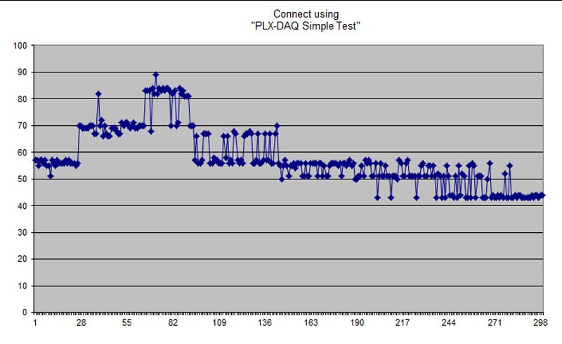
Results:
Data from the demo video.
Program Operation:
The code for the base station largely does this:
- Configure the transceiver
- Configure Timer1 to run in normal mode (to use the 16 bit counter) and at a prescaler of 1
- Send an initial packet of data to load the transmit buffer (TX FIFO)
- Set the transceiver to disable the auto-retransmit feature so we can get reliable results
- Set the transceiver to reuse the last transmitted payload so we don't have to write to the TX FIFO again
- Ping the transponder repeatedly until we achieve the desired number of samples
It then calculates the standard deviation of the raw values and only uses values that fall within the standard deviation to calculate the final average; this gets rid of values with a large margin of error which improves the consistency of the final result. At this point we use the serial connection back to the PC to relay the data so it can be reviewed and used.
Build Details:
For the base station I simply left everything on a breadboard for ease of use. In this case where we're building more of a demonstration and proof of concept, I didn't feel that building an enclosure was necessary.
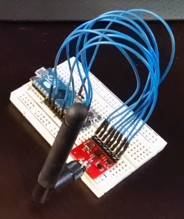
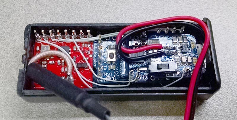
The transponder is built using a 2xAAA battery case from RadioShack. I found that this was marginally large enough and provided little room for soldering; I recommend a 2xAA case specifically for the extra width and height. Using side-cutters, the battery support ribs in the case were removed to allow room for the boards. The SMA connector was removed from the transceiver and the antenna was butchered to directly solder it to the board; I felt this would provide better reception than using the breakout board that was available with a chip antenna. The ground plane of the antenna had to be wrapped in heat-shrink to prevent it from shorting any pins.
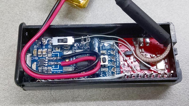
Both the Trinket Pro and Transceiver were then secured to the case using double-sided tape and, due to the space limitations, wire wrapped to make the connections between the two. Due to the height restrictions I had to directly solder the battery to the LiPo Backpack and trim down the height of the terminal posts as well as remove the plastic support ribs from them. The Trinket Pro was also modified by cutting the trace to pin A0 and jumper it to 3.3 volts; this is due to the space restrictions caused by the small case and LiPo backpack. Like I said, use a AA case! Ultimately the AAA case works and it's crazy small, but what a pain in the butt.
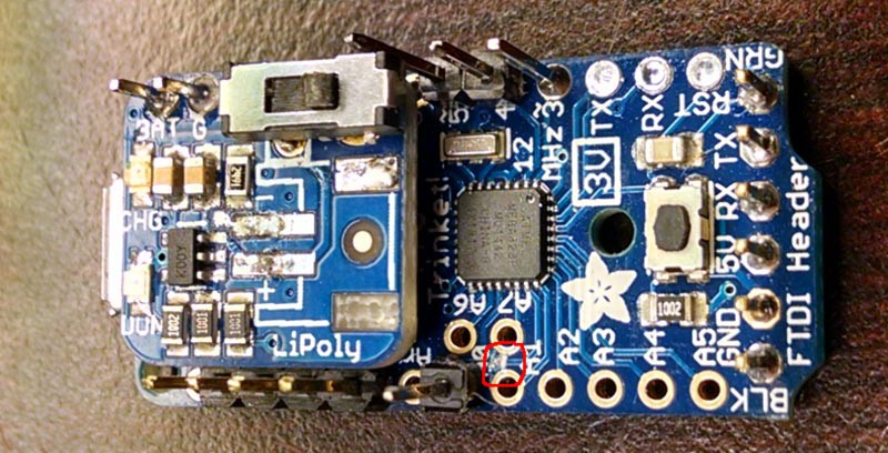
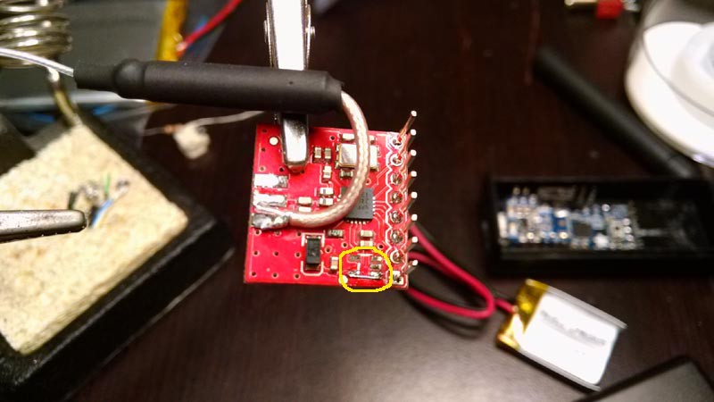
Highlight of where the trace to A0 was cut:
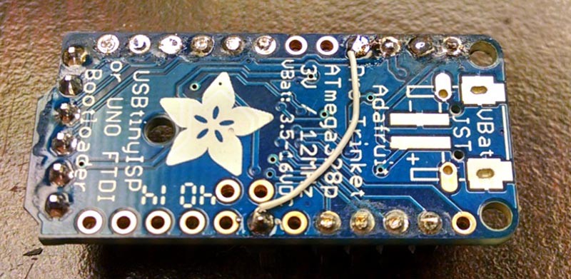
Jumper from 3.3v to A0 pin:
Assembled transponder, sans battery:

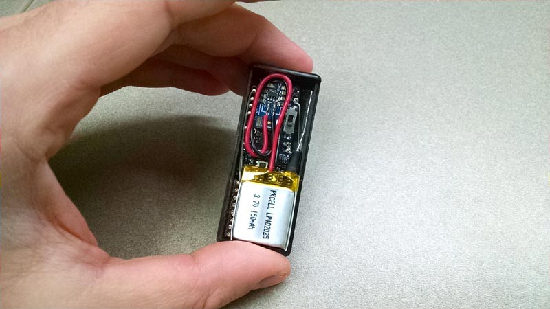
Assembled with battery:
Folded together, everything fits in the case, but barely:
Since I was providing regulated 3.3 volts to the transceiver, I removed its voltage regulator to reduce power consumption:
Keen eyes will also note that I added a switch to the LiPo backpack so I could hard reset the board if I need to (and I did often). I've also added a vibration switch (the small cylinder mounted cross-ways) so that motion can be detected in the future, but ultimately it is not necessary.
The following are links to the components used:
- Nordic Breakout Boards: https://www.sparkfun.com/products/705
- 2.4 GHz Antennas: https://www.sparkfun.com/products/145
- Trinket Pro 3v: https://www.adafruit.com/products/2010
- Trinket Pro LiPo Backpack: https://www.adafruit.com/products/2124
- 150 mAh LiPo battery: http://www.adafruit.com/products/1317
- Arduino Micro: https://www.adafruit.com/products/1086
- Vibration Switch: http://www.adafruit.com/product/1766
Schematics:
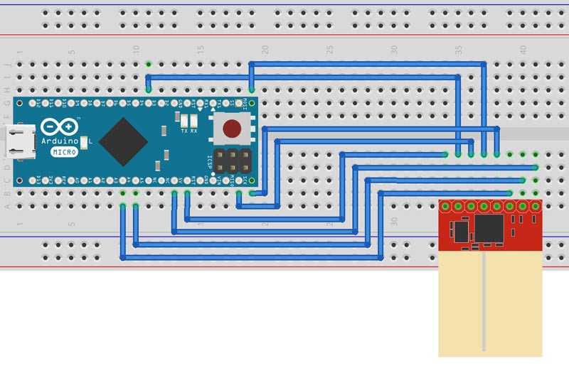
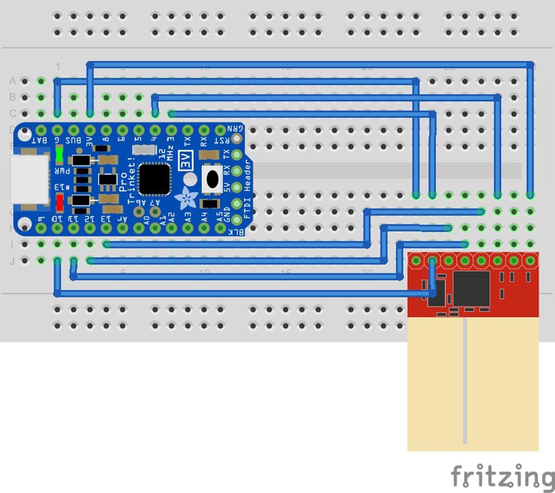
The schematics are pretty straight-forward. You'll be using the hardware SPI connections to communicate with the transceiver, connect MISO to MISO, MOSI to MOSI and SCK to SCK. The breakout boards are labeled underneath. For both boards we make sure to use a hardware interrupt pin on the microcontroller so we can take advantage of the quick response of that feature; this is important for accurate timing. The Sparkfun breakout board does have an on-board voltage regulator so you have some options on what you can use as a power source, please refer to their site to double check voltage ratings. Please refer to the definitions in the beginning of the code to identify the remaining pins.
Kudos to Fritzing for being a nice program for making these! http://fritzing.org/home/
Base Station:
Transponder:
NOTE: There is an error that shows pin 10 of the Arduino going to the IRQ pin on the transceiver. This is incorrect, pin 10 should lead to the CE pin.
Code:
The following code is written for the Arduino IDE. It is important to note that I am using direct port manipulation to start the transmission in the base-station and that this WILL need to be changed if you are not using an Arduino Micro or the same pins. You'll also notice that I often used binary to show the values being sent to register; this was largely due to preference as I could consult the datasheets for register values without relying on a binary to hex converter to handle the conversions. I've tried to make as many comments in the code as I reasonably could. If you have any questions, feel free to ask!
Base Station:
/*The following is code for the base station. This is the device that is left stationary and
serves as the point for collecting data and performing calculations. It configures the
transceiver, loads the transmit buffer (TX FIFO) and repeatedly sends a packet to the
transponder, measuring how much time (in clock cycles)elapses between the transmission of
the packet and the reception of the acknowledge packet from the transponder.The results are
filtered out using standard deviation and transmitted over serial.*/
#include <SPI.h> //include the SPI library to use for communicating with the transceiver
#define WRITE 0b00100000   // nRF24L01+'s write command
#define CLR(x,y) (x&=(~(1<<y))) //direct port manipulation: bring pin low (x= port y = pin# for the PORT!, not the board)
#define SET(x,y) (x|=(1<<y)) //direct port manipulation: bring pin high
// pins used for the connection with the sensor
// the other you need are controlled by the SPI library):
#define chipEnablePin A5 //PF0
#define chipSelectPin A4 //PF1
#define chipInterruptPin 3
#define DATAOUT 10//MOSI
#define DATAIN  11//MISO
#define SPICLOCK  9//sck
#define SLAVESELECT 8//ss
//code configuration variables
#define samples 600 //define how many samples we will take before performing calculations
#define minValue 13560 //smallest aloowable raw result from the test; serves as the minimum measured time
#define maxValue 13650 //smallest allowable raw result
#define sdFactor 100 //% to adjust standard deviant factor. Lower percentage results in tighter filtering
#define serialBaud 9600 //baud rate for serial connection
unsigned long starttime=0;
volatile unsigned long endtime=0; //cycles of timer1
unsigned long average = 0;
unsigned long stDeviation = 0;
unsigned long sum = 0;
unsigned int lowResultRejections=0; //log how many results were discarded that fell below the minimum
unsigned int highResultRejections=0; //log how many results were discarded that fell above the maximum
unsigned int numPoints = 0;
volatile byte stat = 0;
byte testResults[samples];
byte timercache = 0;
void setup() {
  Serial.begin(serialBaud);
  // start the SPI library:
  SPI.begin();
  SPI.setDataMode(SPI_MODE0); //clock polarity is 0, phase is 0
  SPI.setBitOrder(MSBFIRST); //set bit order
  SPI.setClockDivider(SPI_CLOCK_DIV8); //set SPI for max speed
  // initalize the  data ready and chip select pins:
  pinMode(chipEnablePin, OUTPUT);
  pinMode(chipSelectPin, OUTPUT);
  pinMode(DATAOUT, OUTPUT);
  pinMode(DATAIN, INPUT);
  pinMode(SPICLOCK,OUTPUT);
  //pinMode(SLAVESELECT,OUTPUT);
  pinMode(chipInterruptPin, INPUT_PULLUP);

  digitalWrite(chipSelectPin, HIGH);
  digitalWrite(chipEnablePin, LOW);
  //Configure nRF24L01+:
  //writeRegister(0x04, 0b00101000); //enable retransmit: wait 750 us between retransmit, attempt up to 4 times
  writeRegister(0x06, 0b00100110); //set for 250 kbps data rate and high power transmit
  writeRegister(0x05, 1); //0b00000100); //change channel
  //writeRegister(0x0A, 0x02); //set receive address of pipe0 (only writing LSByte, otherwise address is 5 bytes)
  //writeRegister(0x10, 0x02); //set transmit address (only writing LSByte, otherwise address is 5 bytes) receive pipe0 needs to be changed to this address for auto acknowledge to work
  writeRegister(0x11, 0b00000001); //set payload width for pipe 0, default is 0 (pipe not used)
  writeRegister(0x1C, 0b00000001); //set dynamic payload length
  writeRegister(0x1D, 0b00000100); //set dynamic payload length

  writeRegister(0x00,0b01001010); //CRC enabled, power-up, TX mode, disable RX_DR interrupt
  // give the transceiver time to set up:

  //configure timer1
  TCCR1A = 0b00000000; //disable comparators and run in normal mode (16 bit)
  TCCR1B = 0b00000001; //run at a prescaler of 0 to stop timer
  TCCR1C = 0x00; //disable force output compare

  delay(5000);
  writeRegister(0x04, 0b11101000); //enable retransmit: wait 1250 us between retransmit, attempt up to 4 times. For some reason this has to be written despite being previously called
  sendCommand(0b11100001); //clear TX FIFO
  writeRegister(0x07, 0b00110000); //clear TX status
  writeRegister(0b10100000, 0x00); //write blank value for pinging. Transponder will only change channel if value is over 0.
  digitalWrite(chipEnablePin, HIGH); //send enable signal to transmit
  digitalWrite(chipEnablePin, LOW);

  attachInterrupt(0, checkStatus, FALLING); //attach interrupt to #0 (pin 3) when it is pulled low
  Serial.println("Starting");
}
void loop() {

  delay(50);
  writeRegister(0x04, 0b10010000); //disable retransmit so we can accurately count dropped packets
  sendCommand(0b11100011); //reuse last transmitted payload
  lowResultRejections=0;
  highResultRejections=0;

  for(int x=0; x < samples; x++) {
    restart:
    delayMicroseconds(920); //helps stability of results, but needs to be a specific number, for some reason, to reduce outlier data
    stat = 0;
    timercache = TCCR0B; //store current state of timer register
    TCCR0B = 0x00; //pause timer 0 to prevent it's interrupt from triggering
    uint8_t oldSREG = SREG; //save results of interrupt register so they can be reinstated after global interrupts are re-enabled
    cli(); //disable global interrupts to make timing and trigger event as consistent as possible
    Serial.end(); //disable serial to marginally improve standard deviation (4%). Can be left out.
    GTCCR |= (1 << PSRSYNC); //reset general timer/counter control register to resync counters
    TCNT1 = 0; //reset timer 1 counter
    SET(PORTF, 0); //direct port manipulate the chip enable pin for more consistent results
    sei();
    SREG = oldSREG; //reinstate old interrupt register values
    while(stat < 1) { //stat must be a voltatile variable, otherwise the while loop freezes
    }
    CLR(PORTF, 0) ;//direct port manipulate the chip enable pin
    TCCR0B = timercache; //restore timer0
    Serial.begin(serialBaud); //restore serial

    if(stat==2) { //max_rt was triggered, restart measurement
        goto restart;
      }

    if(endtime > maxValue) { //limit the window of results; otherwise we collect some stray data at higher values
      highResultRejections++;
      goto restart;
    }
    if(endtime < minValue) {
      lowResultRejections++;
      goto restart;
    }
    testResults[x] = (endtime-minValue); //collect results into an array, subtract the minimum expected value so we can keep the values under a byte each (IE 13575-13600= 75)
    //serial string for PLX-DAQ
    //Serial.print("CELL,SET,A");
    //Serial.print(x+2);
    //Serial.print(",");
    //Serial.println(endtime);
  }
  sum = 0;
  for(int x=0; x<samples; x++) { //sum the test values so they can be averaged
    testResults[x] = testResults[x]*10;
    sum += testResults[x];
  }
  average = sum/samples;
  sum=0; //clear out sum so we can now use it to sum the squared difference from average, used for finding standard deviation
  for(int x=0; x<samples; x++) {
    sum += sq(testResults[x] - average);
  }
  stDeviation = sqrt(sum/samples); //find the standard deviation by finding the square root of the average of the squared difference from average (confused yet?)
  stDeviation = (stDeviation * sdFactor) / 100; //apply a factor to standard deviation, allows for tuning the filter
  sum=0;
  numPoints = 0;
  for(int x=0; x<samples; x++) {
    if(abs(testResults[x]-average) < stDeviation) { //sum the raw values that fall within standard deviation
      sum += testResults[x];
      numPoints++; //log the number of data points collected
    }
  }
  average = sum/numPoints; //find the standard deviation corrected average

  //serial string for PLX-DAQ
  Serial.print("DATA,");
  Serial.println(average);
  //Serial.print(",");
  //Serial.println(endtime);

  Serial.print(average);
  Serial.print(", ");
  Serial.print(numPoints);
  Serial.print(", ");
  Serial.print(lowResultRejections);
  Serial.print(", ");
  Serial.print(highResultRejections);
  Serial.print(", ");
  Serial.println(stDeviation);
}
void checkStatus()
{
  endtime=TCNT1; //read timer1 counter to find how many cycles have passed
  stat = readRegister(0x07,1);
  if(((stat & 0b00100000) >> 5) == 1) { //check for TX_DS interrupt
    writeRegister(0x07, 0b00100000); //clear TX_DS status
    stat = 1;
  } else if(((stat & 0b00010000) >> 4) == 1) { //check for MAX_RT interrupt
    stat=2;
    writeRegister(0x07, 0b00010000); //clear MAX_RT status
    sendCommand(0b11100001); //clear TX FIFO
    sendCommand(0b11100011); //reuse last transmitted payload
  }
}
//read the Status register of the nRF24L01+. We could use readRegister, but the transceiver automatically
//sends the status register on the first 8 bits of SPI so there's no need to send it a specific address:
byte readStatus() {
  byte result = 0; // result to return
  result = SPI.transfer(0xFF); // send a NOP value to read the status register
  return(result);
}
//Read from or write to register from the nRF24L01+:
unsigned long readRegister(byte thisRegister, int bytesToRead ) {
  unsigned long inByte = 0; // incoming byte from the SPI
  byte bytesRead = 0; //# of bytes to read from register
  unsigned long result = 0; // result to return
  digitalWrite(chipSelectPin, LOW); // bring the chip select low to select the device
  SPI.transfer(thisRegister); // send the device the register you want to read
  result = SPI.transfer(0xFF); // send a NOP value to read the first byte returned
  bytesRead++; // increment the number of bytes left to read
  while (bytesToRead > bytesRead) { // if you still have another byte to read
    inByte = SPI.transfer(0xFF); // continue to send a NOP value to read further bytes
    inByte = inByte << (8*bytesRead); // Bytes are loaded in least significant first. Take data in, shift it 8, 16, 24, etc bits over and add it to result
    result = result + inByte;
    bytesRead++; // increment the number of bytes left to read
  }
  digitalWrite(chipSelectPin, HIGH); // bring the chip select high to de-select the device
  return(result); // return the result
}
//Writes to register on nRF24L01+. Register addresses are handled by last five bits of command.
void writeRegister(byte thisRegister, byte thisValue) {
  byte addressToSend = thisRegister | WRITE; //combine write command and address to form one byte.
  digitalWrite(chipSelectPin, LOW); // bring the chip select low to select the device
  SPI.transfer(addressToSend); //Send register location
  SPI.transfer(thisValue);  //Send value to record into register
  digitalWrite(chipSelectPin, HIGH); // bring the chip select high to de-select the device
}
//Sends a command to nRF24L01+; can be done with write command, but this is slightly faster when a return isn't necessary
void sendCommand(byte theRegister) {
  digitalWrite(chipSelectPin, LOW); // bring the chip select low to select the device
  SPI.transfer(theRegister); //Send register location
  digitalWrite(chipSelectPin, HIGH); // bring the chip select high to de-select the device
}
Transponder:
/*The following is code for the transponder. This is the device carried on your person. It's
purpose is to configure the transceiver and keep the receive buffer (RX FIFO) empty. It can
also be used for power management, although that ability has not been coded yet.*/
#include <SPI.h> //include the SPI library to use for communicating with the transceiver
//Sensor's memory register addresses:
#define WRITE 0b00100000   // nRF24L01+'s write command
// pins used for the connection with the sensor
// the other you need are controlled by the SPI library):
#define chipEnablePin 10
#define chipSelectPin 4
#define chipInterruptPin 3
#define DATAOUT 11//MOSI
#define DATAIN  12//MISO
#define SPICLOCK  13//sck
#define SLAVESELECT 10//ss
volatile byte stat = 0;
void setup() {
  Serial.begin(9600);
  // start the SPI library:
  SPI.begin();
  SPI.setDataMode(SPI_MODE0); //clock polarity is 0, phase is 0
  SPI.setBitOrder(MSBFIRST); //set bit order
  SPI.setClockDivider(SPI_CLOCK_DIV2); //set SPI for max speed
  // initalize the  data ready and chip select pins:
  pinMode(chipEnablePin, OUTPUT);
  pinMode(chipSelectPin, OUTPUT);
  pinMode(DATAOUT, OUTPUT);
  pinMode(DATAIN, INPUT);
  pinMode(SPICLOCK,OUTPUT);
  pinMode(SLAVESELECT,OUTPUT);
  pinMode(chipInterruptPin, INPUT);
  digitalWrite(chipSelectPin, HIGH);
  digitalWrite(chipEnablePin, LOW);
  //Configure nRF24L01+:
  writeRegister(0x04, 0b00010011); //enable auto-retransmit:address, value
  writeRegister(0x06, 0b00100110); //set for 250 kbps data rate and high power transmit
  writeRegister(0x05, 1); //change channel
  //writeRegister(0x0A, 0x02); //set receive address of pipe0 (only writing LSByte, otherwise address is 5 bytes)
  //writeRegister(0x10, 0x02); //set transmit address (only writing LSByte, otherwise address is 5 bytes) receive pipe0 needs to be changed to this address for auto acknowledge to work
  writeRegister(0x11, 0b00000010); //set payload width for pipe 0, default is 0 (pipe not used)
  writeRegister(0x1C, 0b00000001); //use dynamic payload length
  writeRegister(0x1D, 0b00000100); //use dynamic payload length

  writeRegister(0x00,0b00111011); //CRC enabled, power-up, RX mode, mask TX interrupts
  delay(100); // give the transceiver time to set up
  attachInterrupt(1, checkStatus, FALLING); //attach interrupt to #1 when it is pulled low
  digitalWrite(chipEnablePin, HIGH); //chip enable needs to be high for transceiver to receive
}
void loop() {

  delay(60);
    if(stat = 1) {
      if((readRegister(0x17,1) & 0b00000001) == 0) { //check that there is data in the RX FIFO, continue to read and clear IRQ until RX FIFO is empty
        readRegister(0b01100001, 1); //read RF FIFO to clear it out
        writeRegister(0x07, 0b01110000); //clear interrupt status once RX FIFO has been read out
       }
      if((readRegister(0x17,1) & 0b00000010)>>1 == 1) { //check if the RX_FIFO is full, sometimes this causes a hang-up and it needs to be cleared to resume receiving
        sendCommand(0b11100010); //flush RX_FIFO
       }
       stat = 0;
    }

}
//interrupt for checking and clearing the status register of the nRF24L01+:
void checkStatus()
{
  stat = 1;
}
//read the Status register of the nRF24L01+. We could use readRegister, but the transceiver automatically
//sends the status register on the first 8 bits of SPI so there's no need to send it a specific address:
byte readStatus() {
  byte result = 0; // result to return
  result = SPI.transfer(0xFF); // send a NOP value to read the status register
  return(result);
}
//Read from or write to register from the nRF24L01+:
unsigned long readRegister(byte thisRegister, int bytesToRead ) {
  unsigned long inByte = 0; // incoming byte from the SPI
  byte bytesRead = 0; //# of bytes to read from register
  unsigned long result = 0; // result to return
  digitalWrite(chipSelectPin, LOW); // bring the chip select low to select the device
  SPI.transfer(thisRegister); // send the device the register you want to read
  result = SPI.transfer(0xFF); // send a NOP value to read the first byte returned
  bytesRead++; // increment the number of bytes left to read
  while (bytesToRead > bytesRead) { // if you still have another byte to read
    inByte = SPI.transfer(0xFF); // continue to send a NOP value to read further bytes
    inByte = inByte << (8*bytesRead); // Bytes are loaded in least significant first. Take data in, shift it 8, 16, 24, etc bits over and add it to result
    result = result + inByte;
    bytesRead++; // increment the number of bytes left to read
  }
  digitalWrite(chipSelectPin, HIGH); // bring the chip select high to de-select the device
  return(result); // return the result
}
//Writes to register on nRF24L01+. Register addresses are handled by last five bits of command.
void writeRegister(byte thisRegister, byte thisValue) {
  byte addressToSend = thisRegister | WRITE; //combine write command and address to form one byte.
  digitalWrite(chipSelectPin, LOW); // bring the chip select low to select the device
  SPI.transfer(addressToSend); //Send register location
  SPI.transfer(thisValue);  //Send value to record into register
  digitalWrite(chipSelectPin, HIGH); // bring the chip select high to de-select the device
}
//Sends a command to nRF24L01+; can be done with write command, but this is slightly faster when a return isn't necessary
void sendCommand(byte theRegister) {
  digitalWrite(chipSelectPin, LOW); // bring the chip select low to select the device
  SPI.transfer(theRegister); //Send register location
  digitalWrite(chipSelectPin, HIGH); // bring the chip select high to de-select the device
}
Thanks for your interest!
-Eric J. Herbers