 Jithin
Production version here : This project has been adapted for mass production, and packaged along with an SBC running the necessary software.
The software has over 70 different experiments, and a custom experiment designer.
Quarterfinal Video
Project logs!Non contact, Short range position sensing. 10um resolution
Amplitude modulation with AD633
Calibrating with a 24-bit ADC and a Keithley 2100 multimeter
Developing a 24-bit ADC, 18-Bit DAC add-on
Wireless Node A . Wireless Node new
Plug and play arduino sensors for science experiments
Designing Laser cut enclosures
Prototype #4 - 555 timers, IR sensors, wavegens.
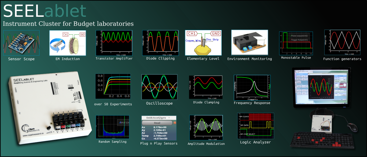
Here are a few short clips of some of the experiments carried out using this tool
A) Measuring the forward threshold voltage of a diode, and studying the effect of temperature on the band gap.
Several IV plots were obtained and plotted along a third axis as a 3D line plot. The diode was heated somewhere in the middle of the acquisition ( notice the inflection point ), and this added thermal energy changes the band gap, causing the threshold voltage to drop.
B) Characterizing an active band pass filter
An op-amp based multiple-feedback band pass filter was made with values calculated from simulation tools available at http://sim.okawa-denshi.jp/en/OPtazyuLowkeisan.htm . The transfer function was experimentally determined using the device's waveform generator, oscilloscope, and curve fitting routines from scipy.
*The PIC1572 based PWM waveform generators have since been replaced with a high resolution DDS, the AD9833.
C) Supporting a variety of SPI/I2C/UART protocols allows accomodating a variety of sensors in a plug and play fashion. A wide range of modules such as accelerometers, gyros, doppler radars, weighing sensors etc have been tested.
D) Inexpensive wireless nodes with unique addresses can be used to implement mesh networks for data collection. The wireless nodes are configured to use 3 byte addresses, and this leaves plenty of room for multiple sensing points/parameters.
The following is a demo with the MPU-6050( accelerometer + gyro + temperature sensor) used in the above video, except here the data transmitted back is being used to orient a 3D object in real time. IC temperature decides the object shading gradient.
The third prototype was presented at http://Scipy.in, a conference on scientific python held at IIT Bombay. The abstract can be found Here
Several changes have been made since.
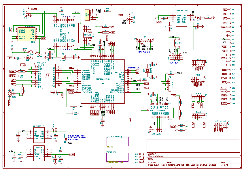
System Design : Refer to the Cover photo for flow chart
Hardware:
The following is a list of currently implemented features
- Four Channel Oscilloscope
- 10-bit resolution. 1Mohm impedance. 1MSPS sampling. Selectable level triggering.
- Up to 10K samples
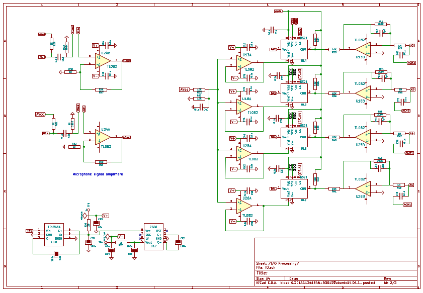
- Up to 14 different selectable inputs with various input ranges and amplifications
- CH1-CH4 . +/- 16.5V down to +/-500mV .( read via 1x-32x Programmable gain amplifiers) . AC coupling available.
- CH5-CH9 (0-3.3V . Up to 32x analog gain) . High impedance input of 1e13 ohms(taken from datasheet. Circuit layout may alter this value )
- IN1 - Connected to Charge Time measurement Unit
- 5V usb supply monitoring
- +9V supply output monitoring
- Programmable constant current source output monitoring
- Interrupt driven acquisition. Frees up device CPU for accepting additional commands and processing them based on when the oscilloscope permits. Unless the scope is running at maximum capture speed, additional measurements and control tasks can be executed. The LCR circuit response experiment is an example that uses this
- 12-bit voltage measurement with 16 sample averaging on all the above channels. Waveform capture with up to 400KSPS.
- Four Channel Logic Analyzer
- Selectable inputs ID1,ID2,ID3,ID4, and CH4( internal comparator)
- 32-bit counters for 2-channel acquisition ( up to 67 seconds between each level change at maximum resolution. 16-bit counters for four channel acquisition (up to 1mS delay between each level change before overflow occurs during maximum resolution. Clock can be scaled down to increase this delay to 250mS
- Edges to be recorded can be selected for each input. [ Falling edges, rising edges, all edges etc.]
- Edge triggering via any of the inputs as well as analog input CH4 via a configurable internal comparator
- Driven entirely by DMA. This essentially means that the device is free to accept other commands once the Logic Analyzer has been started. It runs in the background, independent of the CPU.
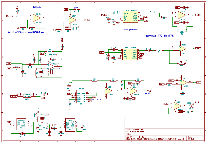
- 2 x 28-bit phase correlated Sine/Triangular Waveform generators with bipolar outputs
- Based on AD9833 DDS . Allows Sine/Triangular outputs
- Default input Clock of 8MHz results in about 0.03Hz resolution from 0MHz-1MHz. The Input clock can be reduced further in order to achieve higher resolution (1MHz => 0.004Hz resolution ).
- 12-bit control over phase difference between each
- Two frequency registers per wavegen. The DDS can be instructed to switch between these two for applications such as Frequency Shift Keying(FSK).
- Amplitude control via an external potentiometer (0-+/-3.3V)
- 4 x Digital outputs which can also be configured as PWM outputs with phase and duty cycle control. Can also be used to control up to four servo motors.
- Frequency Counter Up to 64MHz
- 3 x 12-bit Programmable Voltage sources with ranges 0-3.3V, +/-3.3V, +/-5V.
- 1 x 12-bit Programmable Constant Current source up to 3.3mA
- Capacitance meter from a few PicoFarads (Using the CTMU [Constant Current Charging] ) , up to a few microFarads via constant voltage charging.
- Inductance meter that uses a tank circuit with a 1nF capacitor to generate a corresponding frequency which is then measured by the frequency counter to calculate the inductance. A solenoid with a movable core can be used as a high precision position sensor here ( resolutions < 10 microns ) .
- Serial Peripheral Interface (SPI)
- Full software control over frequency ( Up to 32Mhz ), and modes
- 8-bit / 16-bit write
- 2-Dedicated chip selects. Four more can be leveraged using the digital outputs
- Tested with a variety of add-on boards and sensors such as MCP6S21(PGA), AD9833 (waveform generator) , NRF24L01+ ( 2MbPS digital radio with up to 5-BYTE address, auto-acknowledge and 32 byte payloads. Wireless Add-ons planned ) etc
- Inter Integrated Circuit (I2C) port
- Configurable clock frequency
- Port scan
- Tested with a variety of sensors such as MPU6050(accel+gyro+temp sensor), HMC5883L(magnetometer), BMP80 (Altimeter), MCP4728(12-bit DAC), SSD1306(128x64 OLED).
- Provision for ESP-12 WiFi on the circuit board . This requires reprogramming the ESP8266, as well as disconnecting the MCP2200 USB-Serial convertor. Addditional 5V power supply must be provided either from a bench top, or a USB charger.
- 24-bit RGB status indicator LED with daisy chain output for driving additional WS2812 units
- 500mA polymer fuse to protect USB ports
- High stability Voltage reference.
- +/- 9V outputs for powering bipolar devices
- TP4056 lithium ion charging IC
- PCB pads for directly connecting the device with a raspberry pi either via its UART output, or by dedicating one of its four USB ports
- The Firmware includes hardcoded functions to interface with the following sensors/hardware that can be connnected to the expansion slots
- HX711 24-bit weighing sensor - It has two fully differential channels with 32x,64x,128x Programmable gain amplifiers.
- NRF24L01+ 2,4GHz radio - Capable of sending packets at speeds up to 2MbPS, with 5 byte addressing, and automatic error correction and acknowledge. This will be instrumental in implementing wireless sensor networks
- AM2302 Humidity + Temperature sensor
- TCD1304 - Linear optical array with 1348 pixels, and customizable integration times
- HCSR04 distance sensor
Software:
- Python Library. A rough draft of the Programmer's manual can be found at http://pythonhosted.org/LabtoolSuite/interface.html
- Qt based GUIs for oscilloscope, logic analyzer, peripheral control, data streaming etc are part of the package.
- Several GUI are being developed towards setting up a standard set of experiments for beginners.
- Framework for quickly setting up dedicated GUIs .
- Python takes care of third order calibration, curve-fitting, and other complex data analysis
What doesn't work:
WiFi support! It has only been vaguely tested with a crude oscilloscope webapp made with jquery.flot , but has not been developed with the latest SDK.
Licenses
Python - GNU GPL compatible
Python-qt4 - GPL ( As long as everything built on top of it is also open-source )
PyQtGraph - MIT licence
iPython - BSD License
All Python based apps and software designed for this project : GPL-v3
Schematics - GPL-v3
Firmware - Closed Source Until further notice.