 Jithin
Production version here : This project has been adapted for mass production, and has been packaged along with an SBC running the necessary software.
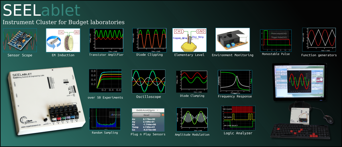
The software has over 70 different experiments, and includes a custom experiment designer.
What's this all about... And what is the problem you're trying to solve?
____Shortage of funds restrict teaching labs, and stifle creativity.
A ) Learning through experimentation offers a much clearer view of phenomena than merely trusting theory.
But, Setting up a well equipped teaching lab for science and electronics can turn out to be a very expensive affair.
Each student will require a minimum set of instruments comprising of multimeters, scopes, various sensors, and so on, in addition to the experiment specific hardware.
____Accuracy.
B ) These instruments must also be reasonably accurate for the results to tally with theoretical predictions such as the time constant of an oscillator, or the value of acceleration due to gravity.
____Usability
C) A common, program based interface to access all the instruments associated with a particular experiment allows much greater flexibility and control. A primary requirement for this is that the instruments must all use well documented control inputs interface-able with a computer. Unfortunately, documented control interfaces are rare in the low-end market.
What is the solution being attempted ( Or, What are your goals for this project )?
____Solve all the above, and balance cost with performance!
This project can be called a base board with an essential set of carefully calibrated instruments with design focused on being able to support a variety of limited audience, niche instruments ( Think high resolution ADCs, DACs, Signal modulators , and wireless modules ) . Significant room for improvement has been left in the form of an expansion slot. Here's an example add-on board for a 24-bit ADC used for calibration.
___How?
A processor with a fairly powerful set of peripherals is complemented with a variety of analog and digital tools. The setup connects to a computer via USB, and acts as a slave device that measures or controls as per instructions sent by the user via Python programs or graphical apps.
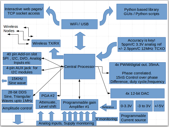
An accurate, temperature compensated clock source is chosen as the reference for the digital instruments, and a low-drift voltage reference is chosen for maintaining the predictability of analog instruments. These two together ensure that readings stay consistent over a reasonable temperature range .
The device is then calibrated against professional instruments that rectify non-linear behaviour as well as offsets and slopes in order to squeeze out maximum performance.
___Choosing an interface
Python was chosen as the main interface language owing to the vast computational and visualization resources it has. These are essential for analysing acquired data and extracting physical parameters. It's also quite easy to learn, and since quite a few schools already teach it, we are but one step away from bridging the gap between software based learning, and experiment oriented methods.
*Additional interfaces: Standalone modes based on a plug-and-play display, as well as WiFi are part of the plan.
____What if you just can't write code, but are quite adept at designing experiments.
Several graphical interfaces with control and display widgets have already been designed. Check out the videos at the bottom of the page.
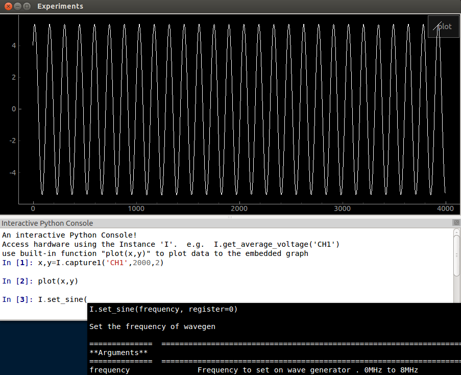
If you're open to trying a few simple lines of code, the console app features an embedded iPython console that autocompletes as well as displays documentation. It also has a ready to use graph that's accessible with a single function call.
As far as developing experiment specific apps is concerned, a few are ready, and a common framework has been developed in order to facilitate contributions by reducing code sizes.
____Is it damage proof?
Users will often make wrong connections, and the design must withstand reasonable assaults.
A few measures have been taken in this regard.
- A 500mA poly-fuse is part of the main USB input. This fuse auto-repairs when the offending load is removed.
- The DAC channels are specified as short-circuit proof, and the outputs will simply load the bipolar power supplies, causing their voltages to drop .
- Analog inputs are all high impedance, but exceeding voltage limits in either direction on multiplexed channels(CH1,CH3-7,I2V ) will distort the rest of the multiplexed channels. This will not damage the unit within generous limits.
So what can you kill ?
If you're not excessively harsh, only the outputs broken out into the expansion slot are sensitive. Most of these come directly from the main processor, and you should be as careful with these as you are with your Arduino's outputs.
The CAP input is directly connected to the Charge Time Measurement Unit of the processor, so please discharge any high voltages that may be present on capacitors before plugging them in.
____The software., Associated licenses.
All client software is Python based, and no proprietary modules have been used. These include Python,Scipy,Numpy, Python-Qt4 , and PyQtGraph . All these work on multiple platforms, and are chosen to facilitate ports in the near future.
Licenses
- Python - GNU GPL compatible
- Python-qt4 - GPL. Also requires that apps using PyQt4 be similarly open-sourced.
- PyQtGraph - MIT licence
- iPython - BSD License
- All Python Modules and Apps developed specifically for the vLabtool are hosted on github, and licensed with GPL-V3
- The package is also hosted on PyPI, and is registered as vLabtool.
- The Programmer's manual is auto-generated with Sphinx, and is live here
- The firmware is not being released for now. This also includes the wireless nodes since adding support for sensors is done on the Python side of things.
What Platforms are recommended?
The toolchain has been developed and tested on Ubuntu versions>=12.04 . It has also been tested on Raspbian Wheezy.
Installing the toolchain ( Please Check the Build instructions section )
_dependencies (Might be incomplete. Full testing pending):
sudo apt-get install python-qt4 python-opengl python-qt4-gl python-scipy python-numpy ipython-qtconsole
A) From PyPI
sudo apt-get install python-setuptools
sudo easy_install vLabtool
B) From Github
git clone https://github.com/jithinbp/vLabtool.git
cd vLabtool
sudo python setup.py install
-------- The above steps install the Python module as well as several Apps that can be accessed directly from a shell.
Current list: vLabtool-scope, vLabtool-stream, and several others, all prepended with 'vLabtool' .
Quick demo video of the oscilloscope and waveform generator functionality of the vLabtool being compared with professional equipment
Demo Video of the phase correlated PWM generators and Logic Analyzer.
Square waves generated at SQR1-4 are monitored using ID1-4 . The shape of the waveforms are first shown in the analog section.
The Logic Analyzer functionality is primarily aimed at science experiments where fast events may need to be recorded. Such as the speed of a projectile fired through a light barrier, or a ball bouncing on a contact switch pad.
Accuracy comparison of the frequency counter with inputs up to 10MHz.
Highlights: Using the Fox924b TCXO as the digital reference for the vLabtool really paid off. The maximum error is 2.5ppm as opposed to the 30ppm crystal that was previously being used.
The GUI shown in the video is vLabtool-stream, and can be run from a terminal. It accepts any input function defined in the python module of the vLabtool as long as the return value is a number
Voltmeter accuracy test video
Various voltages were generated using the PVS outputs, and monitored with professional equipment as well as the various analog inputs of the vLabtool. Detailed project logs HERE and here
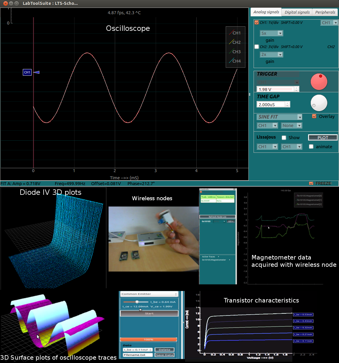
Wireless Nodes demo video. This device has an NRF24L01+ radio on board, and wireless modules have been prepared for data acquisition from multiple points for which wires may not work. For example, the motion of mechanical setups such as torsion pendulums can be monitored with a compass module(HMC5883L) plugged into a wireless node placed on it.
The output of a magnetometer and an accelerometer is shown in the video.
You might want to slow down the video, or try to keep up. I messed up the settings of RecordMyDesktop.
Project Logs
- NRF24L01+,PIC16F1618 based wireless nodes for multi-point acquisition and control
- Add-on board: 24-bit ADC, 18-bit DAC
- Standalone Mode using a 128x64 OLED
- Controlling Daisy Chained Addressable LEDs [WS2812B]
- Designing an enclosure with SolidWorks and KiCAD for 3D printing, and Laser Cutting
- Building Blocks: Project logs dealing with the design of each tool present on the base board
- Calibrating the ADC for maximum accuracy from all analog inputs.
- GUIs for experiments. Embedded Videos
- Calibrating DACs
Detailed Summary- A low cost swiss army knife of measurement and control instruments for learning through experiments
- 12-bit Analog inputs with programmable gains, independent 12-bit offset control, and maximum ranges varying from +/-16V to +/-100mV. Several unipolar, high impedance channels and power supply monitoring channels are also available.
- Frequency counter tested up to 32 MHz. MCU supports up to 64MHz, but needs verification.
- 4-channel Logic analyzer with 15nS resolution, and DMA based approach that does not block user access to other functions while it acquires data. Independent function calls available to measure time differences between specified level changes on different digital inputs.
- 2-channel oscilloscope capable of monitoring all the above mentioned analog inputs at 1MSPS. Interrupt driven implementation frees up CPU to run other commands received during acquisition.
- 28-bit , 0 - 2MHz Sine, triangular waveform DDS [AD9833] . Maximum amplitude +/-4V , attenuable to a few ten millivolts via manual control knob present on the hardware.
- 12-bit Constant Current source. Maximum current 3.3mA [subject to load resistance]. voltage monitoring must be carried out externally to check for saturation.
- up to four phase correlated PWM outputs with maximum frequency 32MHz, 15nano second duty cycle, and phase difference control.
- Current to voltage convertor(+/-3.3mA) with up to 32x gain, and independent offset control.
- SPI,I2C,UART outputs that can be configured and controlled entirely through Python functions.
- Onboard NRF24L01+ transceiver for wireless data acquisition.
- 5V,3.3V,+/-8V power supply outputs.
- Graphical Interfaces for Oscilloscope, Logic Analyzer, streaming data, wireless acquisition, and several experiments developed that use a common framework which drastically reduces code required to incorporate control and plotting widgets.
- Standalone Mode that uses a 128x64 OLED to display a few basic measurements.
Notes:
An ESP-12 wifi module can also be used in place of a USB connection, but a separate 5V power supply will be required. This will either simply provide a TCP socket, or host standalone web pages with control widgets (Work in progress ).
Space for a CH240G USB-Ser has been left as an option in place of the more expensive MCP2200, but has not been tested so far.
Prototypes are being calibrated against a 6 1/2 digit DMM from Keithley instruments. A separate 24-bit ADC board with its own stable reference has been developed and calibrated for future use.
A +/-2.5 ppm temperature compensated crystal oscillator from Fox is used to maintain the accuracy of digital instruments ( frequency counter, waveform generators, logic analyzer,etc )