 Radu Motisan
Intended as open source for those who want to build their own dosimeter with their own tools, this is an IOT device that can take several sensors and have the data centralised online. The readings are accessible via a RESTful API, or by connecting directly to the KIT1 unit, in the local LAN. This is useful when you want to monitor several locations, and plot charts or analyse the data.
By default it comes with a SBM20 tube to measure Gamma radiation and has an extension slot (v1.2.105) to add additional sensors. The code on GITHUB offers support for the Bosch BME280 sensor by default.
With the integrated Ethernet connectivity will send all measurements automatically via the Internet, to the uRADMonitor server, or to any backend you want. Add a battery and it can also be used as a portable dosimeter, showing all measurements on the LCD.
The community helped improving the design, with very many custom variants proving the utility of this IOT device, see the pictures in this project log.

Version 1.0
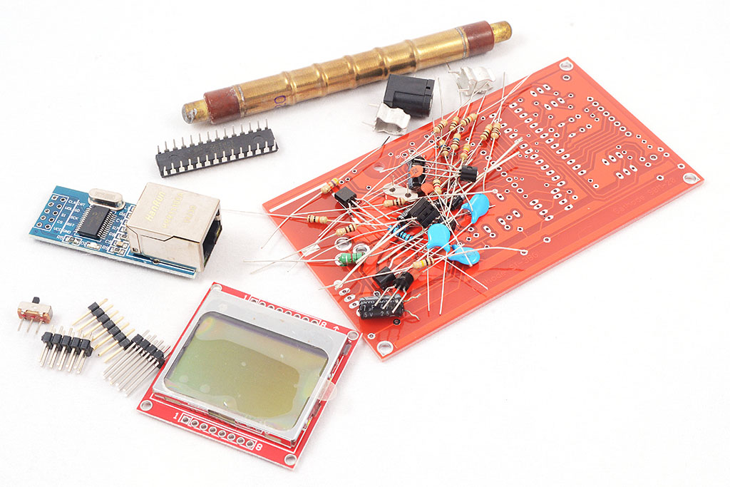
Finally an open source compact radiation dosimeter, that has an LCD and thus allows mobile use, but also comes with an Ethernet adapter so it can do radiation monitoring (uRADMonitorcompatible). This is a DIY Geiger Counter Kit, named the uRADMonitor KIT1, designed due to popular demand. Now, all those asking for a uRADMonitor Kit have a nice alternative in this device. This circuit uses a single layer PCB and only trough hole components, making the construction so much easier for all the DIY enthusiasts.
The video shows the first prototype of version KIT1.0, built using the toner transfer method. As said, it was designed using through hole components, on a single layer PCB board.
Version 1.1:
 What's new in 1.1 is that this revision replaces the ferrite transformer in the high voltage inverter, with a ferrite choke circuit, so the complicated part of building the custom transformer is gone. You can build this using shelf components, and the Gerbers files for making the PCBs are also included. Just send the gerbers to your favorite PCB manufacturer, get the BOM and start soldering. With just a couple of components, you'll have an excellent dosimeter of wonderful performance.
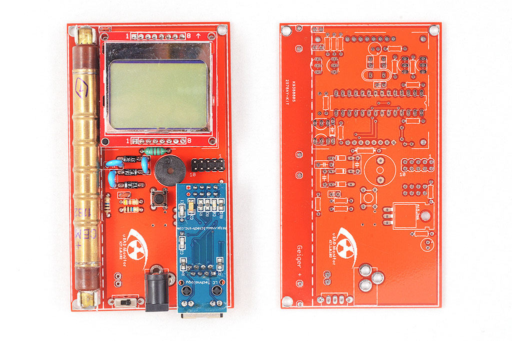 There's a slot to mount a SBM-20 Geiger tube, a connector for the Ethernet module and one for the Nokia 5110 LCD screen. Both the LCD and the Ethernet adapter can be removed, allowing you to configure the final device: make that a portable dosimeter, a monitoring station or both. A speaker provides audible signals, including clicks and alarm, and a push button permits user interaction with the software. There are two pins at the bottom side that can be used to connect a 3V battery (two AA in series) or the unit can be powered using the DC connector, via a LM317 regulator and then it takes in any voltage in the 5-9V interval. The entire board runs on 3V, and the high voltage inverter boosts that up to 380V, configurable in software up to 600V if a different Geiger tube needs to be used.
The server infrastructure
uRADMonitor is Big Data. Hundreds of detectors worldwide are collecting measurements every minute, and the server deals with millions of entries in its database every day. The database holding KIT1 data was designed for efficiency: only the minimum data goes in. One reason for open sourcing was to allow customising the KIT1 units with additional sensors. We had to adapt the server backend in this regards, and now there’s an expandable list of parameters that can be uploaded.
Then there’s the data accuracy which needs to be guaranteed to a reasonable degree by supervising and testing the hardware, something impossible with open, remote constructions. Making the server decide if the data is genuine or just some random useless bits was not an easy task.
Last but not least, here comes the security. Initially, open source can be a source of vulnerabilities of the exposed system. We had to make sure the new open communication protocol is safe to use. We’ve implemented API Authorisation for all data uploads generated by the Open Source KIT1 units. Go to the dashboard, and create an account if you don’t have one already. You’ll need to use the user-id and the user-key listed there with your new uRADMonitor KIT1. If you go for the stock firmware, then you won’t need them.
Please welcome the Open Source uRADMonitor KIT1.2.105
With so many changes on the server backend, I had to improve the KIT1 circuit and PCB. I tried to add many of the suggestions received on the forum. From now on however, feel free to fork the original Github repository and do whatever you like with this open design. The new version is KIT1.2.105, and you can see the first design images below:
The new design is more compact, so if you want to add a battery you’ll have more space. The arrangement of some components has been optimised and the regulator becomes the single SMD component on this otherwise exclusively through hole components PCB. As soon as we get the first of the new PCBs, we’ll add more pictures with them.
Using the KIT1.2
Once your KIT1.2 circuit is complete, download the firmware code from Github. In config.h add your user-id and user-key from the dashboard.
Compile the code, and write the HEX to your board, using a 6 PIN ISP connector. For the fuse settings, if you followed the original design, you’ll need to set the external 8MHz crystal, and make sure the EESAVE fusebit is set.
avrdude -p atmega328p -c usbasp -U lfuse:w:0xDC:m -U hfuse:w:0xD7:m
avrdude -p atmega328p -c usbasp -U flash:w:uradmonitor-KIT1-EXP.hex:i
Your unit will receive a device ID allocated dynamically by the server. If you want to use a BME280 sensor, there is code already in place. Just make sure the USE_BME280_SENSOR is set in the config file.
Adding more sensors
With the extension port that exposes I2C, UART and power, you have the possibility to add a large number of additional sensors. Add the sensor driver code, and do the sensor reading in app/data.cpp and app/data.h initSensors() and readSensorsSlow(). To send the data online, see the code file misc/expProtocol.h for parameter IDs and how they are used in uRADMonitor.cpp line 350. More parameter IDs will be added based on demand. All previous KIT1 hardware versions are compatible with the new firmware. For any questions and assistance, use the forum.
To compile the code, please use Eclipse and the AVR Crosspack plugin as well as the AVRDude software. For uploading the HEX code, you can use the versatile usbAsp programmer configured for 3.3V!
License
uRADMonitor KIT1 is released under GPL v3 or newer. Read the license terms here. For custom licensing, contact us. Download PCB layout, Gerber files and firmware source code here.