Laser cutting with this robotic arm:
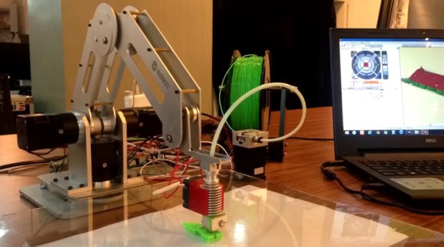
Soldering with Dobot robotic arm:Robotic arm 3D printer:
Do some dangerous experiments and stir solution with Dobot robot arm:
Show something really crazy: Can you believe doing this with Dobot?
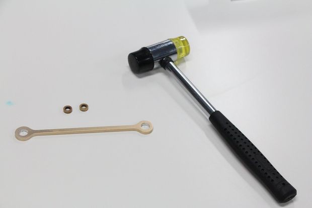
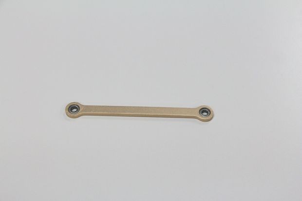
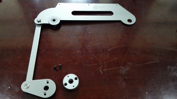
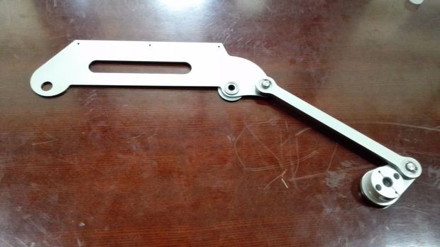
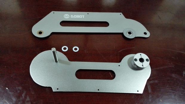
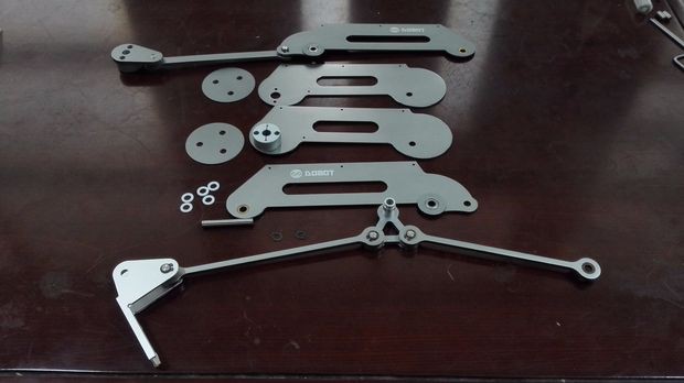
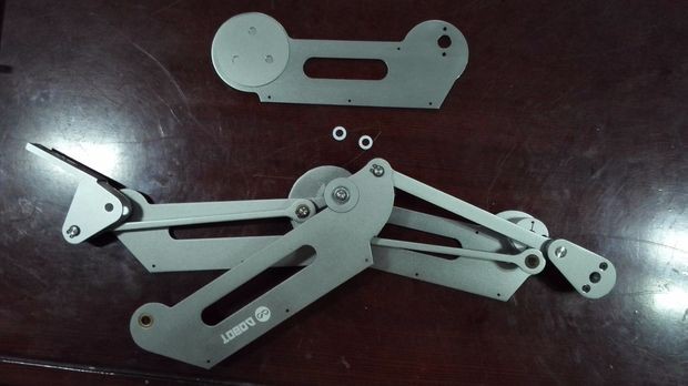
Step 1: Prepare materials
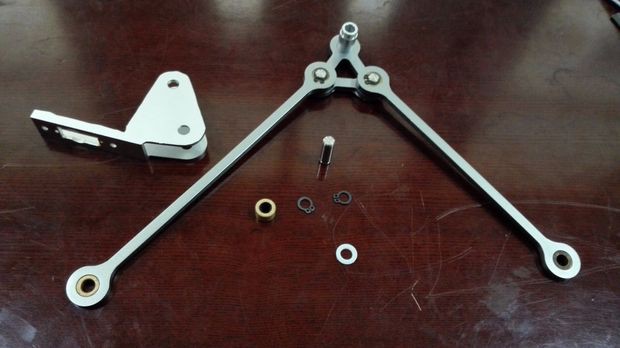
The pictures above show all components you need.
List:
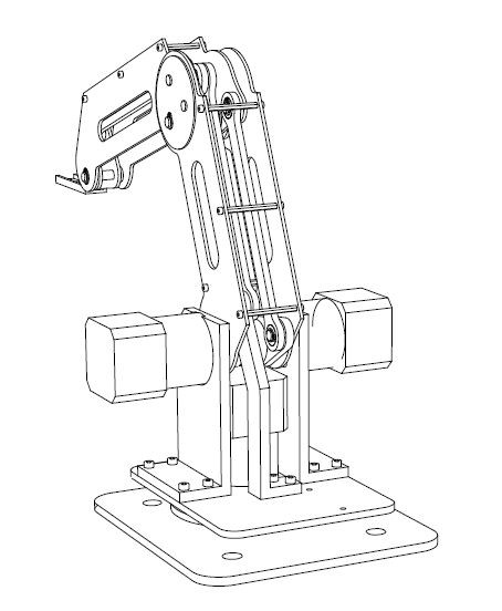
main arm
the axis
Arduino mega2560 board
three step motors
bearing specification: 6*12*4
copper gaskets specification:t hickness 1.5mm
M3 nut
M5 bolt
M2*8 inner hexagonal head bolt
M2.5*12 inner hexagonal head bolt
M3*10 inner hexagonal head bolt
...

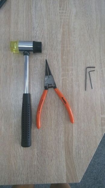
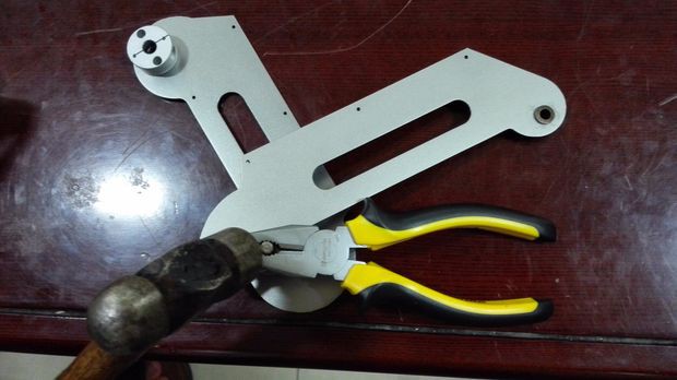
Step 2: Prepare the tools
You need to prepare the tools below:
A hammer
Four allen wrenches including M4, M3,M5 and M2
Some glue and a needle-nose plier which is used to open the M4 snap
Step 3: Add the bushings and bearing to three axes
Add the 6*10*8 copper bushings to the A axis and add the 6*10*4 copper bushings to the B axis and then add the 6*12*4 bearings to the C axis. Be careful when you add these components to the axes, you must be sure your bushing and bearing are vertical to the axes or you will get an askew axis with bushings. Maybe you need to use the hammer to knock the bushings and bearings slightly. After finishing these parts, add some glue to the contact surfaces between axes and bushings or bearings to ensure it won't have any sliding between axes and bushing or bearing.
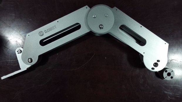
Step 4: Connect the three axes with the triangle linking part
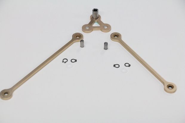
Then we connect the three axes with the triangle linking part. First, add the φ6*9 mm axis to the triangle linking part and add the sleeve to the linking part.You should be careful with the direction of the sleeve. Second, add a 0.7mm nylon washers to the axis. Third, respectively add the A and B axis with bushings to the linking part and you must be careful for the direction of the two axes. The right direction of the axes is showing on the picture. Then we respectively used two snaps to fix the A and B axis. If you have any questions, you can watch this Dobot explosion diagram below:
Step 5: Connect the parallel support part with the B axis
Use two M3*10 screws to fix the small block with the main part of parallel support. Add the φ6*14 axis to the other side of A axis and add a 0.7mm washer to it. After finishing these, add the parallel support to the right side then we use two snaps to fixate it.
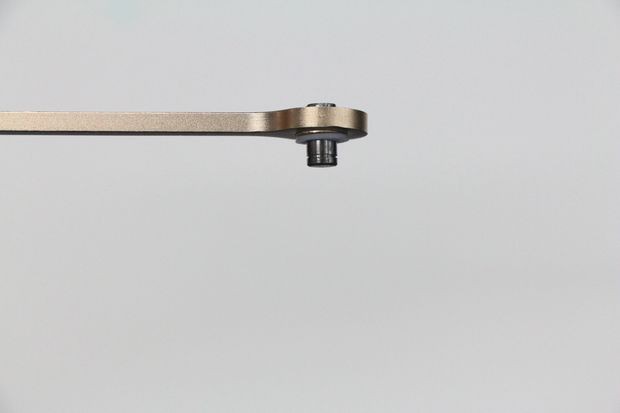
Step 6: Connect the head of the arm with the other side of A axis
First, we set the head of the arm with the other side of A axis and add two0.7mm washers into it. Then we put the 6*10*6 copper sleeve on the right position and add the φ6*18 axis through the hole. What does it mean by right position? It means that when you look at the arm in front of you, the copper sleeve is in between the left side of the A axis and right side of the arm head, and the two washers are in the other side. Then we fix them with two snaps again.

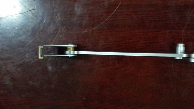
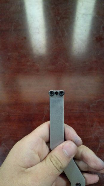
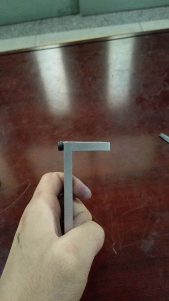
Step 7: Assemble the small arm
First, add the 6*12*4 bearing to the bearing bush and then add the bearing bush to the small side of the small arm. Second, add the 6*10*4 copper sleeve to the big side of the small arm and you should be careful for the bearing bush that we should ensure it's a little bit projection into the inner side of the small arm and the other side is horizontal with the small arm. Finally, we should put some glue to fix the bearing and bearing bush.
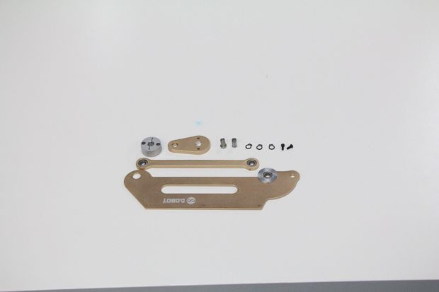

Step 8: Assemble the C axis with the small arm and small arm drive part

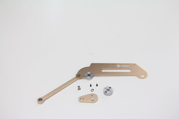
First, put two 1 mm washers between the C axis and the side of small arm with bearing bush. Second, put the φ6*12 axis through the hole and then fix it with two snaps.Third, put a 1 mm washer between the C axis and the small arm drive part and then put the φ6*12 axis through the hole and fix it with two snaps. After finishing these steps, we should fix the coupling with small arm drive part with by two M 2.5*10 screw. Now, we finish the main part of our Dobot arm.
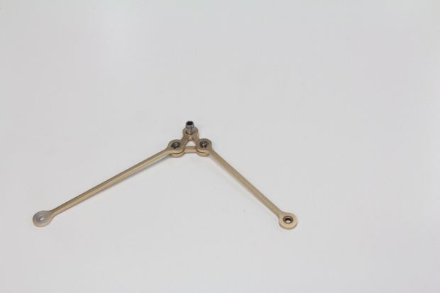
Step 9: Assemble the main arm with small arm and axes
This step might be a little bit complicated, so we should be careful when we assemble these parts.First, we use two M2.5 screws to fix the coupling with the main arm and ensure the coupling is on the left side of main arm.
Second, fix a snap on the φ6*42 axis and put it into the arm abduction decorative plates and then assemble it with the main arm.
Third, put two 0.7 mm washer to the axis and add the left small arm with the side of bearing bush to it.
Fourth, add the finished axes part in Step 6 to the φ6*42 axis and ensure the triangle linking part with a sleeve is connecting with the φ6*42 axis.
Fifth, add the small arm with C axis finished in Step 8 to the φ6*42 axis and ensure the sleeve is connecting with the axis and the small arm drive part with coupling is in the below and the add two 0.7 mm washers to the φ6*42 axis with the right small arm.
Sixth, fix the right main arm with the φ6*42 axis and then put the arm abduction decorative plates with the main arm and then tighten them with a snap.
Step 10: Finish the main part assembling
Now we put the four φ6*2 small circular block into the holes on the arm abduction decorative plates and then add some glue to fix it. After finishing that, we will assemble the arm head with the small arm. First, respectively put a 0.7mm washer in the left and right side of the arm head and then we put the φ6*30 axis. Finally, use two snaps to fix them and use some 32 copper pillars and M3*5 screws to fix the main arm and small arm and we all finish the job of assembling the main part of our Dobot arm.
Step 11: Build the base pad and the base motor

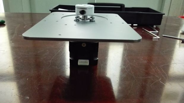
Fix the bearing pad ring and the base of Dobot arm with 4 M3 screws and then put the big thrust bearing on the pad. Assemble the motor pad with the DB-E02 step motor by 4 M4*6 screws and then fix the coupling with the step motor. Fix the step motor with the base pad with two screws. We must be careful with the coupling to ensure that we can tighten the motor stably so the lower end of the coupling is horizontal with the motor shaft chamfered edge.
Step 12: Build the right and left support
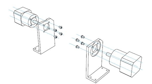
Now, let's respectively assemble right and left DB-E01 step motors with the coupling on the main arm and the small arm drive part and fix them with two M3 screws. We fix the motor support with the base part by 8 M4*8 screw. After doing these jobs above, we finally complete the mechanical part of Dobot arm.
A Dobot arm can do many things by changing the end effector. We might can build a writing and drawing Dobot and a laser cut and CNC Dobot and a 3D painting Dobot arm.If you want to know more details or have any questions, please free feel to contact us on Facebookor Official website:http://www.dobot.cc.
Step 14: Connect the circuit
After finishing the mechanical part of Dobot arm, we should connect the circuit of the Arduino control part.
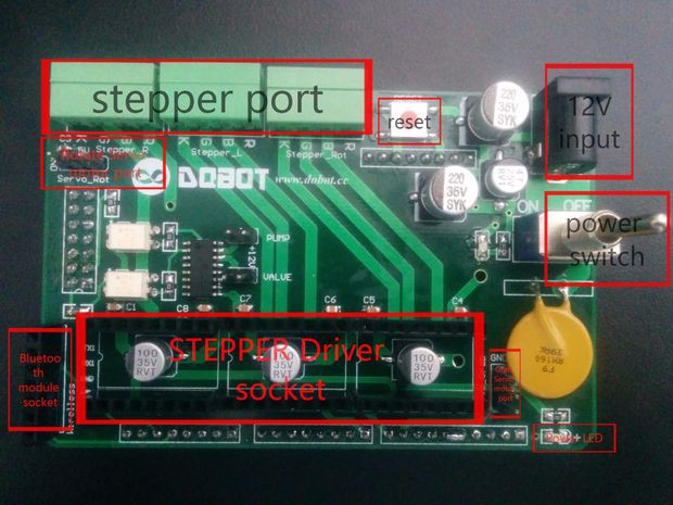
First, connect the Dobot shield to Arduino MEGA2560, as shown in Figure 1.
Second, insert the motor drive into the corresponding interfaces as shown in the picture above. After insertion, you will get something like in the picture below. Note the direction of the knob, do not insert reversely, otherwise it will burn after a power drive.
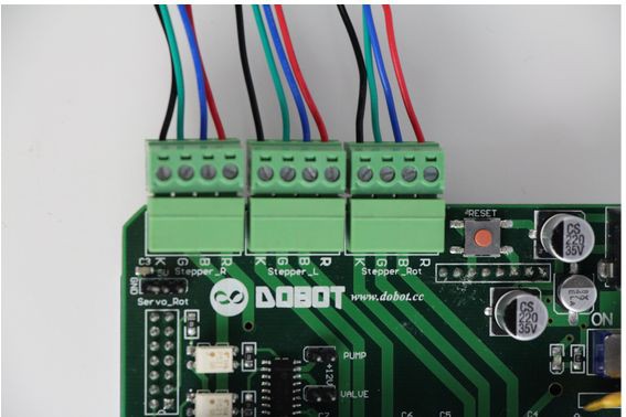
Third, insert the stepper motor terminals. “Steppter_R” terminal is for the big arm drive motor, “Stepper_L” connects to the small arm drive motor, and “Stepper_Rot” is for the rotation of the motor connected to the chassis. Board silkscreen "RBGK" means to be connected with with the motor "red, blue, green,black", respectively. Do NOT switch positions of the four lines as they have been pre-set in the factory.
Fourth, insert the 12V power adapter into the socket shown in Picture 1(c), be aware that you need to connect the power cord to the above shield terminal, instead of the Arduino MEGA2560 terminal.
Step 15: Assemble the laser cut head control with a relay or a 3D printing head and a bowden extruder.

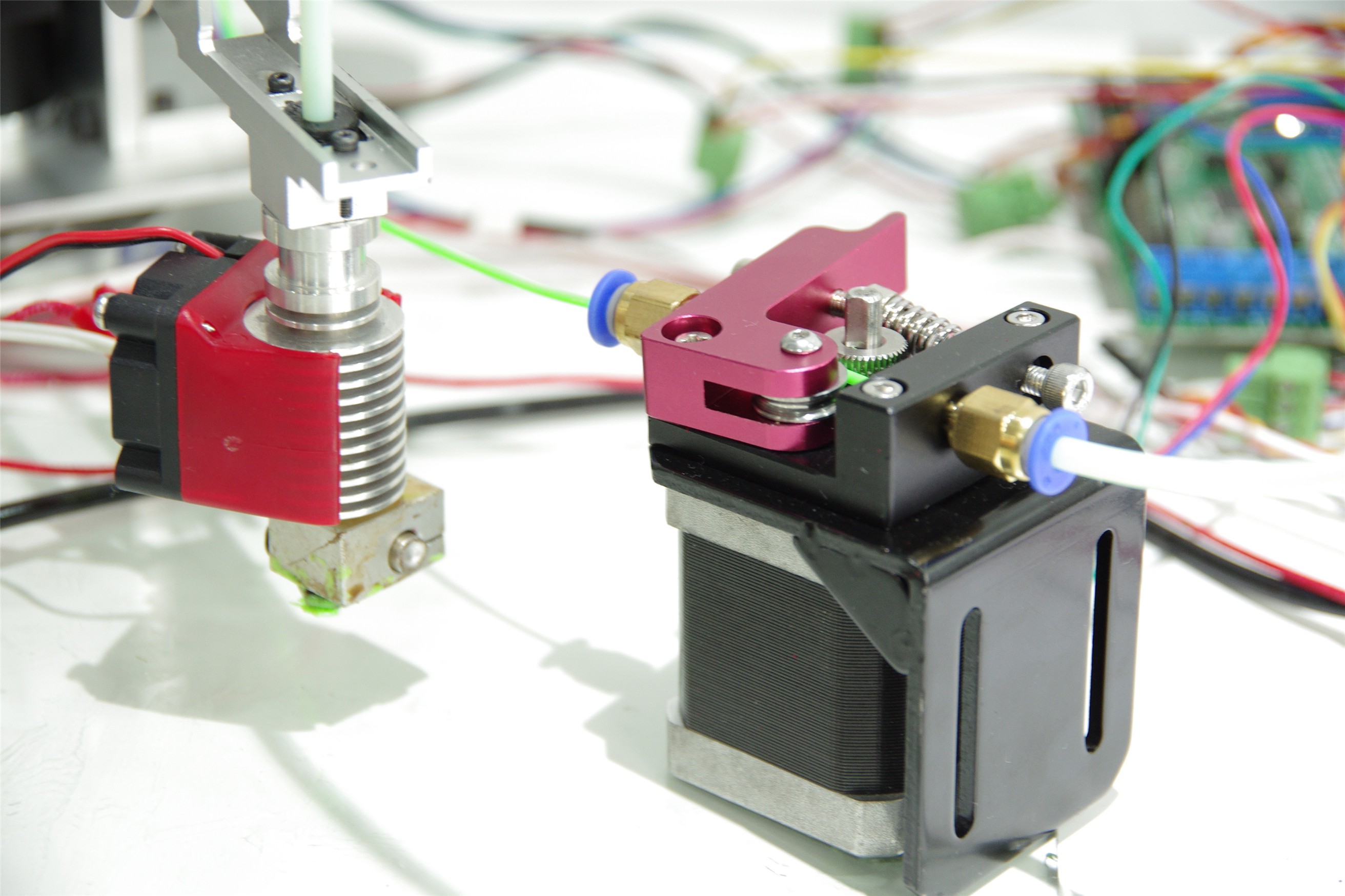
In this step, we use the 5V relay to control the power supply of the laser cut head.The first time we used the laser head 500mW found that cutting speed is too slow, then replaced by a laser head of 2W. The only difference between 500mW and 2W is the power supply need to change into 12V and the relay change as well. All the circuit is all the same as I show below.
What do you need:
a laser block, two M2*10 screws, two M2 screw nuts, an power adapter for laser head, 5V 2A power supply for laser head, a 5V relay, three female-head Dupont lines and a laser head.
What you need to do:
1, Assemble the laser head with the arm head: insert the laser head into the laser block, secure them with two M2*10 screws and two M2 screw nuts.
2.Connect the circuit: Connect the DC+ of relay with the 5V of shield. And connect DC- with the GND of shield. Then connect the IN of relay with the IO port of shield and connect these three lines with the Servo_Grab of shield by female Dupont line.
3. Connect the black line of laser head with the 5V power supply’s negative, and the red line of laser head with the power supply’s positive.
4.Connect the NO with the red line of laser head and connect the COM with the blue line.
Step 16: Finish the entire Dobot arm
Now we have finish the entire assemble process. Enjoy your Dobot robot arm! Now Dobot project is up on kickstarter, more applications have been developed and updated on campaign page, if you want to refresh the infos, please pay attention to the kickstarter updates. Thanks for your attention!