Overview
Please help support Project Ladon on Patreon!
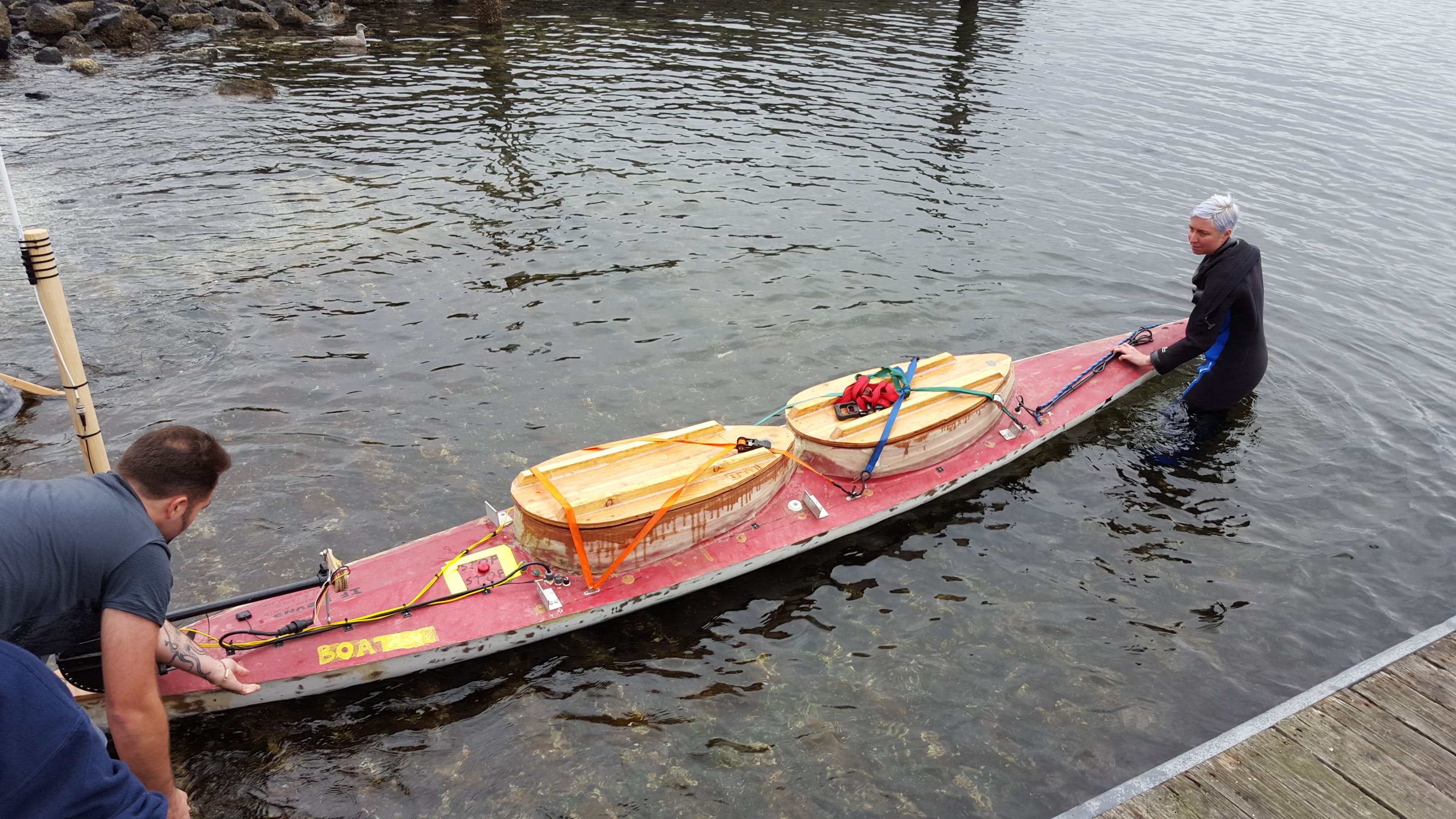
We're building an autonomous robot sail boat to circumnavigate the world. We have two boats -- a modified 18' two person kayak with solar-electric propulsion we call TSV Disputed Right of Way and a small sail demonstrator that doesn't really have a name yet.
Our current work is focused on refining our sail propulsion system and raising money to build the round the world boat. After we build that boat and send it on its way, we plan to offer our boats to researchers, fishery managers, and others who can use them to observe, protect, and preserve our oceans.
TSV Disputed Right of Way
This is the boat that let us get our feet wet. It's propelled by a small trolling motor powered by solar panels and a pair of truck batteries. It uses a single Beaglebone Black for brains, with an Adafruit 9-DoF IMU and Ultimate GPS for sensors. In the current version, it uses a MiFi for ship to shore communication and Adafruit.io for a control panel. It's taught us a lot about operating an autonomous boat on the water, but we've laid it up for now to concentrate on sail development.
Sail Demonstrator
We've developed a unique wing-sail rig we call a wing schooner for our sail demonstrator. It consists of a pair of self-tending wing-sails that can be controlled independently. Since they can be controlled independently, we can trim them to produce a turning force. That eliminates the need for a rudder, which means that we don't need to have any moving parts underwater.

A self-tending wing sail is not like the wing sails on America's Cup boats or the Vesta Sail Rocket. It's free to rotate around a vertical pivot and the direction it points relative to the wind is controlled by a small tail. This means that instead of the relatively large forces required to control an America's Cup wing sail, it only requires moving a small tail. The actuator for the tail is also far from the water.
Electronics
There are four main blocks to the sail demonstrator electronics:
- Main brain
- Ship to Shore
- Fore Sail
- Mizzen (Aft) Sail
The main brain is a Beaglebone Blue with an attached GPS, AIS receiver, R/C receiver, and battery. The Beaglebone Blue has, among other things, an onboard 9-DoF IMU and a battery charger. This drastically reduces the amount of support circuitry required and lets us pack everything into a Pelican 1040 mini case. This is still a work in progress, although most of what remains to be done with it is software.
Our ship to shore radio right now is a MiFi. Besides providing us coverage all over the Puget Sound, it also provides the access point for the onboard WiFi network. Using WiFi means that we don't need to have rotating electrical connectors for the sails. It also gives us a direct upgrade path for going offshore, because Iridium (among others) offer satellite transceivers that also can function as access points.
The foresail and the mizzen are identical with the exception of a program pin that determines whether or not the particular sail is fore or mizzen. They're built around the Arduino MKR1000, which provides both WiFi and a battery charger. There are also two sensors -- a Sparkfun 9-DoF stick and an angle of attack sensor. The 9-DoF allows the software to determine the angle between the boat and each sail by comparing compass headings. The angle of attack sensor tells the software which way the wind is blowing relative to the wing sail.
Unfortunately, there are no good, cheap, small electronic wind vanes on the market. We use a 3d printed vane with a magnet in it and a 3 axis magnetometer to sense the angle between the vane and the carrier. This gives us a direct read-out of angle between the vane and the wing, and therefore the angle of attack.
While we're developing the software to sail the boat, we've built a small manual controller out of another Arduino MKR1000 and a couple of pots. This provides straightforward (well, sort of) manual control.
Sail Demonstrator Hull
The hull of the sail demonstrator was designed to a) be the largest thing that could be cut in one piece on the laser cutter at Metrix:Create Space and b) be as easy to assemble as humanly possible. The hull is similar to what's sometimes called a Bolger Box (after the late Phil Bolger) -- plumb sides, plumb stem and stern. For extra ease, I went one better and made both the the deck and bottom dead flat and made the curve of the sides a simple arc. In order to make it even simpler, I used dowels for the stem and stern. I made the keel support and mast steps interlock with the bottom and deck in order to make the whole boat easy to assemble.
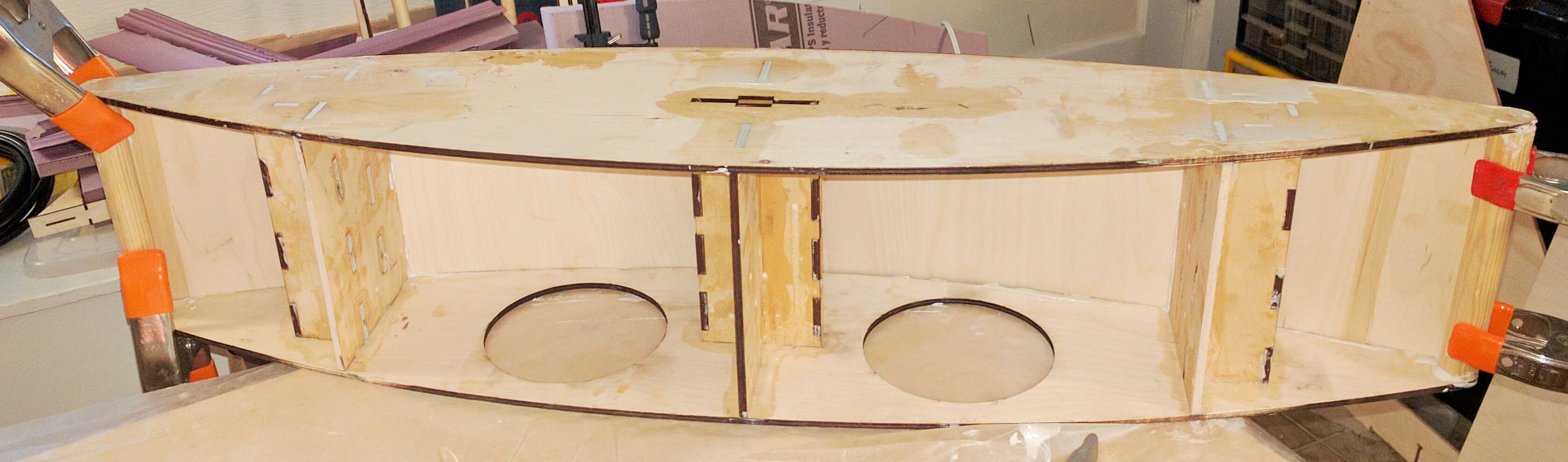
I didn't quite manage to get all the seams tight the first time, however -- when I did my first submersion test in my bathtub, I discovered a number of leaks which required more epoxy putty to seal up.
Wings
Building wings is a difficult proposition. Our first attempt used laser cut wood, wire cut foam, and was covered with heat shrink film. I learned that hot wire cutting is *MUCH* harder than it looks on Youtube and that extruded polystyrene and heat shrink film are not friends. I also made an error in control surface design that forced it to have a much larger counterweight than it would have otherwise; the required counterweight ended up larger than the design could accommodate so it was never going to work.
The current wing design, while heavy, can be balanced and responds to the control surface, which is a massive improvement, and means we can actually put the boat in the water and sail them around.
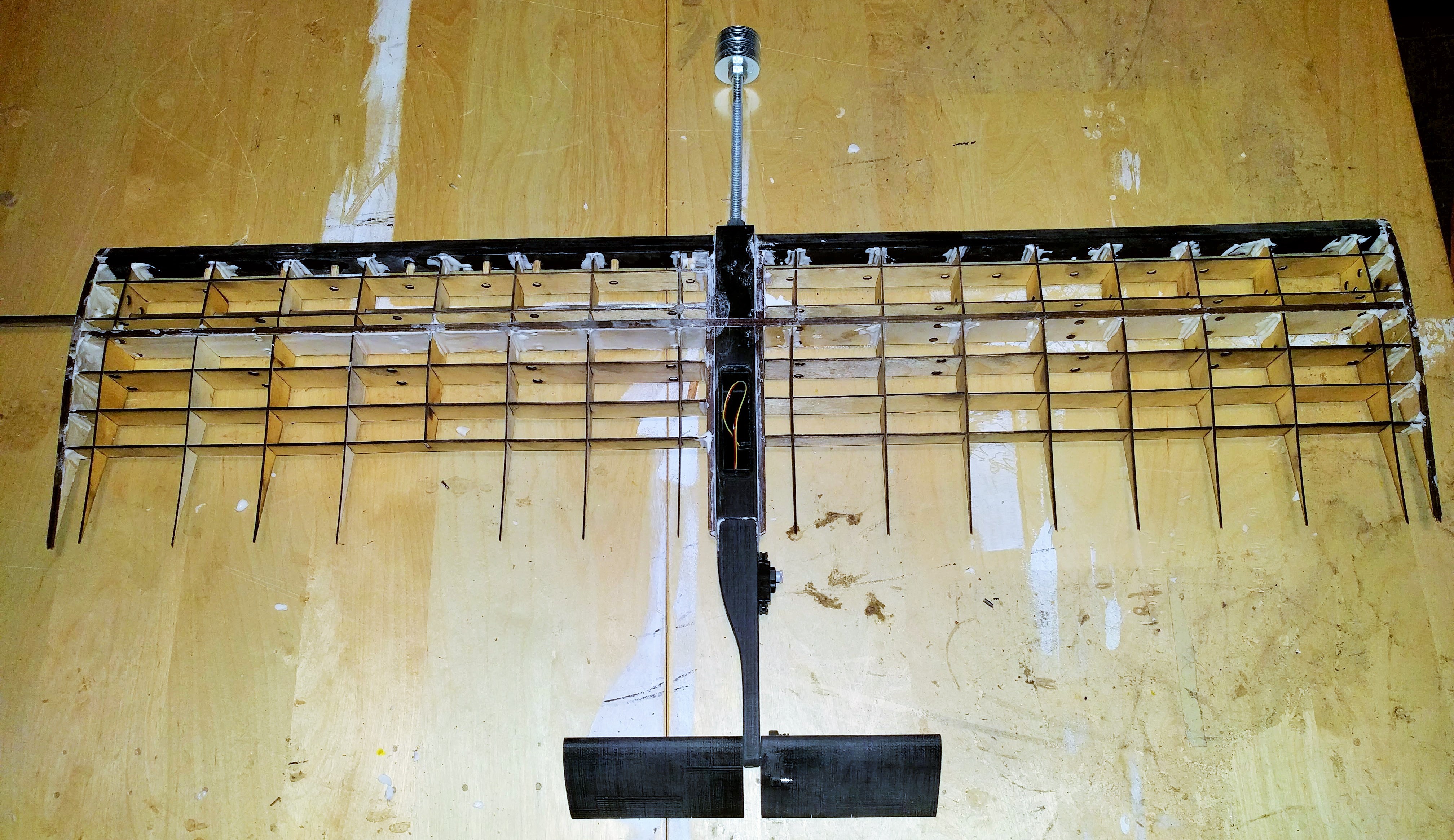
The tail boom, tail surfaces, counterweight mount, and leading edges are 3D printed from ABS. The reason the leading edges are included is because they have much sharper curvature than you can bend plywood around.
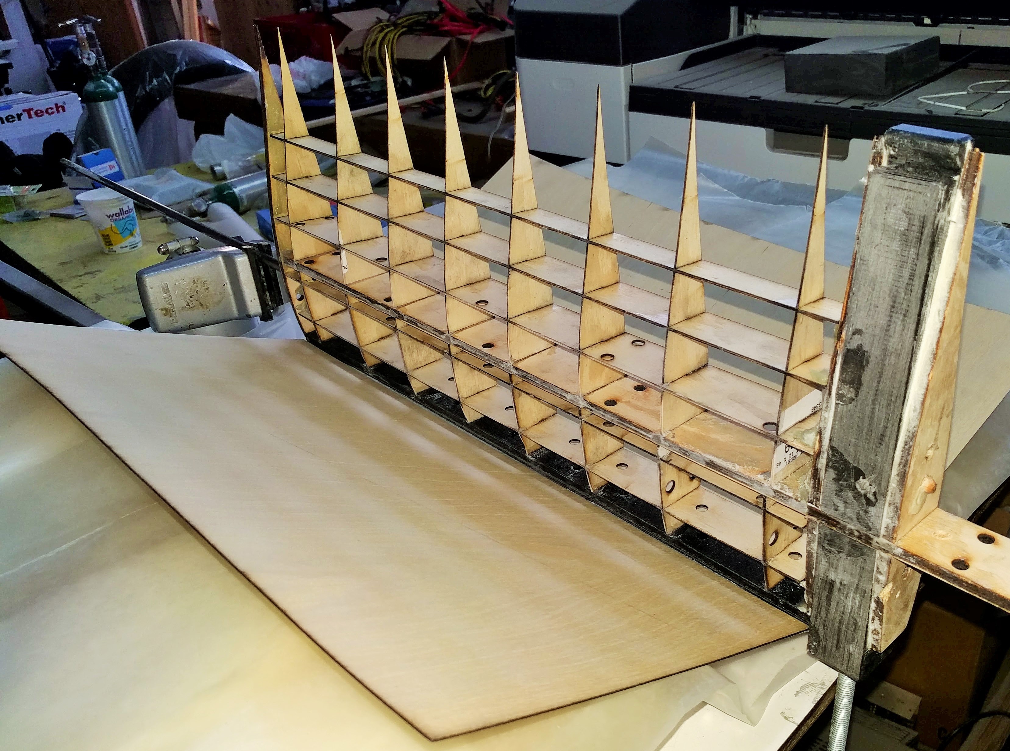
The main spar, the support structure for the wing skins, and the wing skins themselves are laser cut plywood. Autodesk's Slicer for Fusion 360 tool let me define the space where the ribs and most of the stringers went and it generated the patterns to cut them, which was a huge time saver in getting this wing design together. Here you can see the interior of one of the wings assembled before bonding the wing skins:
And ready for clamp up and glue:
The rod coming out the bottom drops into a pair of skate bearings installed in each mast step on the boat, allowing it to rotate freely.