 Evan
EvanPreface
The following content is pulled directly from the lab report that we wrote describing this project, so if you're having trouble understanding anything here please, please don't hesitate to send me a message and I would be more than happy to explain it on a less technical level!
I did not build this project alone! Much of the design, all of the motor circuit design, all of the Verilog, most of the cable work, and most of the CAD were done by my partner Kyle. I did the primary work on the LED control software and the control board design and population.
Overview
Persistence of vision (or POV) is the phenomenon by which the eye, seeing a rapidly moving objects, stitches together the object’s position at different times into a single cohesive image. This phenomenon is leveraged by CRT displays, which use raster scanning to draw individual pixels in each horizontal scanline before returning to the beginning of the next one. In contrast, our spherical display displays scanlines vertically. We have built a spherical display that creates a picture by rapidly alternating the colors displayed by each of a column of LED pixels. Each column of vertical pixels displays simultaneously. The physical location of the light source is then moved by a short distance before the subsequent vertical scanline is displayed.
Our system consisted of a 60-pixel LED strip mounted on an acrylic ring, which was lined with a 60-pixel LED strip running an array of LED pixels. Its bottom is mounted to a 6V DC motor with an encoder which uses a Hall-effect sensor to accurately determine its position. The motor’s rotational velocity is set to 500 rpm. A 6-wire slip ring from Adafruit allowed us to connect the LED power, clock, and data lines from a stationary frame to the rotating acrylic ring. (Since 6 wires are available, 2 wires each are used for power and ground lines.)
Our system's frame was constructed from scrap wood. The ring that carries the LEDs was 12" in diameter and laser cut from 1/4"-thick acrylic. 60 APA102 LEDs from Adafruit (strip density of 144 LEDs/m) were attached to the ring with CA glue. The top and bottom of the ring were both sandwiched between two 3D printed couplers, which contained a hole for the four LED wires (on the black encoder) and the motor shaft set screw (on the purple encoder).
The motor is mounted inside a square of scrap wood which is bolted to the bottom of the frame with four metal standoffs. The motor is glued into the wooden square. The bottom plank underneath the motor is drilled out so that the motor can be set deeper inside, but the motor itself cannot actually be snug inside the plank, as the fragile encoder on the bottom needs to be able to rotate freely. Additionally, the motor's 500 RPM rotation speed creates a lot of scary vibrations, so we added a little bit of damping on the top of the frame; hence, the brick weight seen in the pictures of the device in action.
- The Raspberry Pi sent 3.3V data out into a level shifter which sends 5V SCL and SDA lines into the LED strip. It also sends two lines into the FPGA: “Motor Toggle” and “Reset”. The +5V and GND input lines on the control board are spliced into a microUSB cable, which powers the Raspberry Pi.
- The FPGA receives the previously mentioned control lines from the Raspberry Pi. It also sends 3.3V from its regulator to the encoders on the DC motor. It polls both of the encoder lines from the motor.
- The motor is powered on the 12V rail. Its low side is driven by a power BJT, whose base is driven by the FPGA motor control pin. IMPORTANT: The motor is only rated for 6 volts, so the motor control Verilog is capped at a 75% duty cycle, or an equivalent input voltage of 9V. This is still an overvoltage, but a less severe one. Nonetheless, our power BJT on the motor's low side still grows extremely hot very quickly. A future design would revise this.
- The switch connects the PS_ON “green” rail on the computer power supply to ground, upon toggle. This provides a convenient on/off for the entire system, toggling the motor, LEDs, Raspberry Pi, and FPGA.
Here is a block diagram for the entire system.
All code for the project can be found here.
FPGA Motor Control (see motor_control.sv in the GitHub repo)
The purpose of the FPGA subsystem is to run the motor at a desired speed, with very little deviation from that speed. This is important because the Pi subsystem running the lights assumes a perfectly constant rotation rate. If the actual rotation rate is not the same as the assumed rotation rate, the image will drift around the globe.
The FPGA system creates a stable rotation rate by taking input from the motor encoder, running that data through a control loop, and then driving the motor with a PWM signal whose duty cycle is produced by the control loop. In hardware, each of these three tasks is done by a separate module. The high level block diagram of the system is included below:
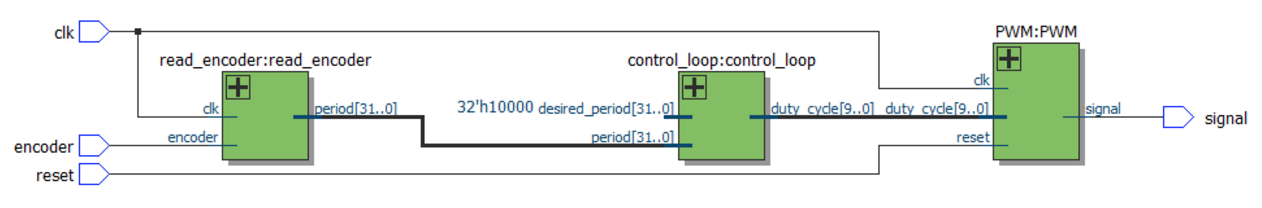
read_encoder
The read_encoder module is in charge of reading encoder data. The encoder puts out a square wave that has 12 cycles per revolution of the motor. The hardware module puts the encoder signal through a synchronizer so that all edges line up with clock edges. We implemented a 32-bit counter that resets on every edge of the synchronized encoder signal, and we output the value of the counter every time it resets. This gives us the period of the encoder wave, which represents one 24th of a revolution of the motor, in FPGA clock cycles.
control_loop
This module is the brains of the FPGA subsystem. The control loop takes period data from read_encoder and produces a duty cycle for the PWM module using a slightly modified PI control loop. A standard PI control loop outputs a linear combination of the error between the current and desired output and its integral. In our system, we ran into problems with the integral term while spinning up the ring. Because we are dealing with the period, we have a very large output value during while the ring spins up. It was so large that it was causing a huge overshoot in the integral term, which would then overflow. This caused the ring to spin up to full power, drop to a much slower speed, and then finally stabilize at the correct speed as the integral term overflowed.
We couldn’t just remove the integral term as we needed it to remove our steady state error. Instead, we decided to only allow the integral term to accumulate while the ring was spinning at close to the desired speed (more specifically, when the error in the period was within 4096 counts of zero). This allowed the ring to spin up using proportional control without accumulating and overflowing our integral term, and then to stabilize at the desired value using PI control.
The control loop module also runs on a slow clock. This is because the FPGA clock runs at 40MHz, but we only get new data from the encoder at about 1kHz when running at our desired speed. If we don’t slow down the clock, our integral term accumulates way too fast, and causes oscillations in the motors run speed as well as being prone to overflowing. We run our control loop clock at about 4kHz, which is slow enough to remove the danger of overflow but fast enough to reliably read data from the encoder.
PWM
The PWM module takes a duty cycle as an input and generates the corresponding PWM signal. This is a parameterized module, with variable duty cycle resolutions and clock divisions. The clock divisions argument is included so that we can set the PWM frequency. The module generates a slower clock, based on the divisions, to generate the PWM wave. To produce the PWM wave, we have a counter that is the same number of bits as the duty cycle. Once the duty cycle and counter match, we lower the output, and the output is raised every time the counter resets. This produces a square wave with the correct duty cycle at an arbitrary frequency.
LED Control (see yapg.c in the GitHub repo)
The APA102 chipset relies on 5V logic, so a 74ACHT125 quad logic-level shifter was used to pull the clock and data lines going from the Pi to the LED strip up to 5V from 3.3V. Also, a 1000µF capacitor is used across the LED power line, which smoothes out the extremely rapidly varying electrical load drawn by the LED strip.
The APA102 communicates via generic SPI. It supports blazingly fast data input; we are currently running it at 1 MHz. Each LED in the strip requires one 32-bit “frame” of data: three start bits, five brightness control bits, and 8 bits each of blue, green, and red color data. Once the APA102 device receives the 32-bit start frame 0x00000000, the device begins reading in the LED frames. Each LED has an integrated controller which reads its own color data and then clocks out the color data for the remainder of the string to the following LED.
The main C program initially enables the motor by strobing the “reset” FPGA pin (number 27) and then turning on the “motor enable” FPGA pin (number 22). It then enters the “hot loop”, which writes data out to the LEDs, until interrupted. A C signal handler is used to turn off the motor and all of the LEDs upon program interrupt.
In order to store the LED data, we need to create a data structure to hold enough LED data to display an image. In order to do this, we begin by defining a C struct for one pixel, which contains 1 unsigned char value for red, green, and blue. We then implement a 3D array in C, which stores the pixel values in a block of memory with the size (pixels in strip) * (columns of pixels in image) * (frames in animation). The getPixel() method returns a pointer to the pixel at a certain (x, y, z) position in the 3D array, where (x,y) describe its vertical and horizontal position in a displayed image and (z) describes the frame number of the pixel in question.
In the hot loop, the Pi writes data out via SPI to the LED pins, then sleeps for one “delay period” in between incrementing the values of the vertical LEDs to display. The “delay period”, in microseconds, is calculated by the following formula:
Delay = (1000000 * 60) / (columns of pixels * RPM)
Once we reach the last column of pixels, we reset to the first one. If we have multiple frames in our pixel animation, we revert to the first column of the subsequent animation frame. Our timing is perfect if this reset happens exactly once per revolution.
A number of considerations were put in place in order to time the LED frame changes properly. First, rather than using the delayMicros() method built into the provided easyPIO.h method, we write a custom method that returns the value in the Raspberry Pi’s timer register. At the beginning of our hot loop, we poll the SPI timer register. At the end (after the SPI data has been written out) we check to see if the desired amount of time has already elapsed. We do not repeat the loop until the timer register indicates that the desired amount of time has passed. This is superior to the delayMicros() method because it reduces delay by taking into account the amount of time required to send data over SPI.
Finally, in the step immediately before pixel data is sent to the LEDs, a simple gamma correction function is applied, mapping each color value cubically to increase color contrast and accuracy.
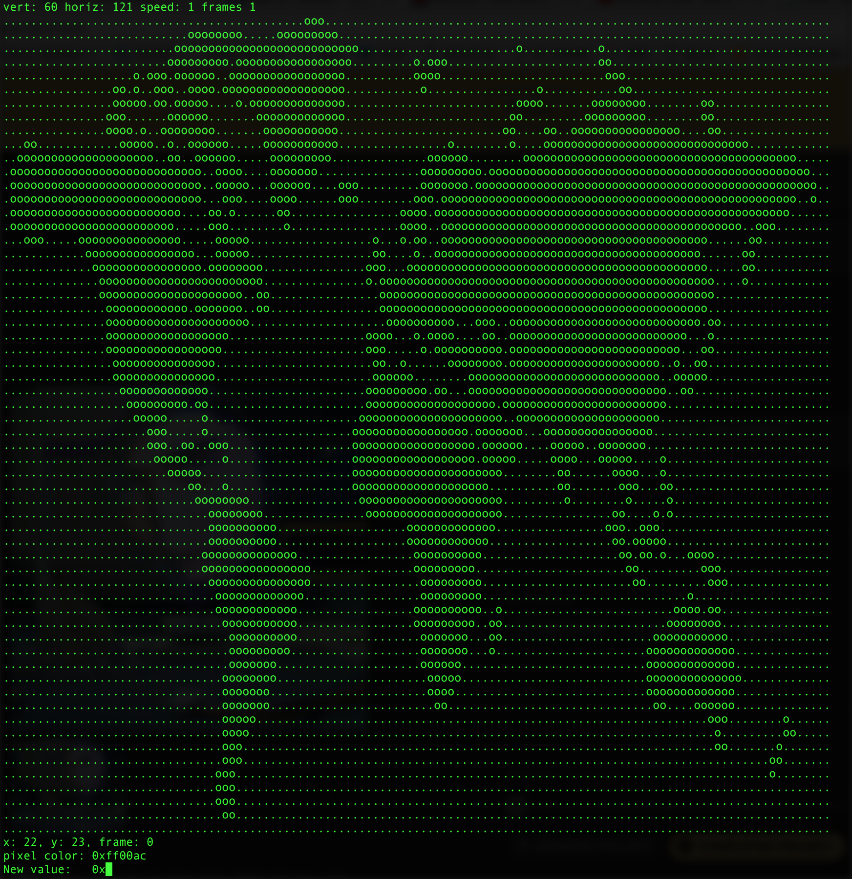
Editor (see write_file.c in the GitHub repo)
In order to change the content that we write out to the sphere, we need a program that can save the content to a file. Therefore, we define a .led file format as having the following characteristics.
- 4-byte header, composed of the following values:
- First byte: number of vertical pixels in one column. (x)
- Second byte: number of horizontal pixels in the image. (y)
- Third byte: number of frames to hold one animation before moving to the next one.
- Fourth byte: number of frames in the animation. (z)
- 4 empty bytes (in case future file formats want to store extra stuff in the header)
- LED data stored in a generic 3D C array - z frames of y columns of 3*x bytes
Reading or writing a .led file with the editor (write_file.c) initializes these four constants and allocates memory for the LED data according to their values. Opening a .led file with this editor also allows the user to accomplish the following functions, necessary to create an animated or still image:
- Move cursor through LED matrix and between frames of animation; manually set color values
- Increment red, green, blue channels of individual pixels
- Copy and paste pixel color values onto other pixels
- Clear pixels
- Shift entire image up / down / left / right
- Copy and paste entire frames
- Save onion-skin mode (previous frame is overlaid on top of current frame).
- Write out to .led file.
The file editor is implemented in ncurses, a common framework for building graphical command-line applications.
Converting Images (see imgprocess.py in the GitHub repo)
The Python library PIL was used to convert images from any standard file format into pixel globe-compatible color data arrays. A simple loop, consisting of just over 20 lines of code, loops through every row and column of pixels in an input image and outputs the color values as “unsigned character” values, then writes them (prepended with the appropriate 4-byte header file, as described on the previous page) out to a .led file whose name is specified by the user.
Some pre-processing is required to make sure that the image converter does its job properly. The picture to draw must be rendered down to 60 pixels high in order to ensure that it displays on the proper number of LEDs. Also, experimentally we can determine that at 500 rpm, an image with a width of approximately 130 pixels will result in pixels on the globe appearing to have an equal width and height. Aesthetically, increasing the contrast in an image is also helpful.