 Bradley Worley
A quick and dirty introduction to the PyPPM
Here are a couple short summaries of the "what" and "why" behind my PyPPM project.
Still interested? Awesome! Read on, friend...
How an Earth's Field NMR (EFNMR) experiment works
The first-revision PyPPM operates using the Varian-Packard method, named after the two inventors. (For information on the second-revision operating scheme, keep reading further down in the details)
Using the Varian-Packard method, an EFNMR experiment can be boiled down into three stages: polarization, quenching, and acquisition...
- Polarization: During this first stage, the sensor coil is connected (via a relay) to a constant current sink that maintains a current of roughly 2 Amps. The sample in the sensor coil develops a magnetic polarization that increases exponentially in time, with a time constant of a few seconds (T1). This stage usually lasts about five to ten seconds, depending on the amount of polarization required to achieve the desired signal amplitude.
- Quenching: This is the most critical step for a Varian-Packard design. The current sink is switched off, and the energy stored in the coil (and thus it's magnetic field) must be rapidly quenched. If the field is not quenched rapidly enough, the sample will not keep it's magnetic polarization, and there will be no signal. (More on this later)
- Acquisition: If everything went as planned up to this point, the sensor coil is connected (via the same relay) to an analog signal chain that provides 110 dB of amplification over a 3 kHz bandwidth centered around 2 kHz. The amplified signal is digitized and sent via USB to the host computer for further processing.
The entire scheme is shown graphically below.

And a few final notes...
Polarization dead-times: The astute reader will notice that there is a short dead-time between relay switching and turn-on/turn-off of the current sink. This allows the fragile relay contacts to move between positions without having to worry about arcing due to unquenched inductor current.
Acquisition dead-time: A second dead-time is placed after the polarization stage of the experiment to give the relay contacts even more time to stop chattering before the low-voltage signal is acquired through the analog signal chain.
Recycle delay: This is a feature to satisfy the chemist in me. If multiple scans (polarize, quench, acquire) are performed in order to increase the signal-to-noise ratio of the final signal, the device is should wait a bit between scans, both to let the coil cool and to allow the sample to return to its equilibrium state.
PyPPM Hardware system-level overview (a.k.a. first revision System Design Doc)

Sensor coil: The sensor coil is arguably the most critical component of an EFNMR system. It's inductance and resistance determine how fast it can be switched on and off, how much current it can carry, and how sensitively it can detect the weak oscillating magnetic field produced by the sample.
The current sensor coil design (rev 1.0) in the PyPPM is a 10.2 cm long solenoid wound around a 5.0 cm diameter PVC pipe. The solenoid has four layers of 158 turns each, totaling to 632 turns of AWG 22 enameled copper wire. The solenoid has an approximate inductance of 7.5 mH and a resistance of 5.5 Ohms.
Future versions of the sensor coil will focus on providing a level of humbucking to minimize the amount of electrical interference that is received during acquisition. The current coil easily detects the 30th harmonic of 60 Hz mains wiring from hundreds of feet!
Sensor relay: The relay switches the sensor coil between the polarization circuit and the acquisition circuit. A small-signal DPDT relay (Omron G6A) was chosen to ensure galvanic isolation between the low-noise analog signal chain and the noisy polarization circuitry.
Polarization battery: The current design of the PyPPM admits any DC voltage source under 15 V, battery or otherwise. However, this voltage source must be able to maintain several Amps of current for several seconds. A lead-acid car battery is currently being used with the PyPPM, which allows the system to be used away from mains electrical systems.
Constant current sink: The constant current sink must be capable of switching several Amps through an inductor. The current design uses a logic-level MOSFET to close the circuit between the sensor coil and ground. A gate driver is used to ensure the MOSFET is turned off hard.
While turn-on may be slow (based on the L/R curve), turn-off must be rapid (less than 500 microseconds). Given the parameters of the sensor coil, the current sink has to rapidly absorb 20 mJ of stored inductor energy during quenching. This is accomplished by paralleling a TVS diode with the MOSFET.
Analog signal chain: The voltage induced through the sensor coil is tiny - a couple hundred microvolts at best. The role of the analog signal chain is to boost this signal out of the noise floor (coil RMS thermal noise is ca. 18 nV) to a level that is suitable for digitization on a 5 V full-scale.
- Instrumentation amplifier: The INA stage (based on the Analog Devices AD8428) provides a flat 66 dB of gain from DC to 15 kHz with high CMRR and PSRR.

- Low-noise gain stage: The signal from the instrumentation amplifier is capacitively coupled into an Analog Devices AD8597 in a non-inverting configuration, yielding an extra 40 dB of gain and an extra high-pass cutoff at 16 Hz.
- Band-pass filter: The BPF stage (based on an Analog Devices OP462) provides an 8th order Chebyshev response with a bandwidth of 3.7 kHz, a band center of 1.4 kHz, and pass-band ripple less than +/- 0.5 dB.

- Analog-to-digital converter: The signal from the band-pass filter stage is capacitively coupled into a resistive voltage divider that centers the signal at 2.5V. The resulting signal is buffered into an Analog Devices AD7680 16-bit SAR ADC, which can comfortably run up to 100 kS/s, but seldom ever runs faster than 20 kS/s in the PyPPM.
Analog power supply: An early design requirement for the PyPPM was to keep everything powered by the USB 2.0 bus, with the exception of the polarization power supply. To accomplish this, the analog power supply converts the noise-laden 5 V USB rail voltage into +/- 5 V rails, capable of supplying tens of milliamps with around 100 microvolts of noise and ripple.
Microcontroller: An Atmel ATmega32U2/4 8-bit microcontroller is used in the PyPPM to coordinate experimental timings, read data from the ADC, and interface to the host computer via USB 2.0. The PyPPM registers as a USB 2.0 CDC-ACM (USB-serial device), which shows up as a character device node in Linux and Mac OS X.
Host computer: The software written for PyPPM requires Linux or Mac OS X in order to work. Work is underway to interface the PyPPM to a Raspberry Pi running Apache (PiPyPPM anyone?)
PyPPM second-revision System Design Document
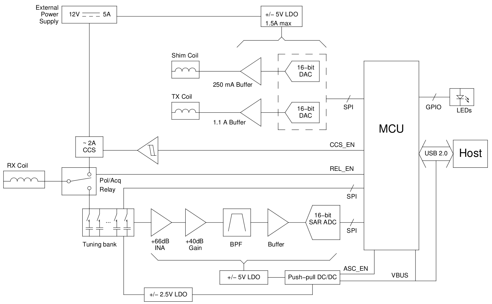
The second-revision PyPPM hardware design incorporates a significant number of new features that will facilitate use in environments that are less hospitable to EFNMR (inhomogeneity, interference). Here's a rundown of everything new:
- Capacitive frequency tuning: Removal of interference is most effective at the source: the sensor coil. By placing a capacitance in parallel with the highly inductive sensor coil, a tank circuit may be created to accept a narrow band of desired frequencies and reject other interfering signals. The PyPPM v2 hardware includes a "16-bit" digitally controlled capacitive tuning bank for just this purpose.
- Single-axis field shimming: Using the PyPPM indoors requires at least some ability to correct for magnetic field inhomogeneity around the sensor coil. A DAC-controlled shim coil driver on the PyPPM v2 hardware allows for first-order correct of field inhomogeneity along a single axis, given the proper shim coil geometry.
- Adiabatic ("soft") pulsing: The Varian-Packard method described above works well to simply measure magnetic field strength, but it cannot ask more detailed questions of the sample. The PyPPM v2 hardware is capable of Direct Digital Synthesis of sinusoidal pulses and adiabatic polarization, opening up a much greater array of possible experiments to the user.
- Pulse programming: A flexible mini-language has been developed that allows PyPPM devices to run any desired sequence of instructions (e.g. acquire data, soft pulse, re-tune, etc). To write a 'pulse program', the user simply has to write a list in Python that conforms to a well-documented (yet in-flux) syntax.
PyPPM Software overview
The software written to communicate with the PyPPM hardware can be split into four categories: the core C library, the command-line tools, the graphical tool, and the Python extension.
- Core C library: The core library provides functions that read and write to the character device created by the operating system for the PyPPM hardware. Core functions are implemented for reading and writing experimental parameters to the device, as well as running experiments and resetting the device. All communication with the device is managed by blocking operations, so nothing else can happen in the thread while talking to the PyPPM
- Command-line tools: The command-line tools are essentially wrappers around the core library functions, and are mostly useful for debugging the hardware.
- Python extension: The Python extensions are what give the PyPPM it's name! Using these extensions, the PyPPM may be connected into any Python program imaginable, including an Apache server-side script. One goal of this project is to host a PyPPM device on the web, allowing users to connect to the device and acquire a Free Induction Decay signal with a click.