 Ryan Bailey
Tiny Wireless Capsule Camera
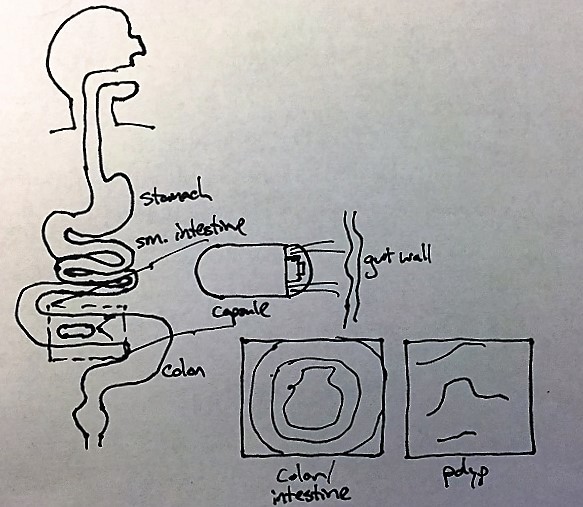
A capsule endoscope, also known as a capsule camera, is a tiny camera that can be safely swallowed and passed through the digestive tract. The device uses one or more camera sensors to capture images of the gastrointestinal tract and is useful in diagnosing or evaluating a myriad of diseases or dysfunctions of the digestive system. Many configurations are possible, but the core functions boil down to (1) capture images, (2) process and either store/transmit the image, and (3) operate continuously for 24-48 hours.
This kind of device is especially convenient for evaluating hard-to-reach places (such as the distal small intestine). It is also useful in situations where the patient cannot (or refuses to) tolerate more conventional approaches such as colonoscopy or esophagogastroduodenoscopy (EGD a.k.a. upper GI endoscopy). Though capsule cameras have not supplanted these conventional, "Gold-Standard" methods, they nevertheless have become an invaluable medical tool.
Why do this project?
Short version: I think it would be fun to build one.
Long version: Around the hospital, I have occasionally had the privilege of seeing these devices in action. The branded, FDA-approved versions used in real human patients are incredibly sophisticated systems with years of research and safety testing behind them. Like most things in medicine, they are also incredibly expensive and, understandably, highly proprietary. Devices like these take millions of dollars to develop and years (even decades) of research and development before they even see human trials, let alone actual sales. Overall, it's pretty inaccessible technology.
Still, the proliferation of tiny, versatile cameras in phones, tablets, and elsewhere made me wonder if it would be possible to develop a capsule camera with off-the-shelf parts and open software, and build it with materials, manufacturing, and resources readily available to the amateur hacker.
Crazy? A mini 2MP camera module in a 8mm x 8mm package can be bought on eBay for <$5. Incredibly powerful 32-bit micros have become completely accessible to total novices. A 4-layer board with 5mil pitch can be had for $10 per square inch (of note, I estimate the total board area needed for this project to be barely 1 sq inch. Even relatively cheap 3D printers may be able to make a suitable enclosure. This is hardly crazy (ok, maybe a little).
Application Example:
Full disclosure: I do not at this time have plans to ultimately test this device on living (human or otherwise) subjects. That particular ethical and legal minefield is not something to shoot for at this time.
Top-Level requirements
The system I want to build must meet a handful of high-level requirements.
- Single camera VGA or better resolution (2MP goal) imaging captured at least every 10 seconds
- On-board storage of at least 15 minutes of images
- Wireless transmission of image data to external storage device
- 24-hour battery life
- 15mm diameter x 30mm length maximum (smaller better)
System Design
Overall System
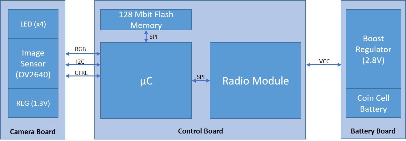
The capsule hardware consists of three separate boards/modules:
Camera: contains the image sensor, LED flash, and supplemental power regulation required by the image sensor.
Battery: contains the battery holder, magnetic reed switch for power on/off, and the main boost regulator.
Control: contains the processor, storage memory, and radio transceiver.
Camera
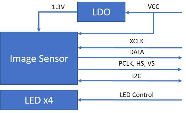
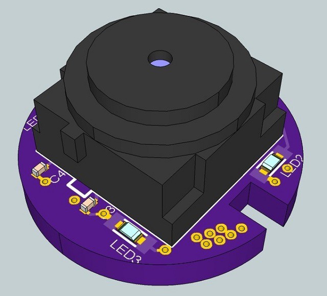
The camera board contains the OV2640 camera module, a (up to) 2.0 megapixel image sensor with parallel RGB outputs. The image sensor requires a 2.8V rail for digital and logic, and a 1.3V rail for analog power (provided by a small LDO regulator). Since the typical application lacks ambient light, there are 4 white LEDs to provide a 'flash'.
The OV2640 accepts a minimum pixel clock of 6MHz (nominal 24MHz), provided by the system processor. The camera data electrical interface is 8-bit parallel, configurable as YUV, RGB, or RAW. The datasheet also mentions JPEG compression as an option, though this does not seem well-documented.
Power
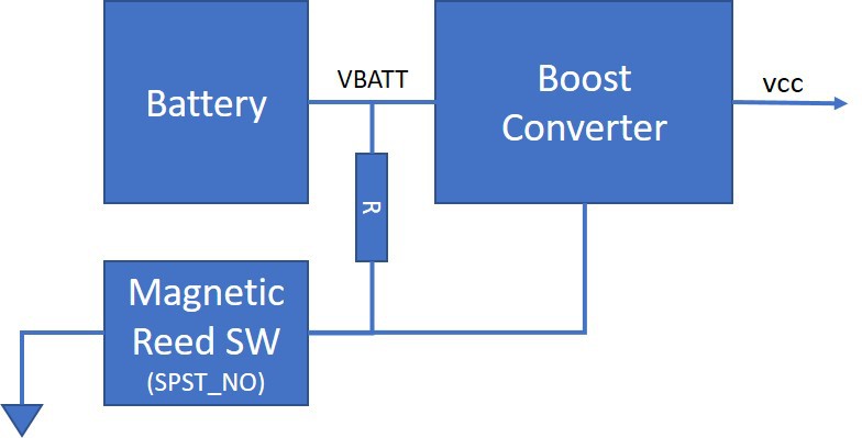
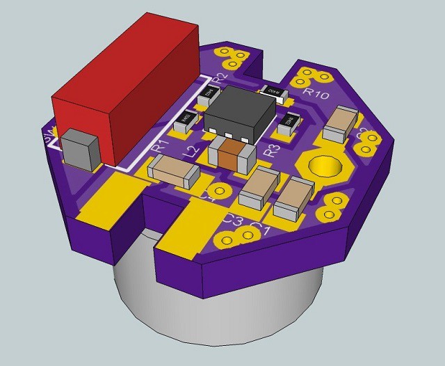
The entire system is powered from a single 1.55V 75mAH silver-oxide button cell battery. This is housed via a small retention clip on the power board. The power board also contains a boost regulator to convert the input voltage (1.55V nominal, ~0.9V minimum) to 2.8V. Since the camera requires a 2.8V main supply, all other ICs in the system will run at 2.8V.
Turning the system on/off is a slightly confounding challenge given that the system will be sealed in a plastic capsule. A small magnetic reed switch (SPST-NO) will control the enable pin of the boost regulator, putting the system into a power-down state when a small magnet is placed near the device. This is similar to how some cardiac pacemakers are controlled.
Main
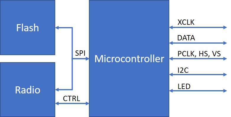

The main board runs along the axis of the device and houses the processor, image storage memory, and the radio transceiver. It also bridges power from the battery module to the camera module.
The processor implements the 8-bit parallel video interface to the camera, including data, sync, and pixel clock. It also provides a 6-24MHz reference clock used by the image sensor. It also implements flash control, I2C interface to the camera, and control interfaces to the memory and radio transceiver.
Enclosure/Mechanical
The electronics will be enclosed in a sealed capsule. Most of the capsule will likely be 3D printed in a bio-compatible material and may also be potted to some extent. The end housing the camera will be covered by a clear cap.
License
Schematics, PCB design files, and manufacturing documentation are released under the CERN OHL