Joel Villa Farias
How was the CierzScience Tunnel project born
The idea of this tunnel came to not having neither project nor tutor of thesis at the end of my career as aeronautical engineer. After having tried to develop a project proposed by a professor at the University and know that he was far above my knowledge , I decided to be I who chose the project and as I develop it.
My first idea was to build something physical related to my career and that it could be used in the future and not to be forgotten and useless, in the act I thought to build a wind tunnel.
After a brief search on the Internet I had an idea of how it would be my tunnel, but I note that, although there were many projects like that I wanted to make, there was nobody who had detailed step-by-step how to build a wind tunnel. In one they give you an idea of how to make the body or an idea of how to develop the electronic or the measurement of forces, but none so complete.
So I decided that my project was to build the most complete possible wind tunnel, and then be able to share it with the community. Even if the result will not be perfect and that it should be go refined, I hope that will serve as a basis or guide to someone who want to repeat it enter the changes that it seems that enhance the design.
At the same time I thought in the design I thought also in the name of the project. My city, Zaragoza, is characterized by a strong wind called cierzo and I wanted to make it a tribute and end up calling the project: CierzScience Tunnel .
How to design our own wind tunnel
To design our own wind tunnel, the first thing that we need to assess is the complexity that we want to give to the project that will have an impact on the quality of the results of the tests that we make in him. Second, the maximum size of the objects that we want to study that will have an impact on the size of the testing chamber and therefore in the rest of the tunnel. Third the speed of the air that we want to reach in the test chamber.
There are basically two types of wind tunnel depending on the air circulation in its interior, closed or open. With the first we have conditions thermodynamic stable and the study would be more precise but will be of a building more complex and take a larger space. With the second we will not have conditions thermodynamic as stable although the complexity of its construction and the space that deal will be lower. In this case we decided the second configuration. With regard to the other types of configurations we chose testing chamber closed, air aspirated and of course subsonic.
Our tunnel is thought, in the beginning, like a basically didactic tool that should allow us to visualize the flow lines about a body and to measure on him the forces to which it is submitted. The size that we think that it would be the correct one would be one that was occupying a volume of about 15 cubic cm. Later these bodies can be extrapolated to others of major size.
To carry out the design we have to predefine a speed of the air inside the test chamber that would allow us to carry out the studies. The speed of 70 km/h would be a speed that would allow us to realize them. To perform the calculations take the speed of 20 m/s.
In the case of the construction of the CierzScience Tunnel the first thing that we acquired was the fan of second hand that conformed to the features that we were looking for. The air flow that moved, its size, the structure on which was mounted and the price were the ideals for our project.
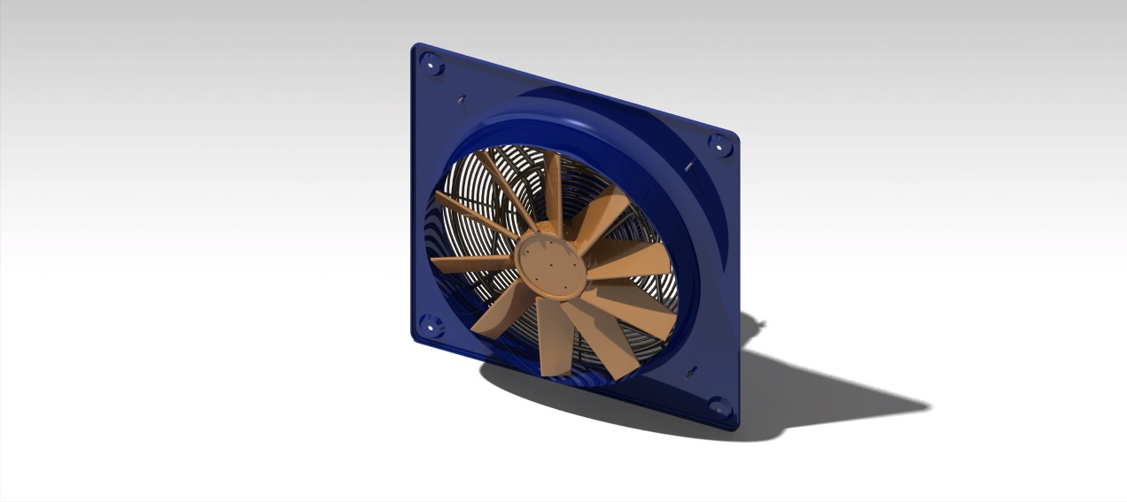
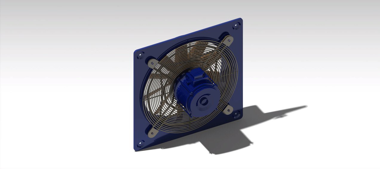
From the diameter of the structure of the air output of the blower, the flow rate that offers us the fan, the speed in the test chamber and the volume of the object of study, we will design the rest of the tunnel.
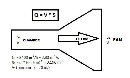
The flow that offers the fan is 8400 m3/h, 2.33 m3/s. Its section we estimate from the radio. Being the radius 0.25 m, the area of its section is of 0.196 m2.
Knowing that the flow is the result of the product of the speed and the section:
Q = S(2)*V(2) ; V(2) = Q/S(2) = 2,33/0,196 = 11,88 m/s
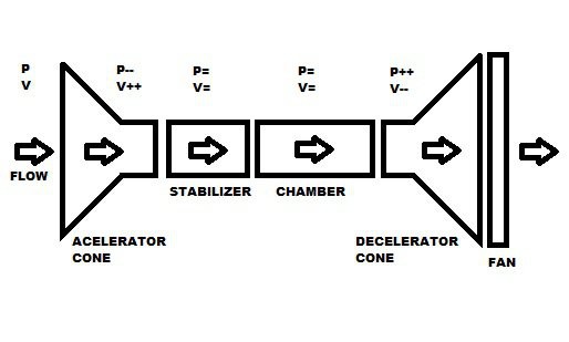
Now, we know that the flow rate through the fan has a maximum speed of 11,88 m/s. Knowing that the flow rate is maintained along the whole tunnel, because it is a clear example of the Venturi effect, we can calculate the area that the camera section must have to comply with the requirement that, by the camera, the flow has to achieve at least a speed of 20 m/s.
S(1) = Q/V(1) = 2,33 / 20 = 0,1165 m2
Knowing the area which must have the section decide the geometry of the section that it will comply with such an area. By issues constructive and taking into note that you must include the balance and other instruments in the Chamber, we decided that the section must be square. Being the area 0,1165 M2, the section is calculated as the square root of that is 0.34 m. For reasons constructive we mark the square section of 35 cm, it reduces the maximum speed that can be attained in the chamber to 19 m/s but we accept this small difference.
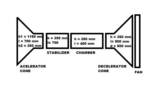
Once calculated the dimensions of the camera, and knowing the fan, automatically we have that the diffuser will have at one end a section of 35 cm side and on the other end of a circular cross section of 50 cm in diameter. The length of the diffuser is obtained later.
As in the case of the diffuser, the stabilizer will also be marked by the section of the camera. The stabilizer will be constant section, thus the opposite end to the camera also enjoyed the same section. The long be obtained later.
It only remains to define the geometry of the cone of acceleration. Analyzing other tunnels already constructed there are three types of geometry that could have the cone of acceleration of our tunnel.
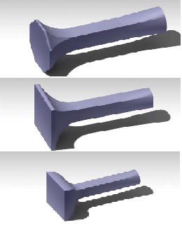
Constructively first, the section octagonal, is the least problems would give. The angles of the geometry of the structure are less closed that the other. It is less complicated turning out this geometry and the final structure would be more solid.
Finally we apply all sections and geometries of the design studio in the program of Catia. With this program we will by varying the lengths and the measures of the cone of acceleration to obtain the final result. We have to design it taking into account that from one section to another the transformation is as soft as possible so that the flow is as more laminar as possible. This design have achieved the following results.
How to verify our wind tunnel design
Once we have our design of wind tunnel made with Catia, we analyze the design to verify that the flow is laminar, there is the less turbulence possible and the speed in the test chamber is desired. To check the design we export the file of Catia to Abaqus and follow the steps that are shown in the following video.
HOW TO DESIGN OUR TESTING CHAMBER AND THE BALANCE
In the design of the test chamber section will be given by the section that we determined for the stabilizer section and the diffuser inlet and the length we determined that it would be of 400 mm.
The testing chamber we cannot build as the rest of the body of the tunnel, because we need a transparent material in order to visualize directly the flow of air around the object of study with the help of the smoke creed by the smoke machine. The material that we will use will be the methacrylate subject by a structure angles of aluminum.
The camera will have to have a side that can be removed easily, by unscrewing, in order to be able to manipulate the inside of the camera without having to separate it from the rest of the body.
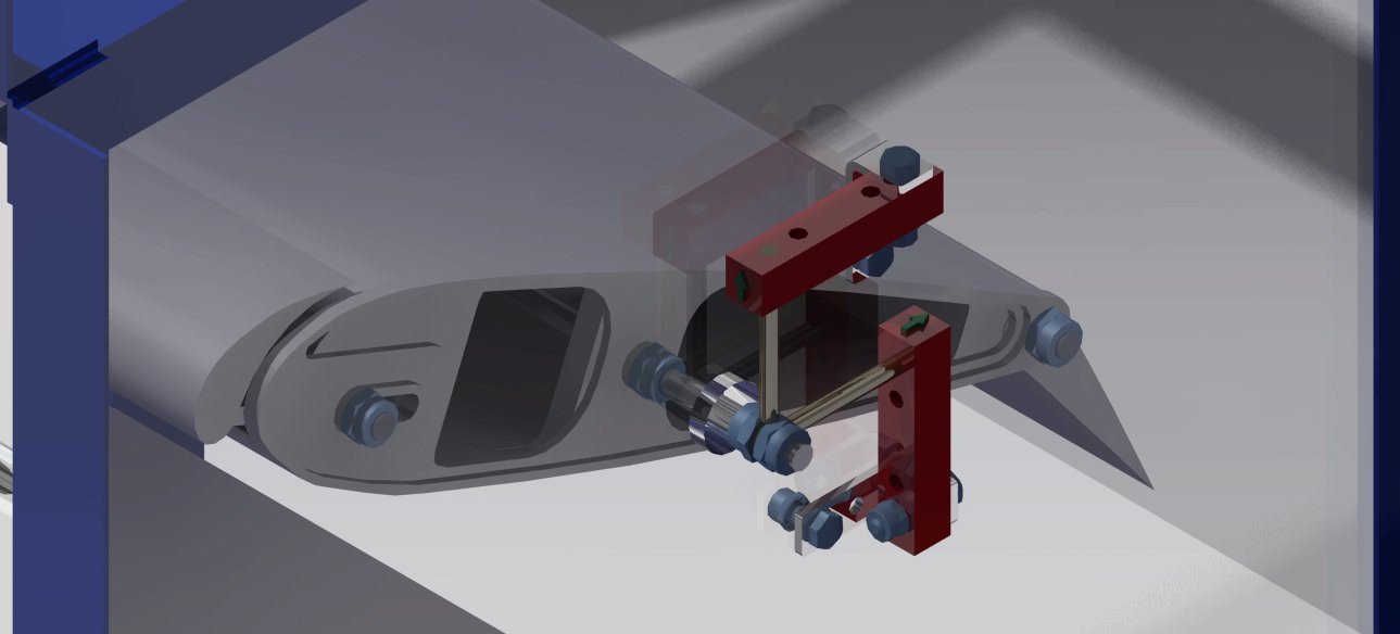
Under the camera is put the system of the balance that will measure the forces that are exerted on the object of study. This object anger located on a support that will transmit the forces the system of the balance. The system of the balance we have designed from a schema that provides the web page of the NASA. The schematic shows a structure that have incorporated strain gauges located within a certain distance of the object. This balance will allow calculate the lateral forces, the lift, the drag and the moments of rolling, yawing and pitching.
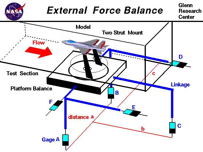
To calculate the forces and moments we will continue the following equations that have by variables The force measured by the sensors and the distances between the sensors and the object.
The lift (L) is given by:
L = A + B + C - W
The drag (Dr) is given by:
Dr = E + D
The side force Y is:
Y = F
If there is no rolling moment, the values of A and B are equal. If there is a rolling moment (RM), the value is equal to:
RM = (A - B) * a / 2
Similarly, the yawing moment, (YM) is equal to
YM = (D - E) * c / 2
and the pitching moment, (PM) is equal to
PM = C * b
The structure that will envelop this system of sensors and will serve as a static end of the system will be built with the same philosophy as when it has been built the camera.
HOW TO DESIGN THE STRUCTURE TO HOLD THE FULL TUNNEL BODY
Now when we have the whole body of the tunnel, including the camera of essays and the fan we can design the structure that will support horizontally the tunnel.
The design of the structure will have to obey a series of requisites:
- The design will have to be modular like the rest of the tunnel, it will have that to be dismantled in parts.
- It has to maintain the tunnel to a height in which the essays camera stays accessible to a person who is standing up.
- It has to have installed a series of wheels that allows the mobility of the tunnel.
- It must allow possible later modifications of the tunnel, like a change of the testing chamber.
- It must be able to lodge the different attached teams to the wind tunnel.
With the design of the structure we went to the local blacksmith for us the manufactured because we have no preparation for working with steel.
DESIGN OF PANEL RECTIFIER OF FLOW FOR OUR WIND TUNNEL
As the last item in the body of the wind tunnel we need design an item that is placed at the entrance of the cone of acceleration and that has a dual function: rectify the input flow to be what more laminar as possible and prevent the entry of objects from outside the tunnel by suction.
There are three options that would give solution to the design:
- Panel of straws. As pro has that would be an excellent rectifier but as against has the long work that would be the manufacture a panel of the dimensions that we need pasting the straws one by one .
- Panel of drilled holes. As pro has that to have available a milling machine CNC could be scheduled to pierce automatically a panel of wood or similar. As against has that due to the dimensions the panel would have to be done by parts. We also have the problem of that these materials would be weakened and it would be a big problem some type of impact on them.
- Panel honeycomb cardboard. As pro has that the structure already this manufactured in cardboard. The against is perhaps find a panel of these dimensions and the fact that they often come between two panels of cardboard, with what could be build a framework, but at the time of peeling problems can arise.
We finally decided on the panel honeycomb cardboard.
The panel as the rest of the tunnel will have to be able to easily remove the cone of acceleration both for transport as if we have to change it.
The subject will with hinges, since it is very difficult to find an angle metallic or another type of commercial element with the angle that we need.
HOW TO DESIGN OUR MACHINE OF SMOKE
In order to visualize the flow of the wind around the object of study our wind tunnel need a machine of smoke.
Although there are a diversity of smoke machines with a price affordable and which could be adapted to the needs of the project,
We decided that it would be a good idea to build our own machine of smoke.
The machines that we can find in discotheques and bars work warming a more complex miscellany but that would be alike that of glycerin, alcohol and water to equal parts.
We have to design therefore one system that warms the miscellany and that generates the smoke that needs the tunnel.
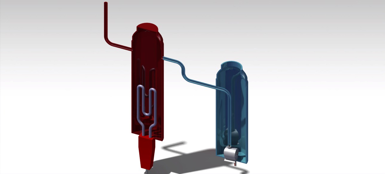
The design that here we present consists of two receptacles to that we can call deposit and heater.
In the first one we would have the miscellany prepared and would penetrate it to the heater by means of a small bomb of water of fishbowl to the deposit when it was necessary.
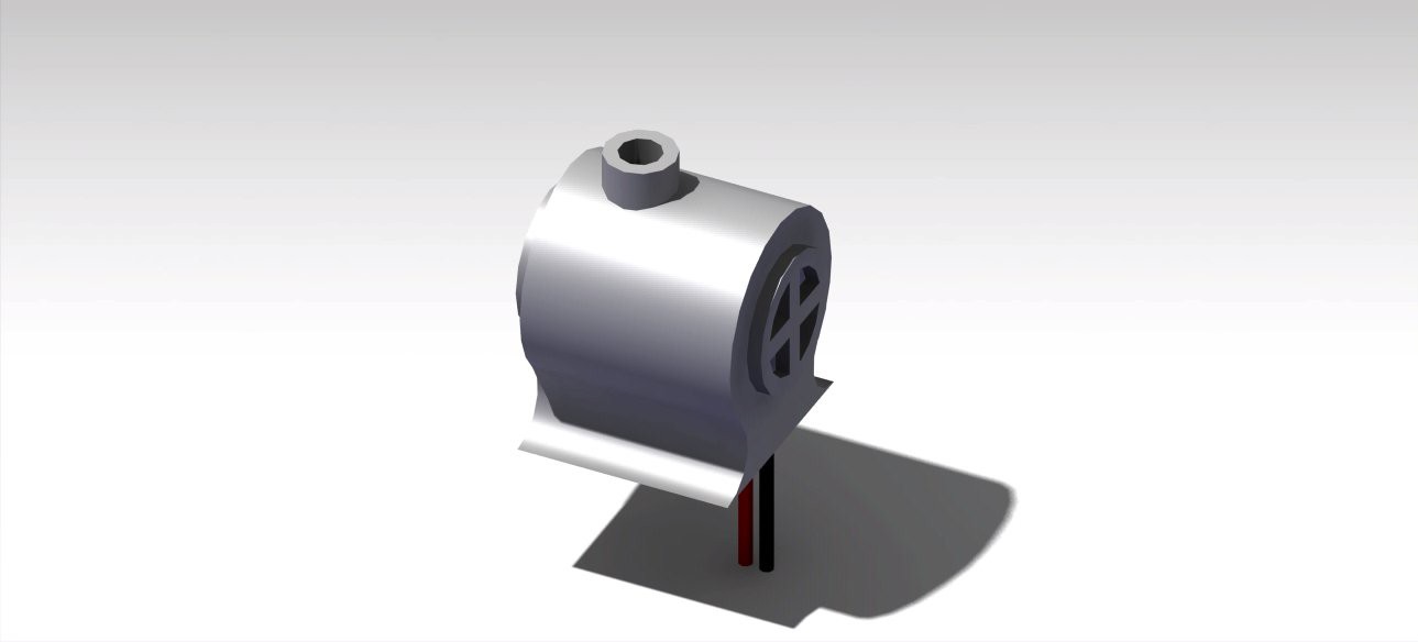
In the second one we would have inside a water kettle for cups that will warm the miscellany generating the smoke that across a pipe will goto the wind tunnel.
HOW TO DESIGN THE CONTROL PANEL FOR OUR WIND TUNNEL
To control the processes that take place in the interior of the tunnel we will need a control panel which allows us to monitor the data from the sensors and act on the fan and the machine of smoke.To be able to have in our hands the control of wind tunnel we designed a control panel that meets the required characteristics.
We are going to recreate a possible study of an object with our wind tunnel to explain the control panel.
With the frequency variator connected to the fan and to the mains and the variator control connected with a cable to the computer started study.
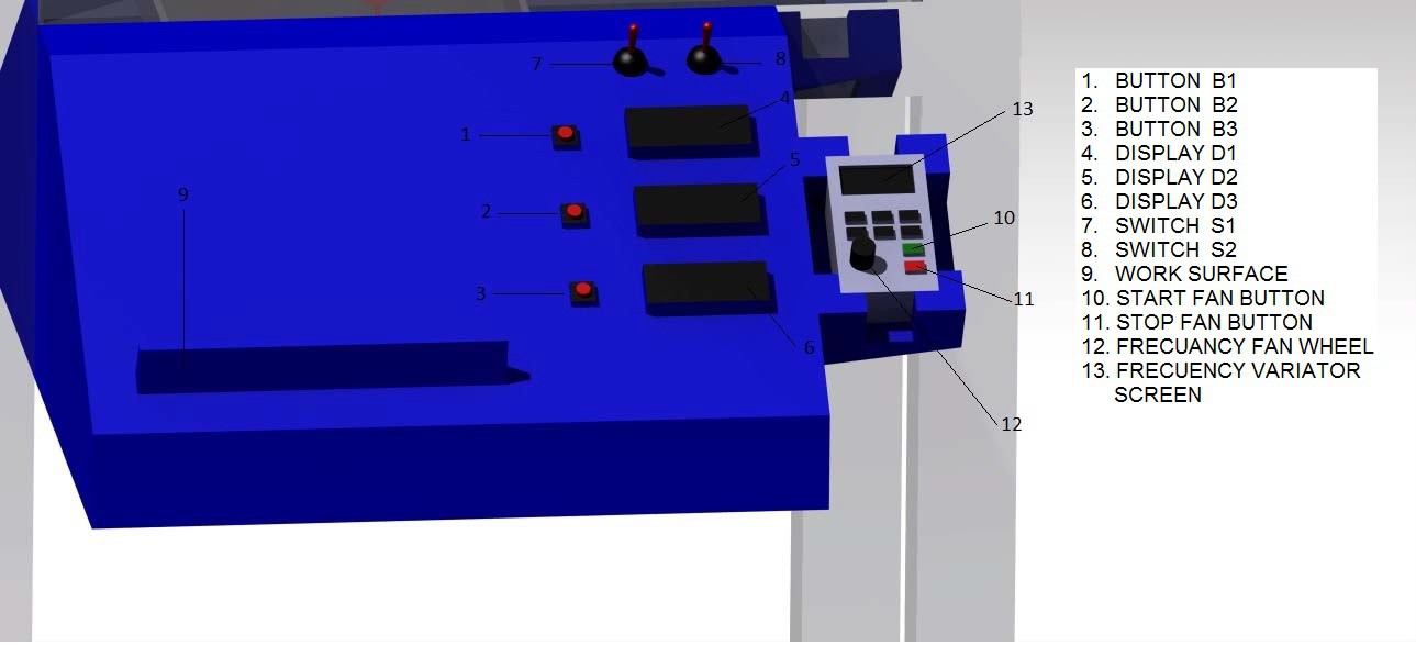
- Press the B Button1 to display the values of speed, temperature pressure and temperature in the displays D1, D2 and D3 respectively.
- Press the START button on the frequency variator and varied with the wheel the frequency of the fan until that in D1 look at the speed of the air that we seek.
- Press B2 to be able to visualize the forces of Lift, Drag and Side Force in D1,D2 and D3 respectively.
- Press B3 to display the values of the moments of Rolling, Yawing and Pitching in D1, D2 and D3 respectively.
- To view the flow of air with the machine of smoke we activate the pump with the switch S1 and when this submerged the kettle in the mix we deactivate S1 and we activate S2 to connect the kettle and We desactivate this when you no longer need smoke in the tunnel.
- When the study is completed press the STOP button on the frequency variator to stop the fan.
CHANGE OF SMOKE MACHINE
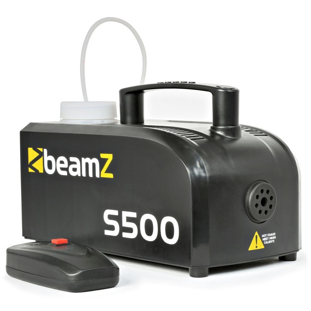
Doing the tests of the smoke machine we manufacture fail to create the flow of smoke needed for testing. The award that received of the contest Citizien Scientist us help to solve the problem buying the machine of smoke BeamZ S500. To adapt it to the tunnel design with Catia ducts that lead the smoke towards the base of the stabilizer.
CHANGE OF MODEL OF OBJECT OF STUDY
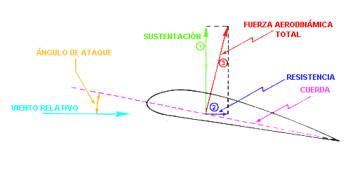
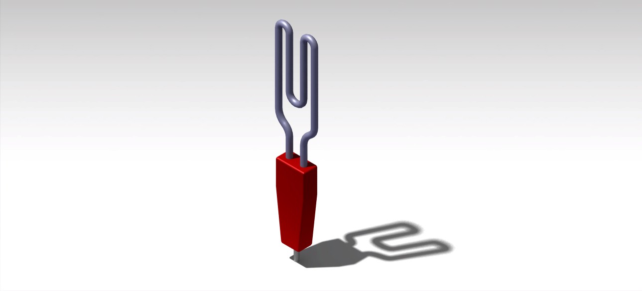
In the first moment the idea that we had age to do an essays camera in that it was possible to mount a three-dimensional model in which we could to measure the forces and moments to the one that was submitted by a scales that was dieñada for such an end. Now we have thought to start with a model of simpler cameraman but in which the visual results us the fluid mechanics allows better comprehension. We have designed a model, which we will construct in wood, and which tries to recreate the profile alar of an airship. We have used the profile alar of a B737 to which we have incorporated to him mobile surfaces that make change the behavior of the profile before the air circulation. We have incorporated a flap and a slat that it will be possible to fit before realizing the study. Of the same form also it will be possible to change the angle of attack of the profile. The profile has been created from the points that have been obtained by the program Profili V2 and later we have introduced it in Catia so that it was creating a continuous line between the points and from here on to realize the design.
CHANGE OF BALANCE OF MEASUREMENT OF FORCES
To measure the strength of the new model of study will be installed in the test chamber two pairs of load cells. The data provided by the sensors allows you to know the resulting force that this submitted the profile at the time at which the fan is performance. Forces and elements that determine the simulation are seen in the following image.