 AngelLM
At Thor's Website will find updated info about this project, manuals, list of materials, the community forum and much more. Visit us!
To develop this project, I have been involved in several areas of expertise:
Hardware choice
In order to have a nice accuracy on the moves without raising the price too much, I chose stepper motors for the movement transmission. I had to choose stepper motors with mechanical reduction for the second and third articulation in order to manage the torque generated in these articulations. For the two last DOF I chose smaller steppers with the purpose of reducing their weight.
For the electronics I chose an Arduino Mega as main controlling board. And I designed a "shield" to make possible the control of 7 steppers. I chose pololu A4988 as stepper drivers.
For the transmission of the third, fifth and sixth articulation I have used GT2 Pulleys and GT2 Belts.
Finally, I chose optoisolators and a micro-endstop in order to establish a home position for the first five articulations. Using optoisolators instead of mechanical stop allows it to rotate more than 360 degrees without colliding with the sensor.
As you may have realized, all of the hardware I have chosen is commonly used on DIY 3D printers.
3D Design
I used FreeCAD software in order to design the pieces of the robotic arm. There are 37 different printable pieces in Thor. For every piece there have been a lot of iterations behind the final one.
Some design solutions are inspired by commercial robots, others are the result of hours of work and others are just serendipitous ideas.
The final design had to be compact and safe. I wanted to hide every motor and every single wire to make it more aesthetic. Also, I designed covers and protections to reduce the risk of entrapment while the user is manipulating the robotic arm.
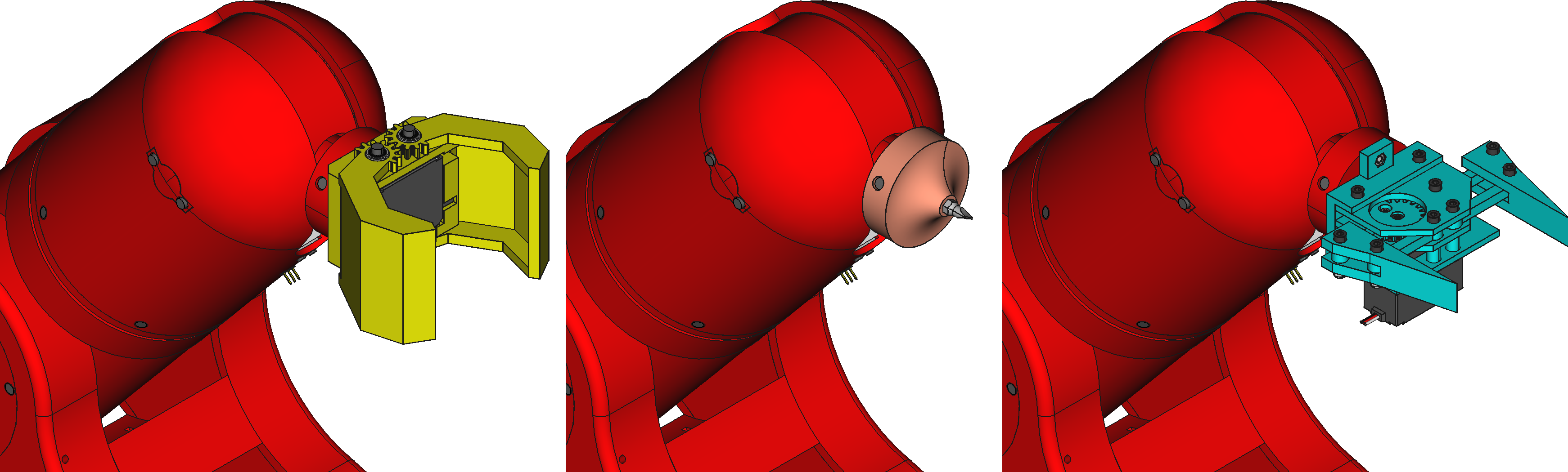
None of the 6 DOF is a end-effector. There are a lot of commercial and DIY grippers/vacuum/hooks around the web and for each use something different is needed. Instead of integrating a gripper into the design I decided to make an adaptable design making an interface between the end-effector and the robotic arm. This way you have 3 options to include a tool on Thor:
1. You can modify the interface, placing the mounting holes wherever you need them.
2. You can modify the tool, matching its mounting holes with the interface ones.
3. You can design an intermediate piece that fit with the interface on one of its sides and with the tool on the other side.
I like the whole robot, but I'm especially proud of these 3 solutions:
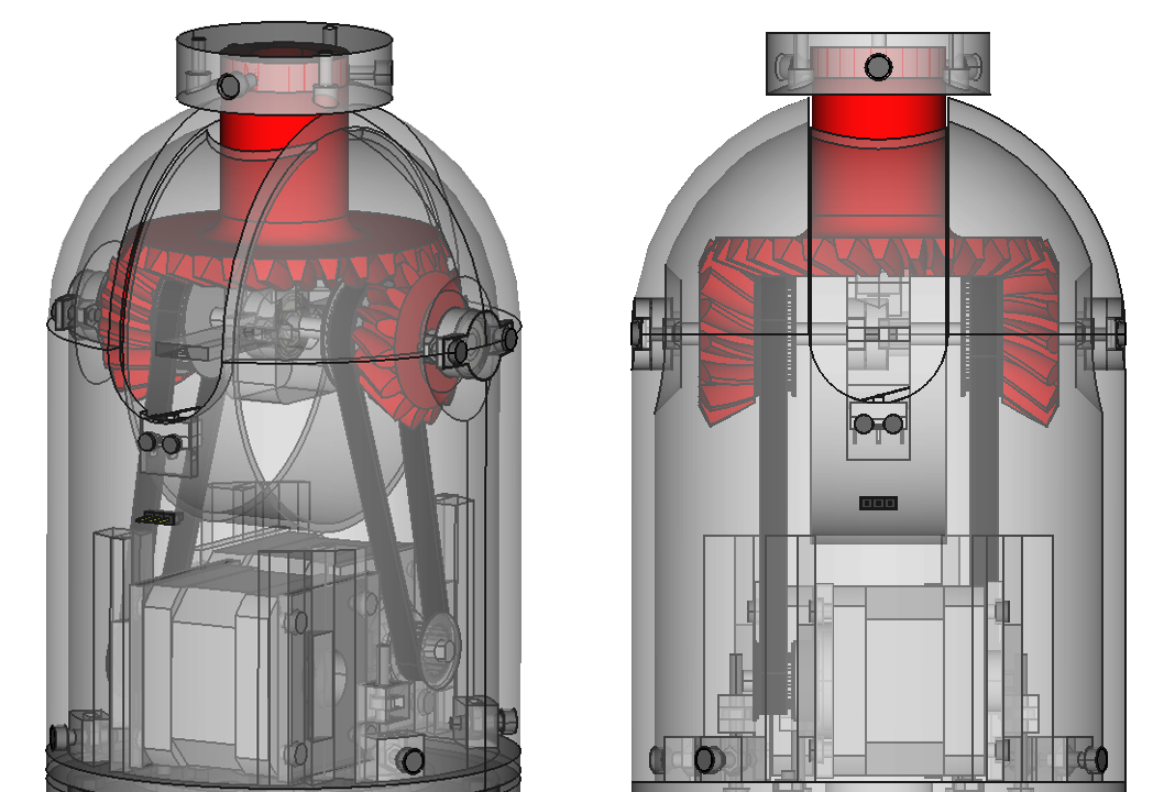
- Semi differential (5&6 DOF)
This kind of transmission allows it to do two types of movements using two small gears that act over a big one. When the small gears rotate in the same direction, the big gear bloks and rotates around the small gears' axis. When the small gears rotate in opposite directions, the big gear rotates around its own axis.
This way, actuating over the two small gears allowed me to place the steppers as lower as I could, transmitting the movement with GT2 belts and reducing the torque generated by the motor's weight.
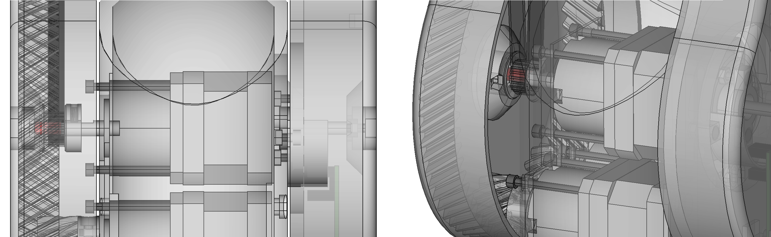
- Support point of 2nd DOF shaft
While I was designing the second and third articulations I was worried about the available space. The motors tookup a lot of space and there wasn't a single small area to establish the second support point for the second articulation axis. The solution was one of the serendipitous ideas I have mentioned early. Why not use the shaft of the stepper of the third articulation as the support point for the second articulation axis? And voila! It worked well.
- DIY Bearing
The design of the 4th articulation had an issue, I didn't find a commercial bearing adjusted to my needs. After days of searching, I decided to make my own. Inspired by a solution that some users used for the Ciclop's bearing, I designed the bearing using 6mm airsoft balls as bearing balls. The result was precise, almost without backlash (after some printing tolerance tests) and very cheap.

Electronic Design
Before this project, I had never designed a PCB but I had used simulation software for electronics in the past. To create Thor, I learned how to use KiCAD and I designed with it the PCB of the shield and the PCBs for the sensors.

The designs of these PCBs were done having in mind that they will be manufactured using a DIY CNC, that's why the paths are only in one layer of copper and their thickness is that wide.
Firmware
I have worked with Marlin firmware before, that's why the first attempt controlling every motor was made using a pair of Arduino Mega + Ramps and Marlin firmware.
After making my own "shield" for the Arduino Mega, I modified GRBL firmware to make possible the control of 7 steppers and 6 sensors.
Manufacturing
At this point it is obvious that I have used a 3D printer to print the pieces of Thor. The most important fact is that the largest printable piece designed is 290mm of depth and I recommend to print it lied flat, that's why I suggest using a printer that has at least 290mm of printing length on one of its horizontal axis.
Regarding the manufacturing of the PCBs, I used a DIY and Open Source CNC machine called Cyclone that I highly recommend.
Future Work Lines
- Structure: It would be nice to redesign the structure to make possible the manufacturing using a combination of laser cut and 3D printing. This way, the time of manufacture would decrease radically keeping the price low.
-Electronics: I designed the Control PCB and it is OK for a prototype, but it is calling for an update to convert it into a complete solution (Control PCB + microprocessor). Using a professional method of PCB manufacture with 2 layers instead of a DIY process could ease the issue of the electronic board at the same time it could reduce its size.
-Firmware: I think GRBL is a nice and powerful firmware, but I also think that there are lot of improvements that can be done to my variation of this Firmware.
-Control: The arm's position is controlled using a open kinetic chain control. It means that the robot cannot react to external perturbations. Using sensors like potentiometers or encoders along with motors could solve this problem. If these sensors were implemented, the use of DC motors instead of steppers would have to be evaluated. Another improvement that could be done in this area is to integrate the Kinetics into the firmware in order to have a nice control of the position.
-Software: Currently I move the arm using the Universal GCode Sender software. I also had success trying to control it graphically using Blender and some python scripts. It would be nice to develop or adapt software to make the control of robotic arms easier.
License
In terms of licenses, I wanted this project to be Open Source because I want anyone to have the opportunity to study, modify and improve it. Given this decision, I designed it entirely using Open Source software. This way, everyone can open the source files and modify them without buying proprietary software licenses (sometimes unaffordable). There is not a single reason for not hacking Thor!
Of course, every single file included in this project is licensed under a Creative Commons Attribution-ShareAlike 4.0 International License.
Thanks!
Until March of 2016 this project was sponsored by BQ, I would like to thank the company and my colleagues because without them, this project would have not been possible.
I have studied at E.T.S.I.D.I. college (Universidad Politécnica de Madrid) where I acquired key knowledges and where I incremented my passion for robotics.
Also I would like to thank Miguel Hernando, who was my Final Degree Project tutor, for his help and awesome tips.
Of course, I also would like to thank my friends and family for the support and the hours of listening.