Eric Tsai
****************** Entry Requirements *******************************
System Design Document: https://electronichamsters.files.wordpress.com/2014/08/system_design.pdf
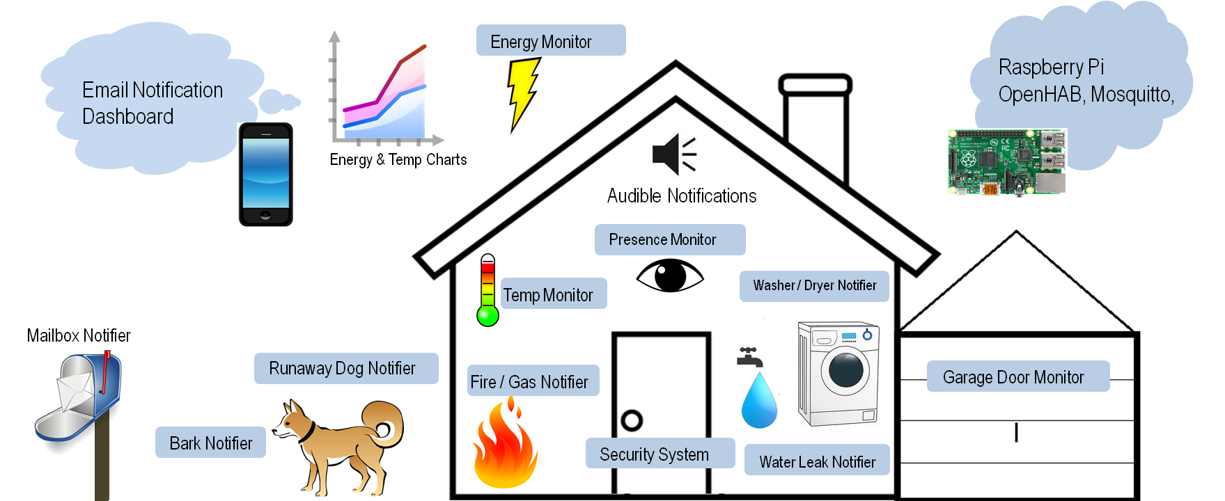
Phase 1 of this project is to provide an over-all design and examples for home automation sensors. Below, you'll find my progress with video demos of each sensor. The basic architecture has been built.
I'll work on providing more example Arduino sensor nodes to fill up a home automation system.
Phase 2 is an experiment with physical computing. Once I have all the sensors set up, I'd like to build a doll-house size replica of my house, with servo controlled windows and doors, and LEDs. When a door opens up in the real house, the replica house's door also opens. Basically, I'd like to come up with a replica house analog for all the sensors I have in the real house.

Here's a video of the garage door monitor that's in this tutorial.
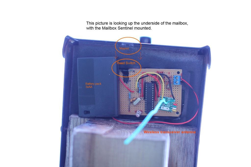
1) "Mailbox Sentinel" - a battery powered Arduino monitors your postal mailbox, and the raspberry pi plays the old AOL "you've got mail" sound clip when the mailbox is opened. It also emails you, and sets the mailbox status on the webpage, reports the time stamp of the last opening, and lets you know the Arduino battery voltage.
Mailbox Sentinel quick demo video
Mailbox Sentinel - Detailed Explanation
2) "Baby Room Sentinel" - same thing, except monitor the temperature in the baby room and alarms when it's too hot or cold. I have a 6 month old.
3) "Washer / Dryer Sentinel" - same idea, have the raspberry pi announce when laundry is done.
4) "Water Leak Sentinel" - email yourself when your house is flooded
5) "Home Intrusion....um...Sentinel" - basically just a twist on the mailbox sentinel, using a PIR sensor instead of a reed switch, and plays a loud alarm noise instead of the AOL sound clip.
6) "Runaway Dog Sentinel" - Emails / alarms when your dog wonders off the yard
7) Hydroponics, home HVAC control, security system, aquarium automation...
_____________________________________________________________________________
What problem does this project solve?
If you googled "Arduino Home Automation", there is no shortage of examples of Arduino being used in some kind of home automation. When I first started looking into using Arduino as sensor nodes to do home automation, none of the examples I found really fit my idea of home automation. Some of the Arduino examples didn't use wireless transceivers, only used ethernet shield. Or they used expensive wireless transceivers, or used transceivers that had very short range. Sometimes the examples couldn't easily be extended to do the breadth of home automation ideas I had, or couldn't easily interface with non-Arduino systems. Some of them required too much programming on the server side (hard programming), or locked you in on the Arduino side (easy programming). There's some cynicism that Arduino can only "kind of" do home automation and IoT, but not completely. From here, I begin to form a list of requirements:
Sensor nodes must:
1) be cheap to make, cost less than $20
2) be power efficient enough to run on batteries
3) have good wireless range
Server must:
1) able to run on windows, mac, or Linux on low power SBC
2) provide encryption and authentication on the web interface
3) provide rules engine (if this, then that)
4) historize and chart data
5) be flexible, accommodate different types of inputs and outputs
I then came across the OpenHAB platform - an existing, sophisticated, well-supported open sourced home automation solution with a full web interface, data historization capability, rules engine, and more communication options than you can shake a stick at. Unfortunately, there weren't any good examples of how to make Arduino talk to OpenHAB. In the mean time, I still wrestled with getting a hardware design and a wireless solution that was cheap and energy efficient enough for battery use.
I think I've finally figured out how to make Arduino talk to OpenHAB in a way that is extensible. And I've also settled on a hardware design that fits the other requirements - cheap, energy efficient, with good wireless range. This Hackaday project is a working example of how to make inexpensive, low-powered, wireless Arduino sensor nodes that connect to an OpenHAB installation. There is no need to script your own web server from scratch, implement SSL/TLS, and write your own rules engine. This is already available from the great open source community with OpenHAB. On this project page, I want to provide a complete, totally reproducible set of sketches and configurations for you to make your own wireless sensor node, using Arduino and OpenHAB to accomplish whatever creative home automation ideas you have.
This project isn't about what I can do, and my examples are only secondary, youtube eye candy. I'm hoping this foundation and these examples help eliminate some of the cynicism about Arduino only being able to "kind of" do home automation.
Phase 1 of the project is the practical home automation portion. Phase 2 is an experiment with physical computing. I want to build a small doll-house replica of my house with doors/windows that are servo controlled, and LED lights in rooms where I have light sensors. Using a Raspberry Pi running a separate OpenHAB installation, this doll house will mimic what's happening in the real house. It'll be like a physical dashboard powered by OpenHAB. When the real house's garage door opens, the doll house garage door would open.
______________________________________________________________________________
How do I replicate these examples? What skills are needed?
1) Do I need to know Linux?
No, not necessarily. I'm running OpenHAB on a Raspberry Pi, which runs on Linux. But OpenHAB can run on a Mac or PC, and all the configuration files are exactly the same. Running OpenHAB on a low power 5 watt single board computer like the Raspberry Pi makes sense for long term use, but it's not a requirement. All my examples are completely reproducible on Windows or OS X. This was an important design goal as it makes the project more inclusive. Your operating system of choice shouldn't exclude you from doing cool projects. I want this to be accessible for teachers and students who might not get to pick their OS.
2) Do I need to solder?
No, not necessarily. I chose to start my battery power builds with the bare microcontroller, strip board, and the wireless transceiver module because I wanted to start from the basics. But you can get the same results using Low Power Lab's Arduino clone with the built in transceiver. See more details below.
3) Do I need to know electronics?
Yes, a little bit. Just as you would to make Arduino projects.
4) Do I need to know how to program?
Yes, even using my example sketches, it helps to be able to read code. And configuring OpenHAB is a kind of programming. There's a steep learning curve with OpenHAB, but it's totally doable. I recommend starting with a desktop installation to play around with.
In short, my examples can be as DIY as you want to make them, but you don't have to start from scratch, and I try to point out opportunities where you can take shortcuts. These examples are very beginner friendly, but the capabilities and potential for home automation is extensive. I'm writing this project not just for the typical Hackaday reader, but for anyone with a mild interest in this stuff.
______________________________________________________________________________
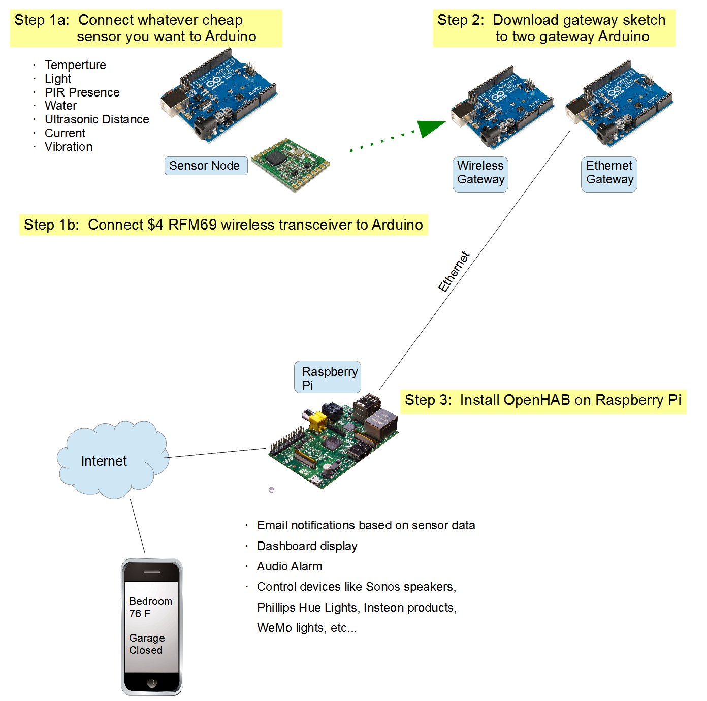
Here's a general description of how the pieces talk to each other. There are 3 main components:
1) OpenHAB, the home automation gateway, running on Raspberry Pi or PC
2) Arduino wireless sensor node
3) Arduino gateway (technically two Arduinos, but they work as one diagrammatically)
To demonstrate my scheme for connecting wireless Arduino sensor nodes to OpenHAB, this tutorial will follow my garage door monitor - an Arduino that looks at the garage door location and tells me if the garage door is opened or closed via the OpenHAB Android app.
| ------------------------- OpenHAB Server ------------------------- |
OpenHAB provides the web interface as well as the computational elements of a home automation system. It can run on a Raspberry Pi, a PC, or some other single board computer. It's the web server for your home automation system. You access the interface through a web browser, Android app, or iPhone app. Whatever your device, the one interface you configure appears the same on the browser interface as well as the mobile apps. The platform has built in security (authentication and TLS encryption), so your user interface can be safely exposed to the internet. I have a phone and tablet running the OpenHAB Android app 24-7. This phone and tablet act as the home automation command center. You can have an Android tablet for every room if you want, with a specific page targeted for each room's usage.
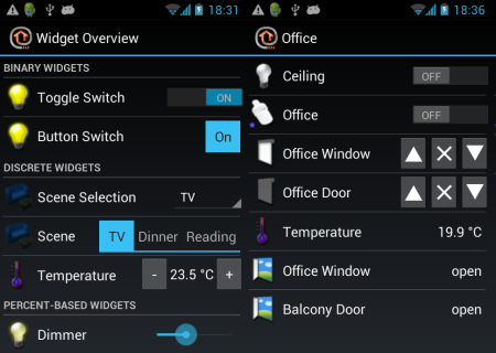
Here's a generic demo screen of what OpenHAB is capable of.
I'm utilizing this platform because it's powerful, flexible, and it removes a lot of the work required to create a web interface. It has all the features I'm looking for in the brains of a HA application:
1) Receive data from multiple sources (I'm showing how to make it receive and react to Arduino data). It can also interact and control a large list of other commercial products, including Sonos speakers, z-wave devices, and Insteon power plugs. I lean towards using Arduino as input devices (sensors) and commercial products as output devices (like a Wemo).
2) Rules engine: "if this, then that"
3) Data historization, for charts of sensor data
4) Actions - send an email based on conditions, send a tweet, send a Android push notification, play a sound on the Raspberry Pi, start playing a song on the Sonos speakers...basically, react to Arduino sensor data or react to Android app push buttons.
| ------------------- Sensor Node ------------------- |
The sensor node is the Arduino. You can connect any sensor you want to the Arduino:
- temperature/humidity sensor ($3)
- photo sensor ($1)
- CO2/smoke sensor ($4)
- current transformer for energy monitoring ($8)
- GPS module ($17)
- ultrasonic distance sensor ($4)
My demonstration shows a wall powered garage door monitor that uses an ultrasonic sensor to see whether the garage door is opened or closed. It reports the door distance data to OpenHAB at intervals and also when big changes are seen. OpenHAB translates the distance into "Open" or "Closed" on the web interface. Once you have an Arduino node, it's so easy and inexpensive to add other sensors to it, so I also added a temperature/humidity sensor and a light sensor to tell me if the garage light got left on.
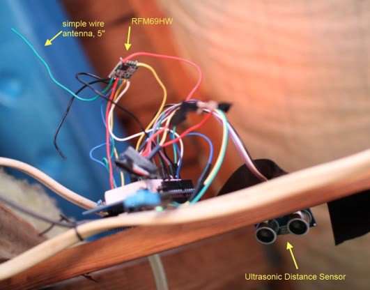
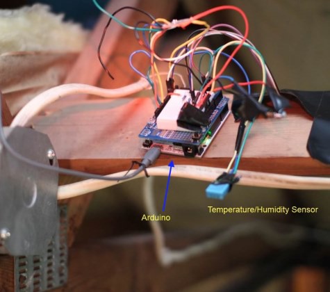
This is the garage door sensor node. It's mounted in the rafters, looking down at the garage door.
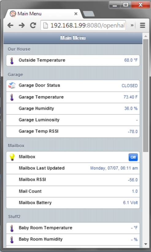
And here's my actual OpenHAB web interface - in this case, it's a screen shot of the OpenHAB web browser interface taken from my PC. The Android screen looks much the same.
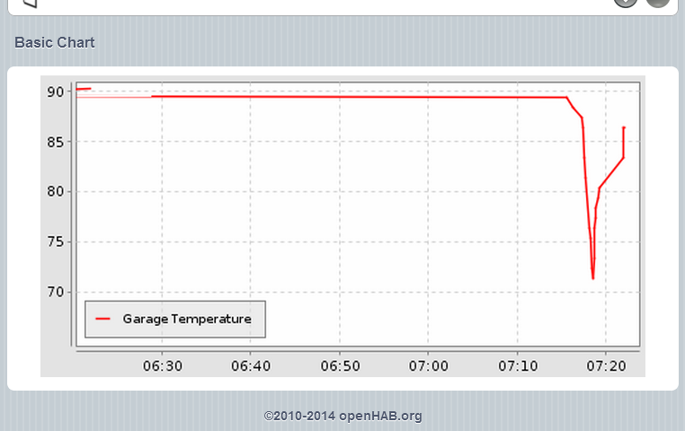
And here's an example chart object. Doing this part required installing mongodb to historize temperature data.
| ------------------------------- Wireless Transceiver ------------------------------- |
Whatever sensors you connect to an Arduino, you have to wirelessly send the data back to the gateway somehow. A key component to the entire Arduino sensor system is the wireless transceiver selection. Several wireless modules were eliminated from consideration early on. I ruled out the wifi module – too expensive and power hungry. Z-wave and Xbee are possibilities, but even the cheapest ones are expensive, and the cheapest ones have poor range. Bluetooth doesn’t have enough range or wall penetration. I’ve personally tested these two different modules: nRF24L01+ and RFM69HW.
The nRF24L01+ is probably one of the best known wireless transceiver modules in the Arduino community. It’s cheap. The low power version is $2, and the high power version is $6. There are multiple libraries available, and the device seems in general to be well supported and widely available. The module and libraries provide basic encryption, so your neighbors can’t monitor your wireless transmissions or actuate your devices. It runs on the 2.4GHz band – the same frequency band as your home wifi. The 2.4GHz band doesn't have very good wall penetration. For me, two high power modules could just barely make it across my house. Start factoring in basements and it gets hairy. I’m also not sure how wifi traffic interferes with the nRF24L01 traffic. Note that I didn’t make any efforts to optimize range by changing the data rates or modifying the antenna. It seems other people were able to get much better range than what I got out of these.
I ultimately selected the RFM69HW for my wireless transceiver. It’s a relative newcomer to the Arduino community, and not as well known as the nRF24L01. The Arduino library for the RFM69HW comes from Felix of Low Power Lab. He pretty much single handedly provides all the support for this library on his forum. Like the nRF, the RFM69 comes in a standard version (RFM69) and a high power version (RFM69HW), and cost around $4
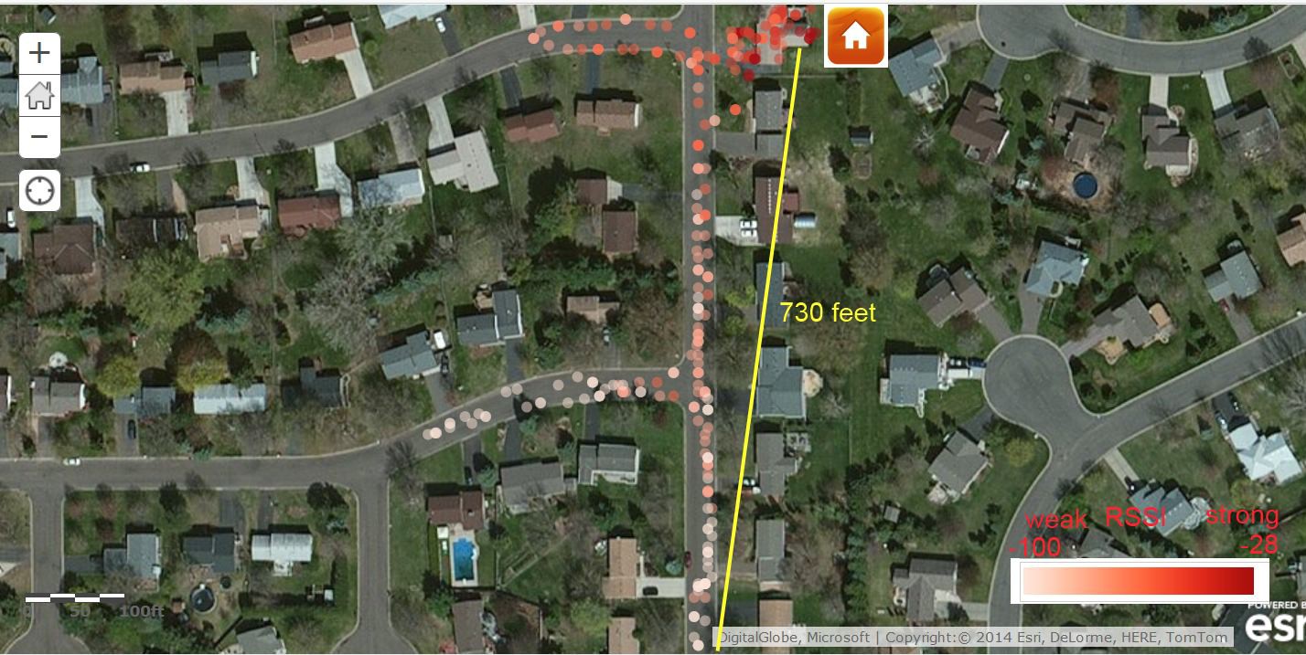
Here is my personal range test of the RFM69HW modules using a simple 5cm wire antenna. The sender is an Arduino with a GPS module, sending the GPS coordinates using a RFM69HW. The receiver is an Arduino with another RFM69HW, receiving the data as a struct and relaying the data via serial monitor to my computer. I then plotted the coordinates along with color coded signal strength data (RSSI) for each transmission. The RFM69HW easily makes it through several walls of the house. Communication was pretty reliable up to 7 houses away! That’s way better than my nRF24L01+ results. It’s not quite an apples-apples comparison – the default data rate on the RFM69HW library was lower than the nRF24L01. Even with that consideration, The RFM69's wireless properties make it a better choice.
One down side with the RFM69HW is that it’s not 5V tolerant. So you either have to power your Arduino at 3.3V like I'm doing, or level shift/voltage divide the pins going to the RFM69HW from the Arduino. It’s not too bad a complication. The RFM69HW is manufactured by HopeRF in China, and it seems you can only get it from their single US distributor, either from ebay or direct from their website. I’ve never had trouble obtaining it, but it seems to be a single sourced component, and perhaps not as widely available as the nRF24L01 if you live in other parts of the world.
However, it is possible to combine different wireless transceiver modules in the end setup, so it won’t ruin the infrastructure if you change wireless transceivers.
To sum it up:
| Characteristic | HopeRF’s RFM69HW | Nordic semiconductor’s nRF24L01+ |
| Range | Over 700ft reliably, good wall penetration with 915MHz frequency | Poor wall penetration, barely makes it across the house, uses the busy 2.4GHz range |
| Electrical Characteristics | Not 5V tolerant, level shifting required for input pins | Is 5V tolerant, easier to integrate into Arduino |
| Power | Both modules use 3.3V for power $6 for the + version | |
| Price | $4 + reasonable shipping | |
| Availability | Single sourced from HopeRF | Seems to be widely available from more than one source |
| Support | Not as well known in the community, but decent support from Low Power Labs forum. | Very well supported by Arduino community, several libraries available |
| Encryption | Both wireless modules offer encryption via shared key | |
| ------------------------------------------------- Arduino Gateway: RFM & Ethernet ------------------------------------------------- |
The key to tying together Arduino with OpenHAB is the MQTT binding. OpenHAB has multiple bindings (plugins) to allow it to talk different protocols, and one such is this MQTT. It’s an open protocol for passing simple messages over ethernet, and is often used by IoT devices for communication. It just so happens that there is also a handy Arduino library that implements MQTT. This portion here is really where my contribution to the project comes in. I'll give an example of using MQTT to bind Arduino data to OpenHAB.
For this to work, you need a central MQTT broker program to receive the messages and disseminate these messages to the message subscribers . Besides running the OpenHAB runtime, the Raspberry Pi is also hosting a MQTT broker program called Mosquitto.
The gateway Arduino receives the wireless sensor data via the RFM69HW. Using a Wiznet 5100 ethernet module and the MQTT library from knolleary, the gateway Arduino posts MQTT messages to Mosquitto. OpenHAB uses the MQTT binding to subscribe to MQTT messages from Mosquitto, which is how OpenHAB receives the sensor data. From there, OpenHAB displays the data on the user interface the way you’ve configured. OpenHAB can also act on the data – it can push notifications to your phone when the values exceed some condition you set.
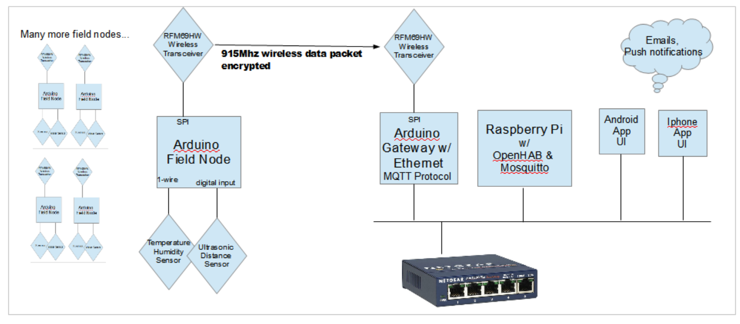
So this Arduino gateway translates wireless sensor data into ethernet MQTT packets. Ideally, I would just need one Arduino that has a RFM69 transceiver and a Wiznet ethernet shield. But I couldn’t figure out how to get both the RFM69 and the ethernet shield working on the same Arduino – they both talk over SPI, and I hit a wall on changing the device select pin on either the ethernet library or the RFM69 library. So my workaround for this problem is to use two Arduinos – one equipped with the RFM69HW, the other one equipped with the ethernet shield. The RFM-equipped Arduino simply forwards the wireless data to the ethernet-equipped Arduino via I2C master/slave communication.
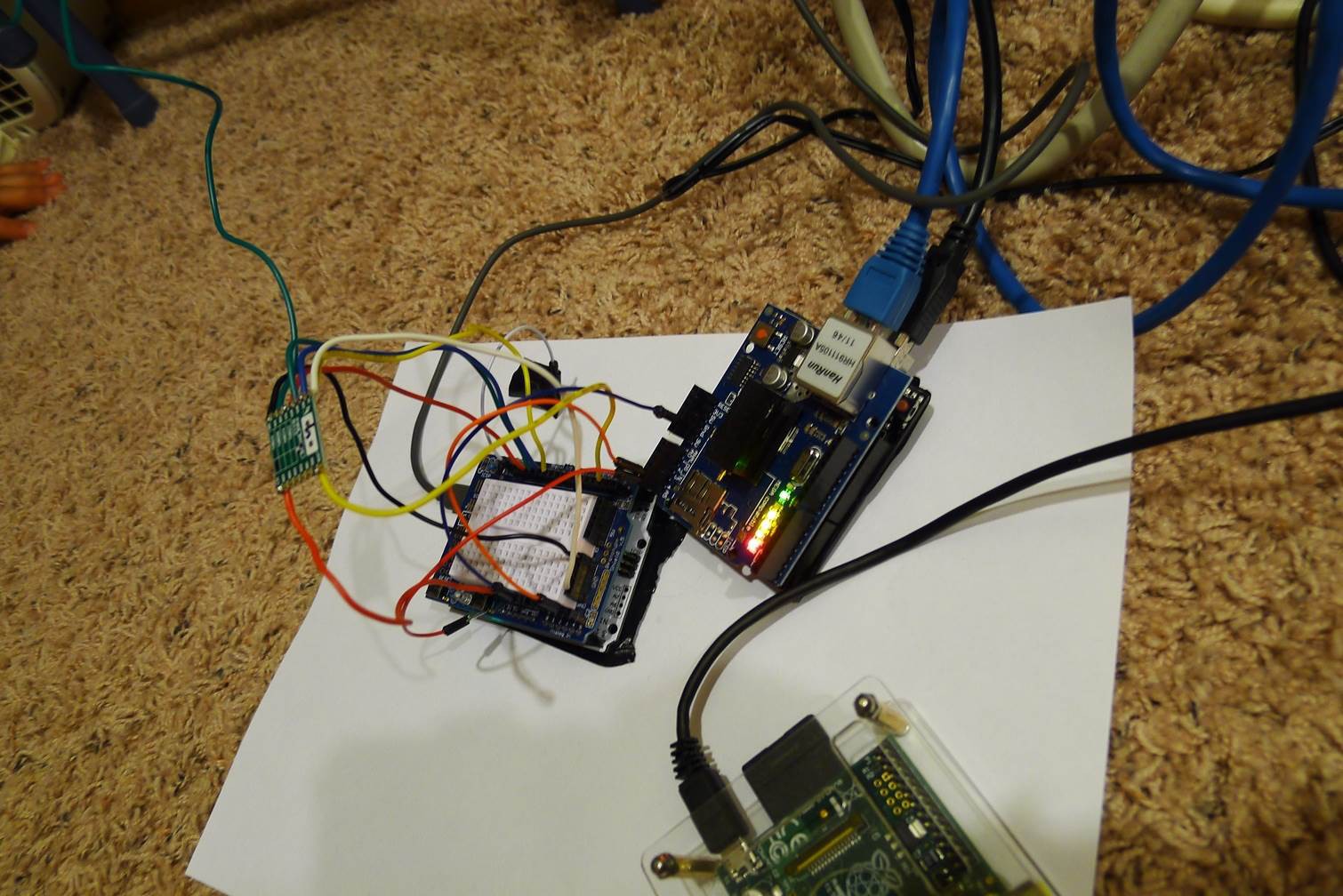
Here's a picture the two Arduinos tied together by the wires used for the I2C communication. The one on the left is the RFM gateway (you can see the wireless module and the green antenna wire). The ethernet arduino is on the right, with a Wiznet 5100 ethernet shield. You can see my Raspberry Pi below them.
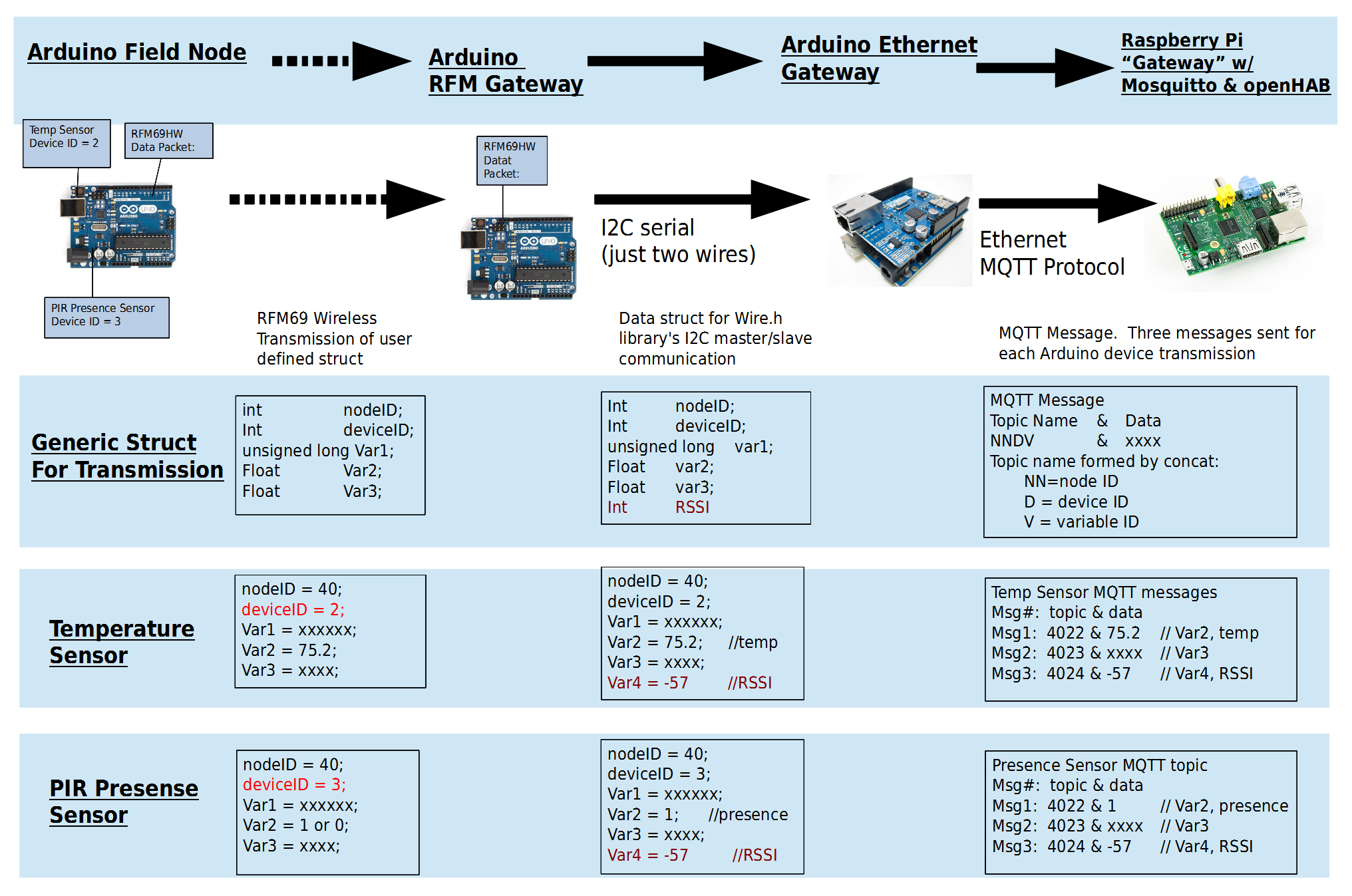
And here's a diagram that explains in more detail how I structure the wireless data, then translate them into MQTT topic/message combos. Use this diagram to follow along in the code. This diagram also explains the item configurations for OpenHAB. The main goal of this scheme is to avoid having to touch the gateway Arduinos when you add sensor nodes. The gateway Arduino should just work once you have it set up. When adding a new sensor node, the only configuration change needed is on OpenHAB, and is done by ssh into the Raspberry Pi.
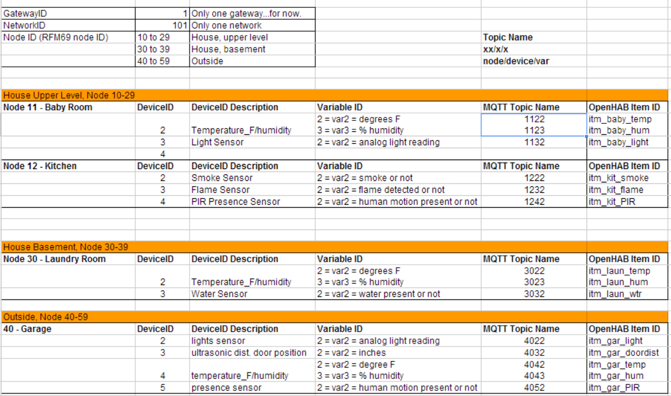
Keep a spreadsheet of your nodes and devices, and their associated topic names like this. The topic naming scheme is arbitrary, and it might've been easier to use words instead of all numbers, but you get the idea.
With the receiving RFM69, you can also capture the "RSSI", or wireless signal strength of the last received data. I'm publishing this to the broker since it's free data. That way I can tell just how close I am to not receiving the wireless transmission.
At first, I thought having separate Arduino's handle the RFM Gateway duty and the Ethernet Gateway duty was a shortcoming. But this design actually allows more flexibility. If you don't like RFM69 modules, or you don't like my Arduino hardware design, you can shoehorn your own Arduino and your own wireless network- the only constraint is that you pass on the data to the Arduino Ethernet Gateway. So, if you don't want to solder your own Arduino, you can buy a better-designed Arduino clone with built in RFM69HW module from Low Power Lab. If you need 1km range, shoehorn in a pair of Flutters. If you don't like my hardware design, you can still use OpenHAB and MQTT, and my scheme can still be applied to whatever wireless Arduino setup fits your needs. Perhaps you'd like to use David Cook's ATtiny for your sensor nodes. No problem! Just switch out the RFM Gateway with one that matches your communications protocol.
| -------------------------- Home Automation -------------------------- |
So none of this is really “home automation”. It’s just sensing data and displaying stuff on a webpage. The automation part is handled by OpenHAB, and you can get a much clearer idea of the possibilities by going over to the rules section of the OpenHAB wiki. As an example, you can have the Raspberry Pi tell you about the garage door by adding a few lines in /configuration/rules/demo.rules:
rule “Say Garage Door”
when
Item itm_garage_door changed from CLOSED to OPEN
then
say(“Someone opened the garage door, Batman!”)
sendMail("myemail@gmail.com", "Garage Door Opened" , "OMG")
end
Text to speech come with the package, no extra charge. Replace the $2 ultrasonic distance sensor with a $2 PIR presence sensor. You can have it announce that someone is at the door, or send a email to you when presence is detected. OpenHAB makes it really easy to do these things.
| -------------------------------------------------------------------------------------------- Circuit & Power Options (Wall Powered vs. Battery Powered) -------------------------------------------------------------------------------------------- |
Your sensor node can be wall powered or battery powered. Here's some guidance on both options.
Obviously, a wall power unit is much easier to build because you can just buy an Arduino clone and use dupont wires, so no soldering. And you don't have to worry about preserving battery power by reducing sensor reading frequency. As long as the location of the sensor node has a convenient plug, you're good. Pick one of the Arduino Uno clones rather than an actual Arduino Uno. I recommend the “Buono”. You can find it on ebay for $9 usually. These clones have a 3.3V/5V switch. You have to use the 3.3V option to connect the RFM69HW because the transceiver will get damaged at 5V. If for some reason you really need to run the Arduino at 5V, use a level shifter or voltage divider between the output pins of the Arduino and the input pins of the RFM69HW. The clones also have a higher current capacity for 3.3V power. You need 130mA at 3.3V when the RFM69HW is transmitting the full 20dB power setting.
Follow the Low Power Lab's circuit for wiring the Arduino and RFM69HW.
If you want a battery powered node, there is one no-solder option. The easiest way is to buy a “Moteino” from Low Power Labs. This is an Arduino clone that has the RFM69HW built in. Felix Rusu, the guy who runs Low Power Lab, makes this and he also wrote the RFM69 library. A lot of my research came from Low Power Labs so I've read a lot about the Moteino, but I've never used it before. If you go this route, I'd appreciate some feedback.
You can also make your own Arduino. Doing it this way allows you to set the clock frequency more appropriately for 3.3V operation, so you can run at a slower 8MHz instead of 16MHz. There are a lot of guides online for this, so I'll just list the general steps and which tutorial I used:
1) Burn a boot loader. I recommend getting a blank ATMEGA328P-PU (without the Arduino bootloader) so you can burn the optimal bootloader for battery use. I burned the “Arduino Pro / ProMini 3.3V 8Mhz” board, using this tutorial:
2) Soldering/wiring: Once you got a working ATMEGA328P-PU with an Arduino bootloader on it, you have to assemble it into a circuit. You could bread board the whole thing...that would be easiest, and saves a ton of time. I followed Low Power Lab's circuit for the Moteino, and pretty much used his components list, but with through-hole parts.
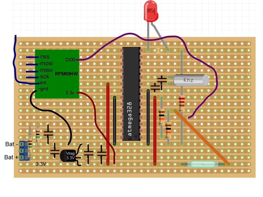
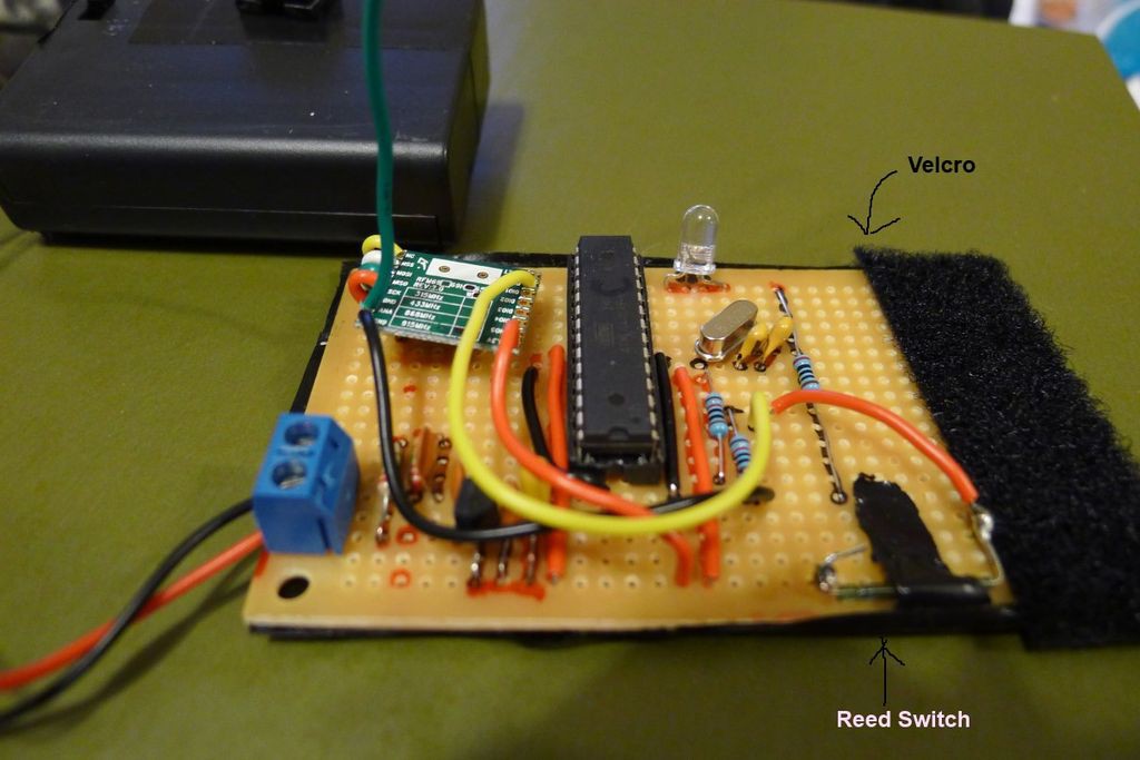
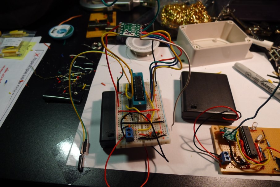
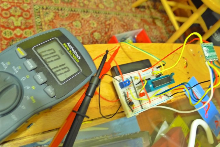
Below I'm showing the same circuit as a bread board and as a soldered strip board. The strip board is the Mailbox Sentinel. The bread board is pretty much the same circuit as the Mailbox Sentinel, except with a vibration switch instead of reed switch.
For a battery powered option, you should try to use interrupts to wake up the microcontroller. See the sketch for the Mailbox Sentinel in the code section below. Using interrupts, the microcontroller sleeps 99.9% of the time. When sleeping and turning off A/D and BOD via code, I got my setup down to about 0.1mA, or 100uA. At 100uA, the microcontroller can last over 2.5 years on 4xAA batteries (2000mAh @ above 4.0V). Add in a couple wireless transmissions a day and battery voltage reading using A/D, the battery life gets cut down to about 14 months. I think there's some room for improvement here, but I can live with those numbers for now.
| ---------------------------- Credits and Thanks ---------------------------- |
My setup uses mostly open sourced software: the Arduino MQTT library, the Arduino RFM69 library, Mosquitto, and OpenHAB. Just to be clear, I didn't contribute to these tools, I'm merely a user. Special thanks to Felix from Lower Power Labs for making the RFM69 library and getting the word out about this great wireless module. Thanks to Jan-Piet Mens for his MQTT tutorials. Thanks to the OpenHAB developers and community - before finding OpenHAB, I was trying to learn socket IO, node.js, and SSL just to make my Arduino data visible from the internet. And thanks to Jeelabs and Nick Gammon for sharing information about low power hardware design and programming.
My contribution, the innovative part if I may be allowed to call it that:
1) Detailed range testing map of the RFM69HW modules using GPS module
2) Example scheme and Arduino sketches for linking wireless Arduinos together, and for passing the sensor data via MQTT protocol to OpenHAB. And good documentation and diagrams to explain what I'm doing. All my work is open source, license under CC-BY-SA, https://creativecommons.org/licenses/by-sa/2.0/
| ------------------ Future Work ------------------ |
Before the Hackaday Prize competition deadline, I'll add some more video demos. I also need to come up with a scheme for Arduino outputs. I tend to use Arduino as sensors, and let OpenHAB handle the output to commercial products to turn on lights or whatnot, but others might want to use Arduino to...well turn on an LED I guess :)
Even with all the great information out on the internet, I'm pretty sure I got some stuff wrong, and there's definitely room for improvement. For example, I'm getting higher current draw than the specs predict for my battery powered Arduino. I welcome any suggestions for improvement in the comments section, or contact me directly.
---------------------------------------------------------------------------------------------------------------------------------------
Demos and Tutorial
All my code, schematics, and configurations are on my github.
Pictures from the Mailbox Arduino setup