Dan Julio
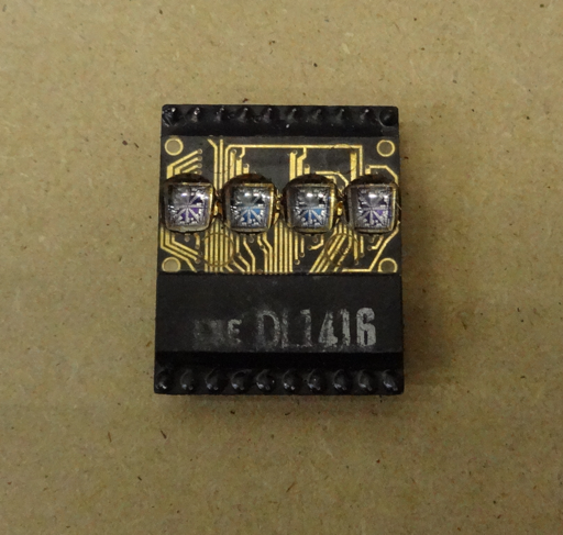
The DL1416SmarTerm is a mishmash of various old and new components that presents itself as either a VT102-ish compatible terminal or a Tiny Basic computer both using a 12 line x 48 character LED display. It gets its name from the intelligent LED module its based around.
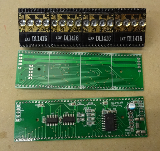
The Siemens DL1416B is an 8-bit parallel write-only device that can display 64 ASCII characters from a built-in ROM on its 17 LED segments. It also supports a cursor that can appear, non-destructively, over any character position. Five of these displays were used on the Rockwell AIM 65 computer for a 20-character display. I decided to take a modular approach to building the terminal display by putting 4 display modules on a board controlled by a local micro-controller (16 characters). I chose the Microchip PIC16F1459 because I had experience with it and it could support both a CDC-class USB serial interface as well as a TTL serial port. It didn't have enough pins to drive data, address and control to the display so I used a pair of shift registers. The boards are designed so that they can be daisy chained via the TTL serial signal.
My friend had given me 213 displays so I decided I'd design for a 64 character by 16 line display which was at the low end, but common for some devices in the 1970s. Each board could be strapped for one of 4 column positions and one of 16 line positions. Firmware running on the PIC keeps track of the cursor position across the entire display and only updates its displays if it "owns" the cursor. The firmware also interprets several control characters for special functions and an escape sequence for cursor positioning.
I ordered parts for the full display and had a nasty surprise when I started assembling and testing. A couple of the tubes of displays contained nothing but bad parts. I had expected some fallout but now had no-where near enough displays to build the full 64 x 16 screen. I tried to disassemble a display but the entire thing was potted and there was no way to fix anything. So after testing all displays and discarding the completely dead ones and the ones with bad segments, the project was scaled back to 12 lines of 48 characters each. An additional complication was that the displays came in 7 different brightness grades. I tried to disperse them in a gradient across the display. Visually the result is ok although the different brightnesses are more apparent in photographs.
During firmware test, I found an error in the spec. It claims that the cursor position is controlled by the address lines but I found that I had to put a bitmask on the data lines. Later firmware testing revealed a few bugs related to cursor updating on a bunch of boards in parallel but overall it was fairly quick to get the displays up and running.
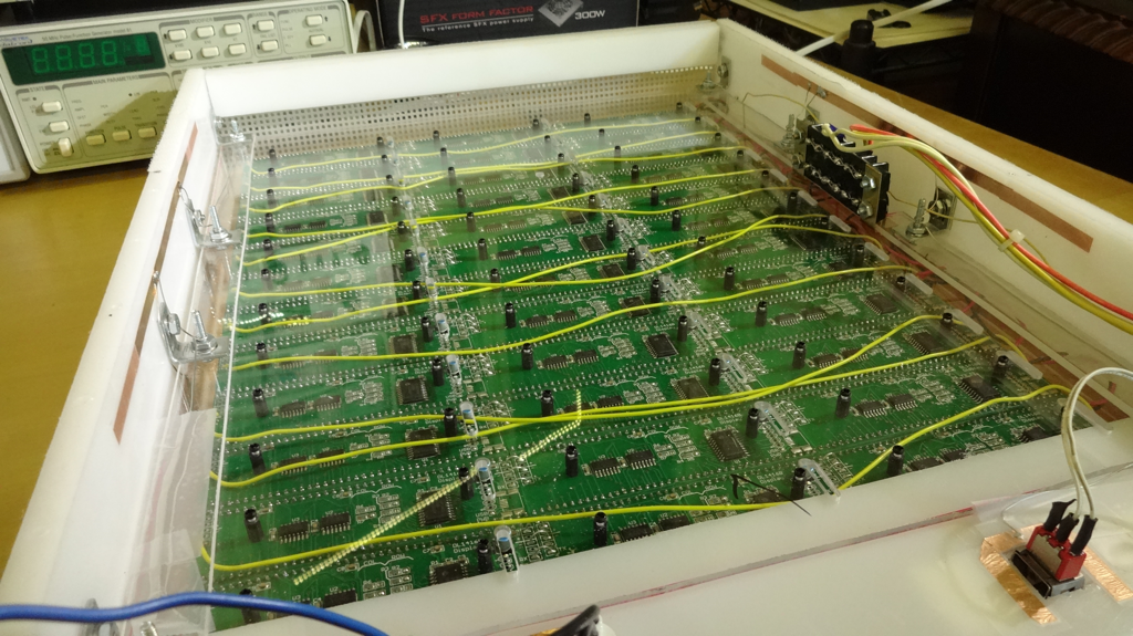
We used the shop-bot at Solid State Depot to route a piece of plastic to hold the displays in an array and also provide access to the ICSP programming port (for which I was thankful because I did one firmware update after all the displays were assembled together).
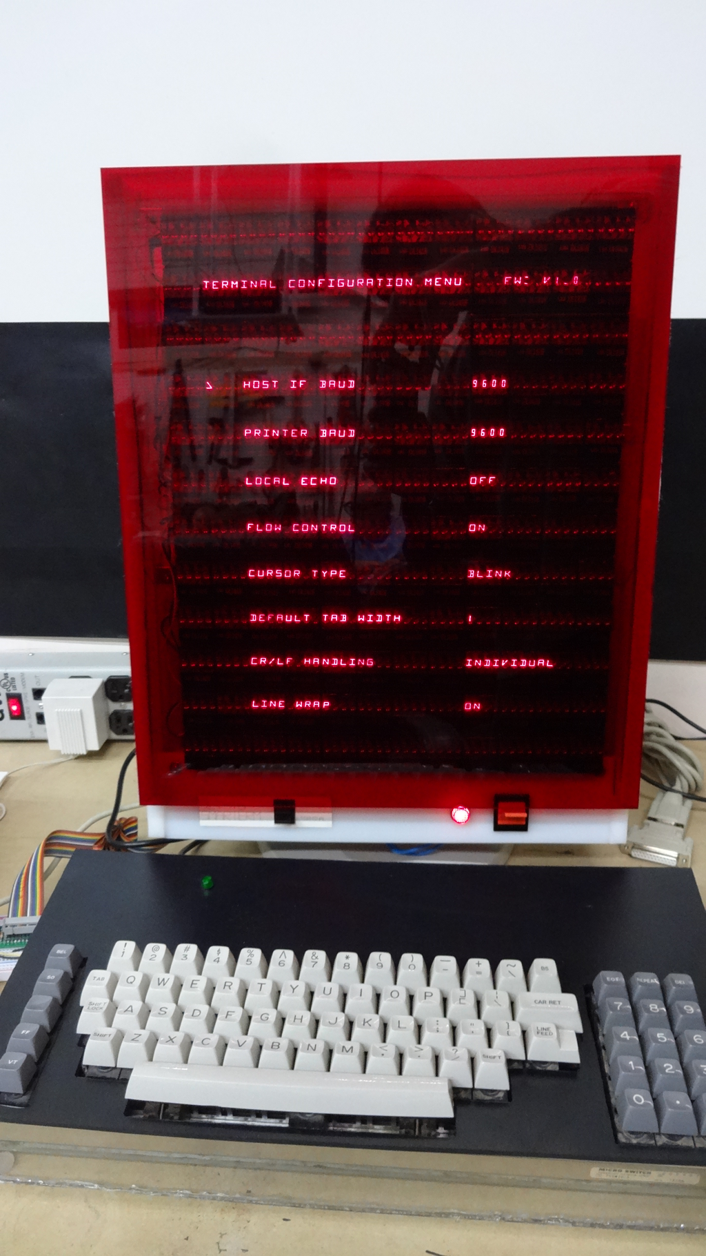
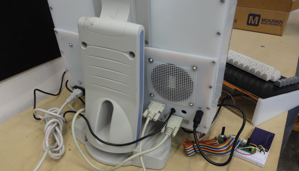
Next up was starting to assemble an enclosure. I decided to try to use only materials I had or I found at the hackerspace which turned out to be HDPE plastic. The motor controller for the shop-bot got damaged so I ended up hand cutting and routing. One interesting thing was having to deal with static electricity. I ended running a strip of conductive tape around both the terminal and keyboard enclosure and tying it (at least in the computer) to ground. I ordered a cut piece of transparent red plastic for the front bezel. A pair of old paddle switches and neon power indicator rounded off a look that I hope is reminiscent of the plastic and mod looks of machines from the 70s.
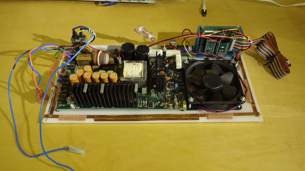
I choose a PJRC Teensy 3.1 as the brains of the device since it had plenty of RAM and 3 serial ports in addition to the USB host port. One serial port was dedicated to the DL1416B displays and keyboard. A second as a host RS232 port and the third as a printer RS232 port. I put an op-amp butterworth filter and LM380-based amplifier on the DAC output of the Teensy so that I can eventually add sound generation beyond the "beep" the keyboard generates. Nine signals (supporting analog, digital and 3 PWM) are brought out on a ribbon cable as a "Hacker Port" accessible from Tiny Basic commands. A SD Card is pressed into use as file storage for Tiny Basic programs (a ridiculous 16 GBs...).
Each display board of 16-characters can take up to 250 mA (about 9A total) and the keyboard requires about 500 mA at 5 volts so a beefy 5V power supply was included. Its 12 volt output was used to power a fan and the amplifier (though additional filtering). The fan is marginally useful (this computer doesn't require that much cooling) but I liked the idea of a device like this having a fan sound like computers of old. Unfortunately I didn't really make a schematic of the Teensy circuitry since it grew over time. It's fairly understandable by looking at the code but I'm happy to ask any questions if someone wants to know more.
I wrote the terminal emulator code which uses a "shadow memory" feature in the DL1416 display board firmware to make rapid-appearing updates. I found Scott Lawrence's great "TinyBasic Plus" which was based on Mike Field's port to use as the basis for my Tiny Basic. I decided to make the terminal ANSI compliant (as much as was possible for a 12x48 upper-case only, single font-size display) so it could also be used with more modern computers. I have logged into both a Raspberry Pi and my Mac using the terminal.
I'll add more detail in project updates. The Teensy 3 code is in the linked github project.
Because of the bad displays I have a few DL1416 board without displays I'd be willing to sell for cheap (+ shipping) if anyone is interested. I have seen the DL1416B displays on ebay from time-to-time. I'll even load the latest firmware (which is in the attached zip file). Contact me if you are interested.