The final version is much more polished. Photos of it along with more details are below!
Note* I started this project with an already modified K40. We cut down the exhaust intake to give us more room in the Y axis. If you want to use this design then you will likely need to do the same, or remove the part of the exhaust where it is closest to the bed of a stock K40. If you don't, you should still be able to make this work, however you will have to trim the aluminum to different sizes, and get a different belt length.
Parts
Hardware
(Note that these are the exact parts that I used to model this, so if you use parts with slightly different dimensions, then you will need to modify the 3d models)
1/2" X 1/16" thick aluminum angle (8ft long - Menards, Home Depot, etc)
These are the sizes that each piece will need to be cut to.
- 3 X 300mm long (X axis)
- 2 X 120mm long (X axis)
- 4 X 160mm long (Y axis) These may need to be different if your K40 wasn't modified like ours
- 4 X 100mm long (Z axis)
8mm linear rod (At least 450mm in length)
(I used chrome plated rod, but drill rod will work just as well for this application. You won't use the Z axis as much as you would in a normal cnc application)
- 4 X 110mm long (You can get some cheap chrome plated stuff Here )
M8 1.25 Threaded rod (At least 500mm in length)
- 3 X 110mm long (This is basically what I used for Threaded Rod X 2)
- 1 X 140mm long (this is if you want the manual override knob)
M3 Threaded rod
(This was kind of a last minute addition. I used this for the belt tensioning mechanism, but there are better ways of doing it)
- At least 300mm in length
8mm Bushings
- 4 x 8mm i.d X 10mm o.d X 10mm long bushings. (I used these exact 8mm bushings. If you use any others than you will need to adjust the 3d models accordingly)
GT2 Pulleys
- 4 X 20 tooth 8mm Bore (I bought them Here )
- 1 X 20 tooth 5mm Bore (I had one lying around but it can also be bought Here )
608 Bearings
- 8 X 608zz ball bearings (You can get a pack of 10 Here )
C clips
- 4 x 7mm C clips (These will attach to the bottom of the threaded rods)
Heat Inserts
(these are used to add threads to all the 3d printed parts. I just used a soldering iron to press fit them)
- Aprox. 40 X M3 5X5mm heat inserts (I bought mine Here )
- At least 2 X M5 heat inserts (not sure of the exact diameter used, but the wholes are 8.2mm in diameter, so your insert must have a slightly larger diameter than that)
Screws
- 2 X M5 x 28mm (26 - 28mm should be long enough. I had to cut some to length)
- At least 30 X M3 x 10mm (I would just buy some in bulk, but 10mm should be long enough for everything. If you plan on drilling and tapping the aluminum angle though, then you will need more than 30)
- 4 X M8 1.25 Nuts
GT2 Belt
(This is the one critical thing where the exact length does matter. We are using a closed loop belt, so I had to order an exact size. Getting one too large will increase the amount of slack, and getting one too small will make it useless) Remember that I started this with a modified K40, so you may need a different belt length depending on your K40!
- 1 X 6mm wide 1210mm long GT2 closed loop belt (This is the only source that I could find)
Nema 17 motor
- 1 X 34mm long Nema 17 motor. (The length of the body is somewhat critical for clearance issues, so I wouldn't get one any longer than 34mm) This one will work.
Endstop Switches
- 2 X SPDT switches (I used these but I would not recommend them. Basically any similar micro switch will work)
Aluminum Bed
- 1 x 350mm X 250mm bed. (I used this, but it is almost overkill for this application. Pretty much any expanded aluminum or laser bed material will work)
3d Printed Parts
All of the STL files can be found Here
I have also provided the STEP files in case you need to modify the 3d models at all.
I printed all the parts in PETG with 3 shells and a 20% infill.
You will need to print
- 1 x Knob.stl (for manual adjustment of the Z axis)
- 2 x Bed Mount.stl (This is what the aluminum bed attaches to)
- 2 x Bed Mount Mirrored.stl
- 2 x Bed clamp.stl (this is what clamps the aluminum bed to the Bed Mounts(washers work too))
- 2 x Bed clamp mirrored.stl
- 10 x Base clamps.stl (These clamp the aluminum angle to the 3d printed parts)
- 2 x Base Corner.stl (Bottom corners of the structure)
- 2 x Base Corner Mirrored.stl
- 1 x Motor Mount.stl (self explanitory, but it also mount 2 x 608 idler bearings)
- 2 x Top Corner.stl (Top corners of the structure)
- 2 x Top Corner mirrored.stl
- 8 x Top clamps.stl (Base clamps will work too, these are just a bit stronger)
- 1 x Tension Adjuster.stl (Tensioner mechanism using m3 threaded rod and 2 x belt tensioners)
- 1 x Tension Adjuster Knob.stl (makse tensioning the belt easy)
- 2 x Belt Tensioner Top.stl (Top of tensioner assembly)
- 2 x Belt Tensioner Bottom.stl (bottom of tensioner assembly. This snaps together with the top)
- 2 x Bearing M8 Washer.stl (these are for the idler bearings near the motor)
- 2 x Bearing Mount.stl (attaches the 608 bearings to the motor mount using the M5 screws)
- 1 x Z max endstop holder.stl (attaches the endstops)
- 1 x Z min endstop holder.stl
Assembly
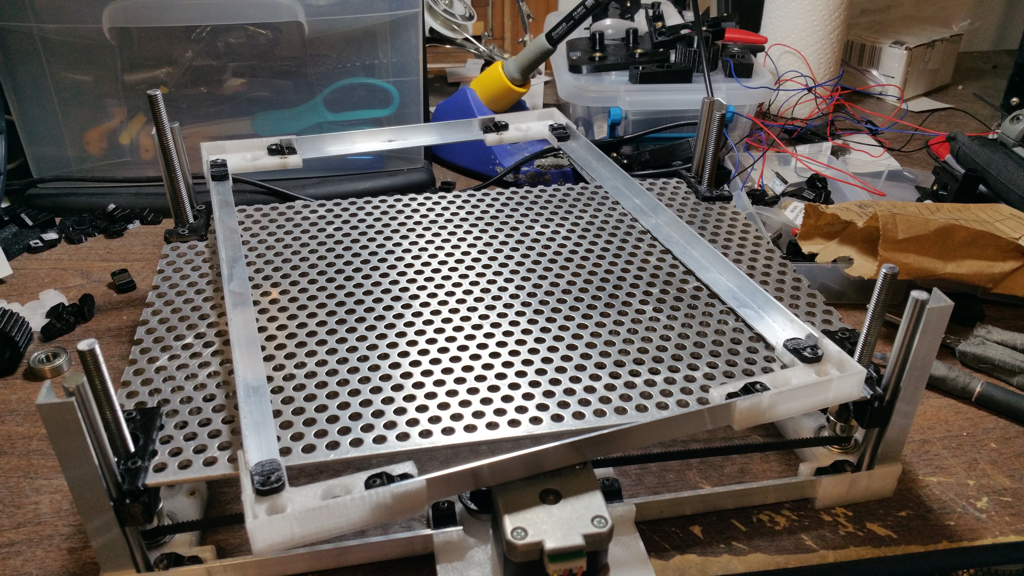
This is what it should look like when completely assembled. Unfortunately I can't go into detail with the assembly, but it is pretty straight forward and I will attach a bunch of photos that should show how it all goes together.
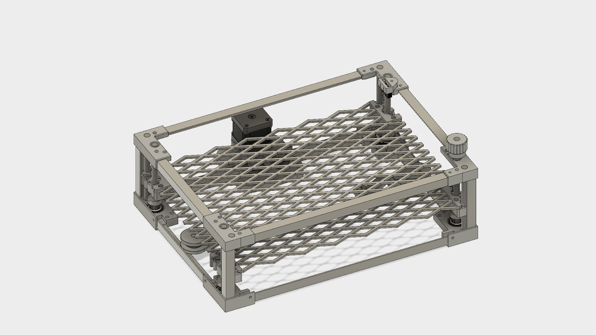
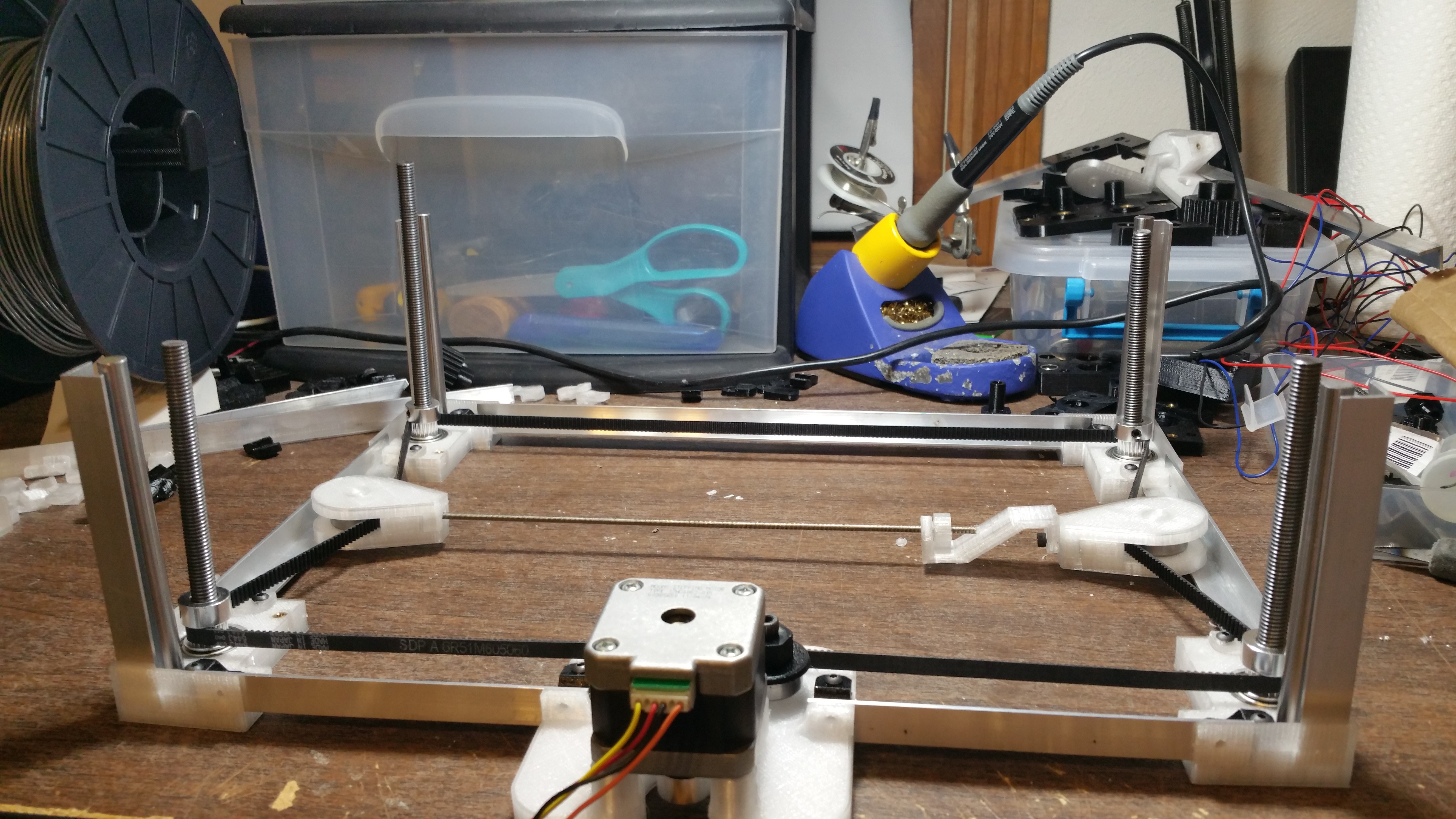
 This is most of the base assmebly. You can see the black clamps that hold the aluminum angle and some clear ones. The clear ones are smaller to have enough clearance for the belt.
(the black printed parts are just from a previous itteration. aka I ran out of black plastic)
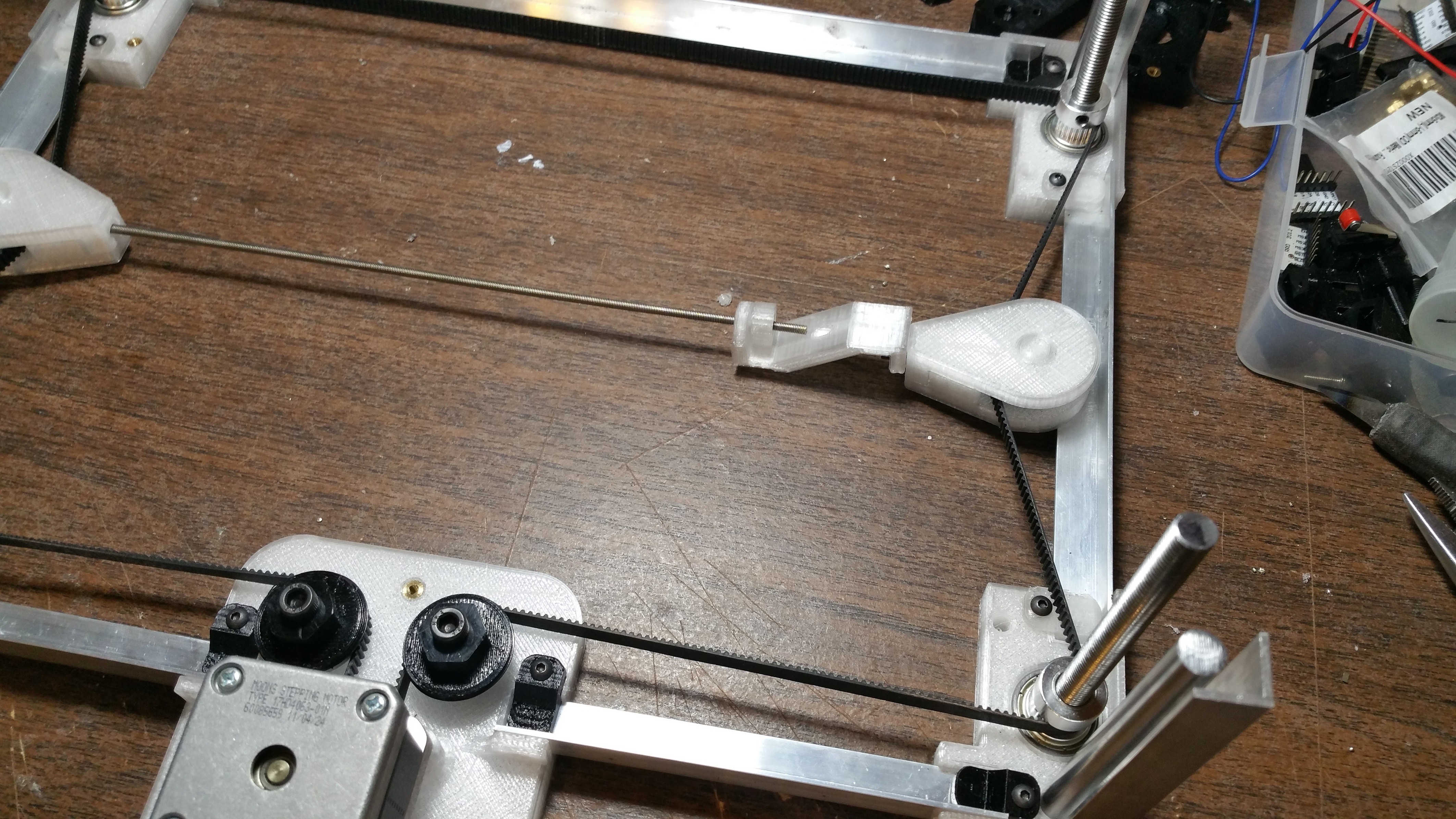
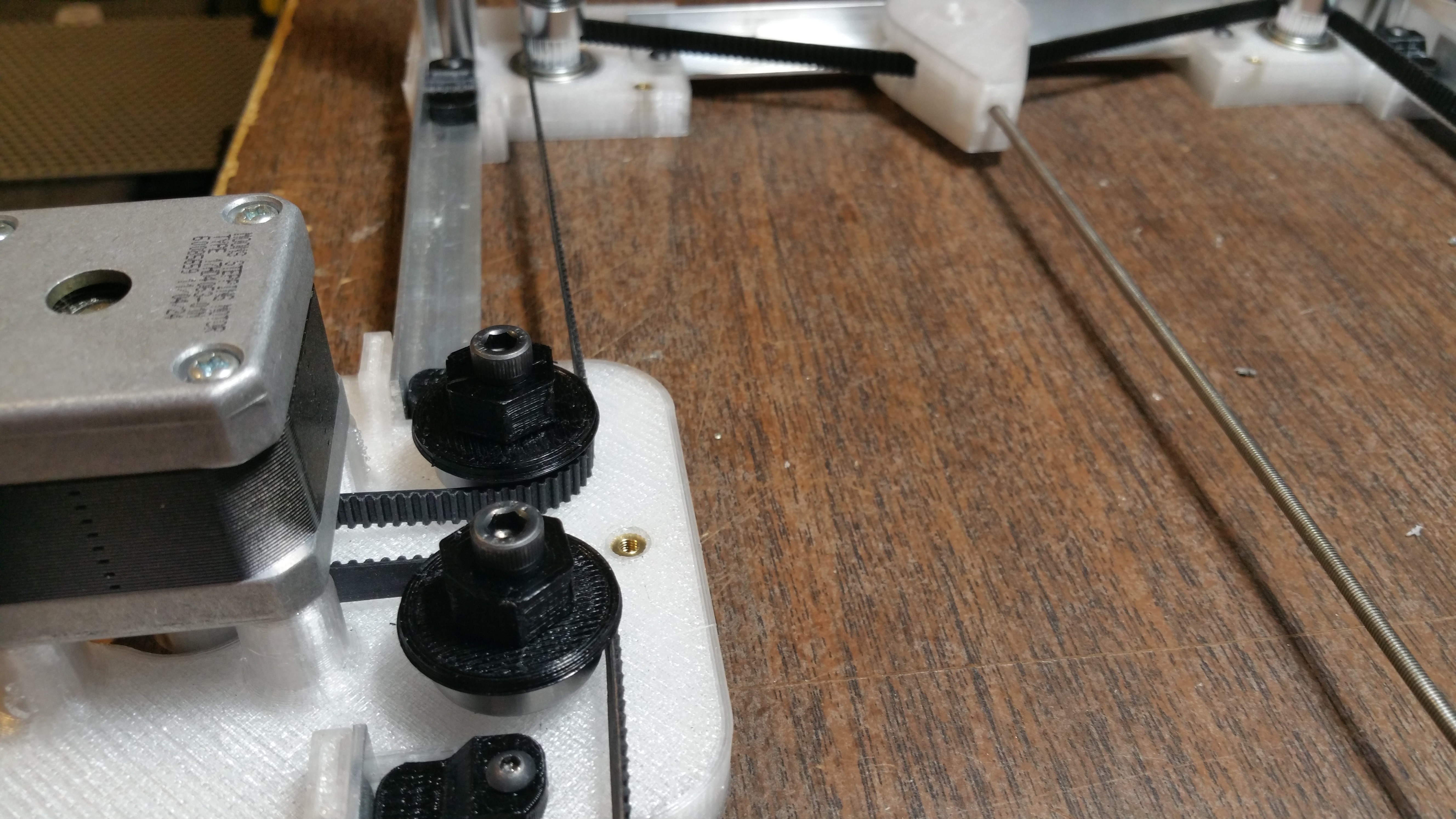
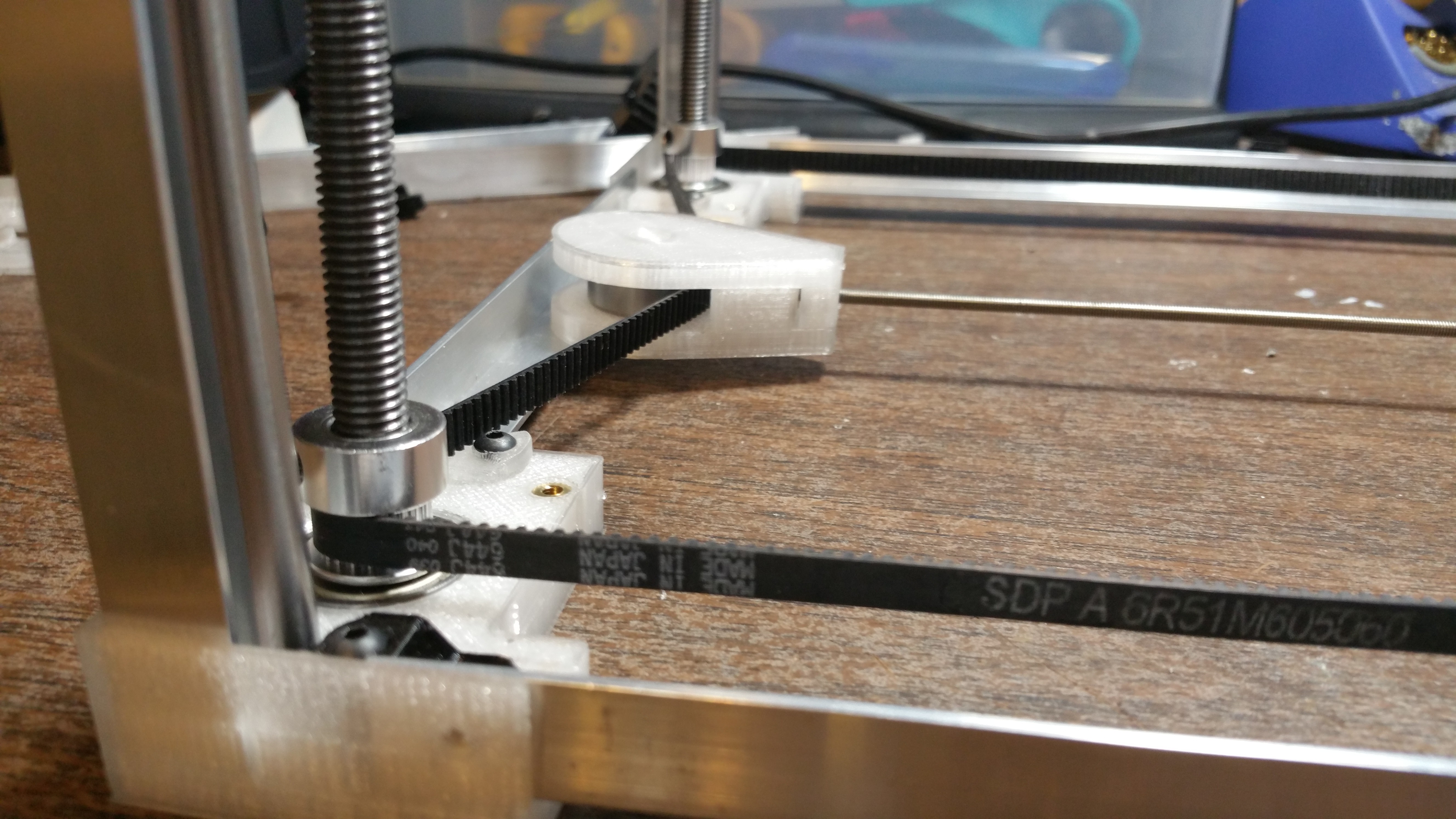
Originally the belt path was much simpler and it didn't use the tensioner assembly that you see in the middle. It was actually a perfect rectangular path that used the idler bearings near the motor and eccentric nuts to tension the belt. I found out though that there wasn't enough tooth engagement on the pulleys and the belt tended to slip. So this new tensioner assembly allows the belt to wrap around the pulleys more and mostly eliminates the slippage.
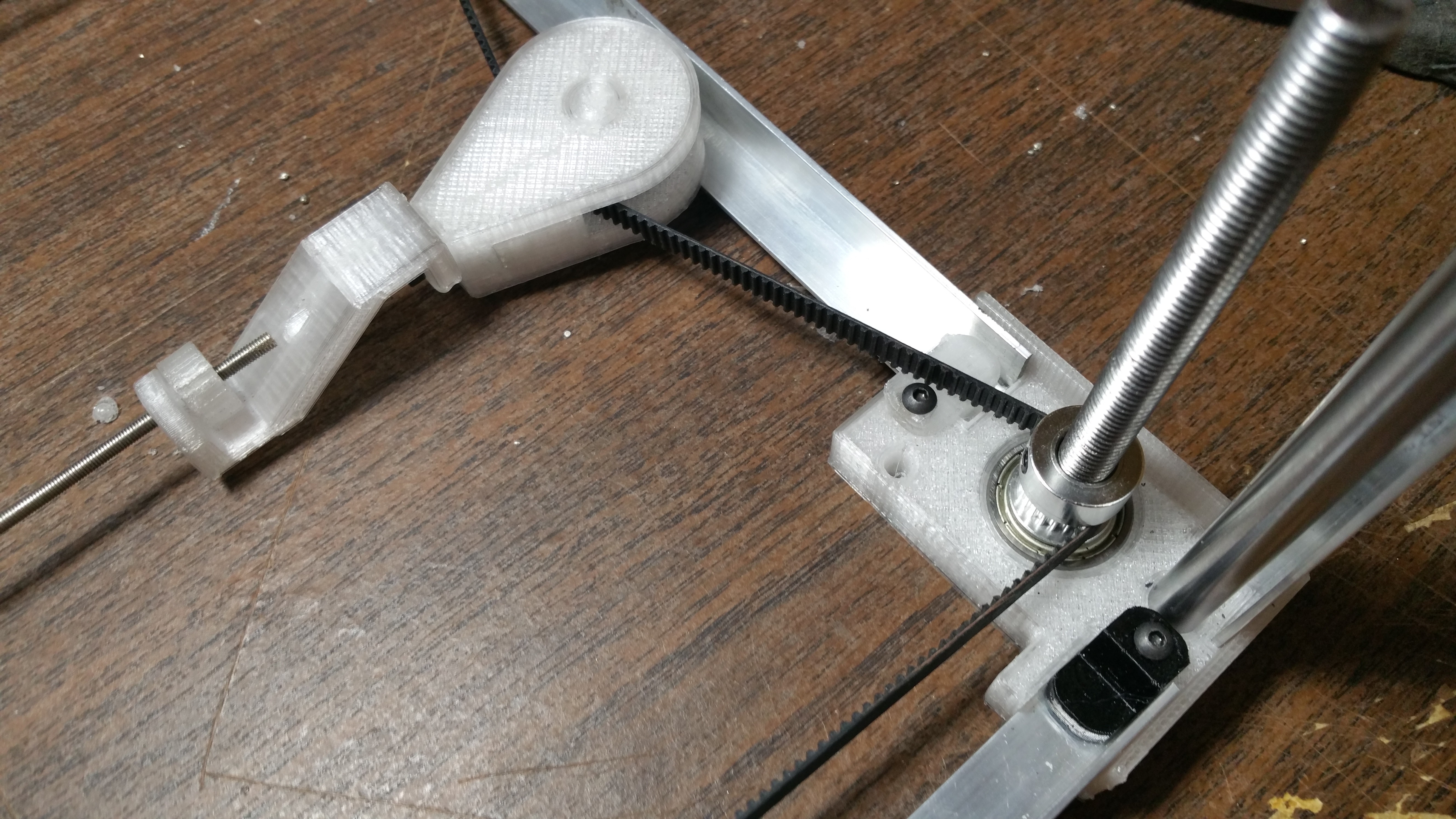
A closer look at the belt path


Once we install the bed, those threaded rods will straighten up.
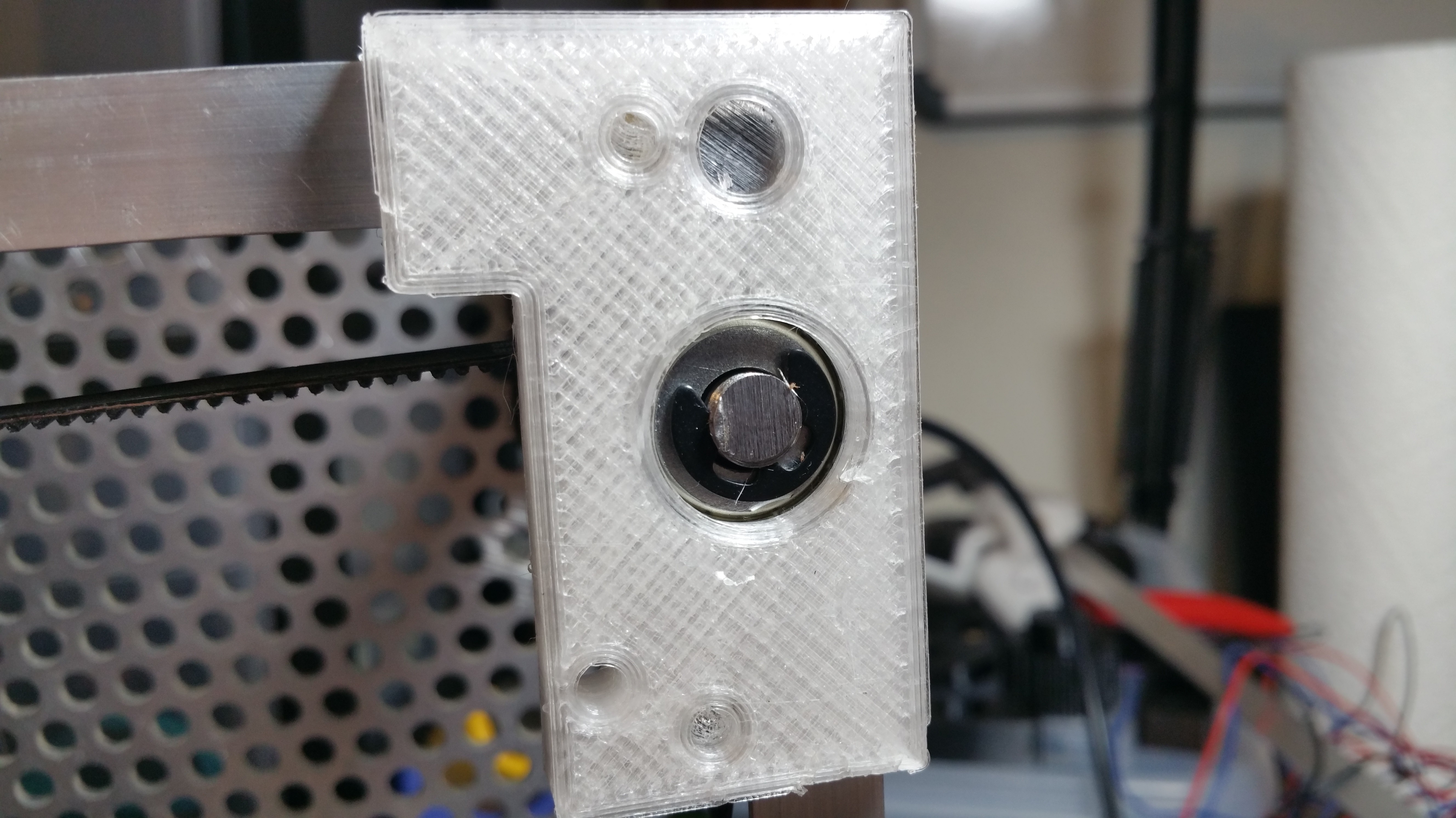 This is the underside of the bottom corners. This is where I installed the 7mm C clips to the threaded rod. This keeps the threaded rod from popping out of the bearings while the Z axis moves. Clearance may be an issue here, so you may need to add tiny feet in between these corners and the bottom of your machine if you find that the threaded rod is rubbing against the bottom of the K40.
Another thing to keep in mind is that if your threaded rods are wobbling too much, it may be because the c clip on the bottom of the bearing and the pulley on the top of the bearing are locking onto the bearing too tight. Since the c clip locks onto the helical threads, it means that it's not completely parallel to the bearing, thus causing the threaded rod to not sit completely vertical. To solve this, just allow a little bit of slop between the pulleys on the threaded rod, and the top of the 608 bearings.
If this was a precision machine I would do something else, but you will only be moving this Z axis once to adjust the material at the start of every job, so it's not a huge deal.
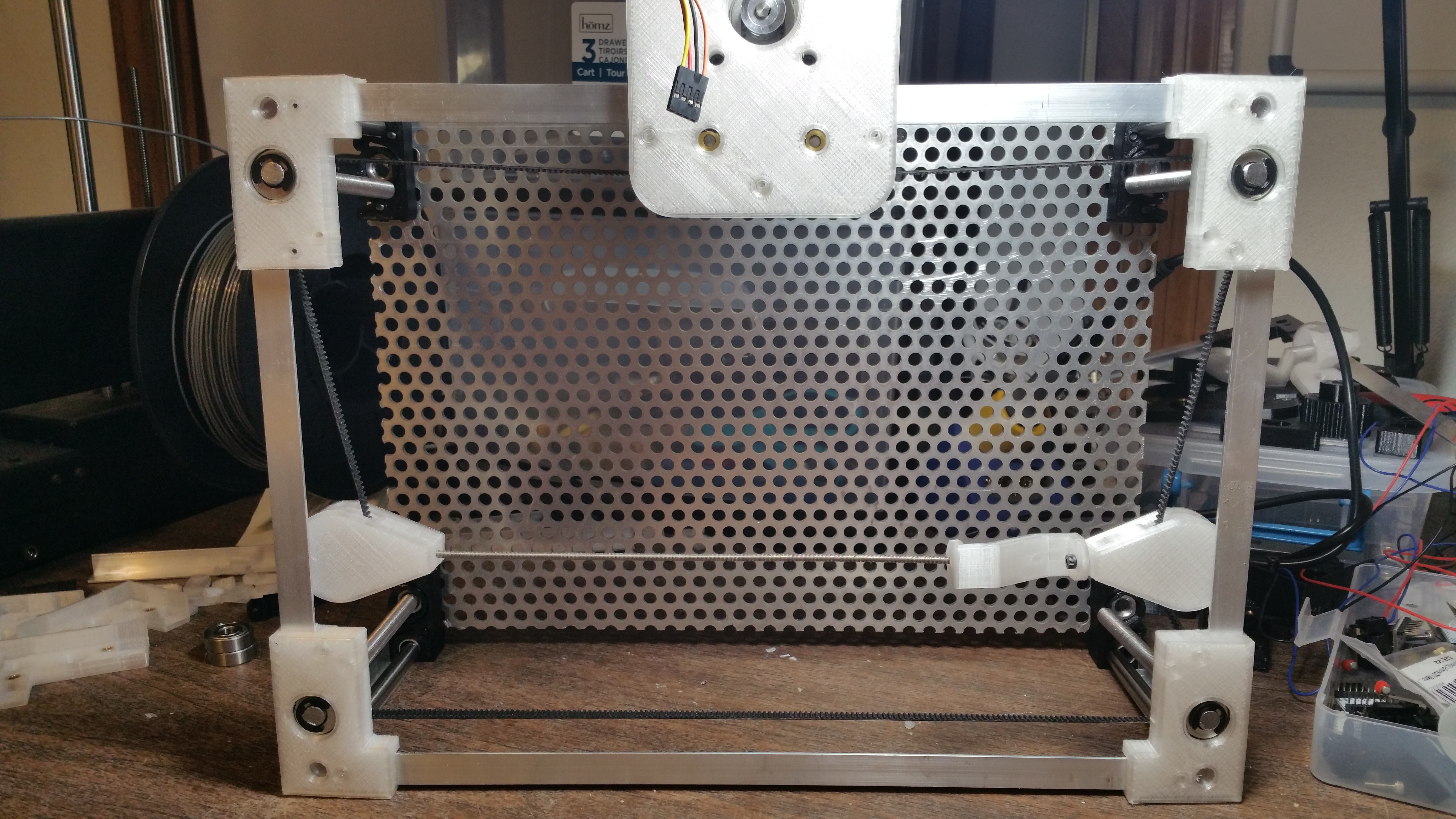
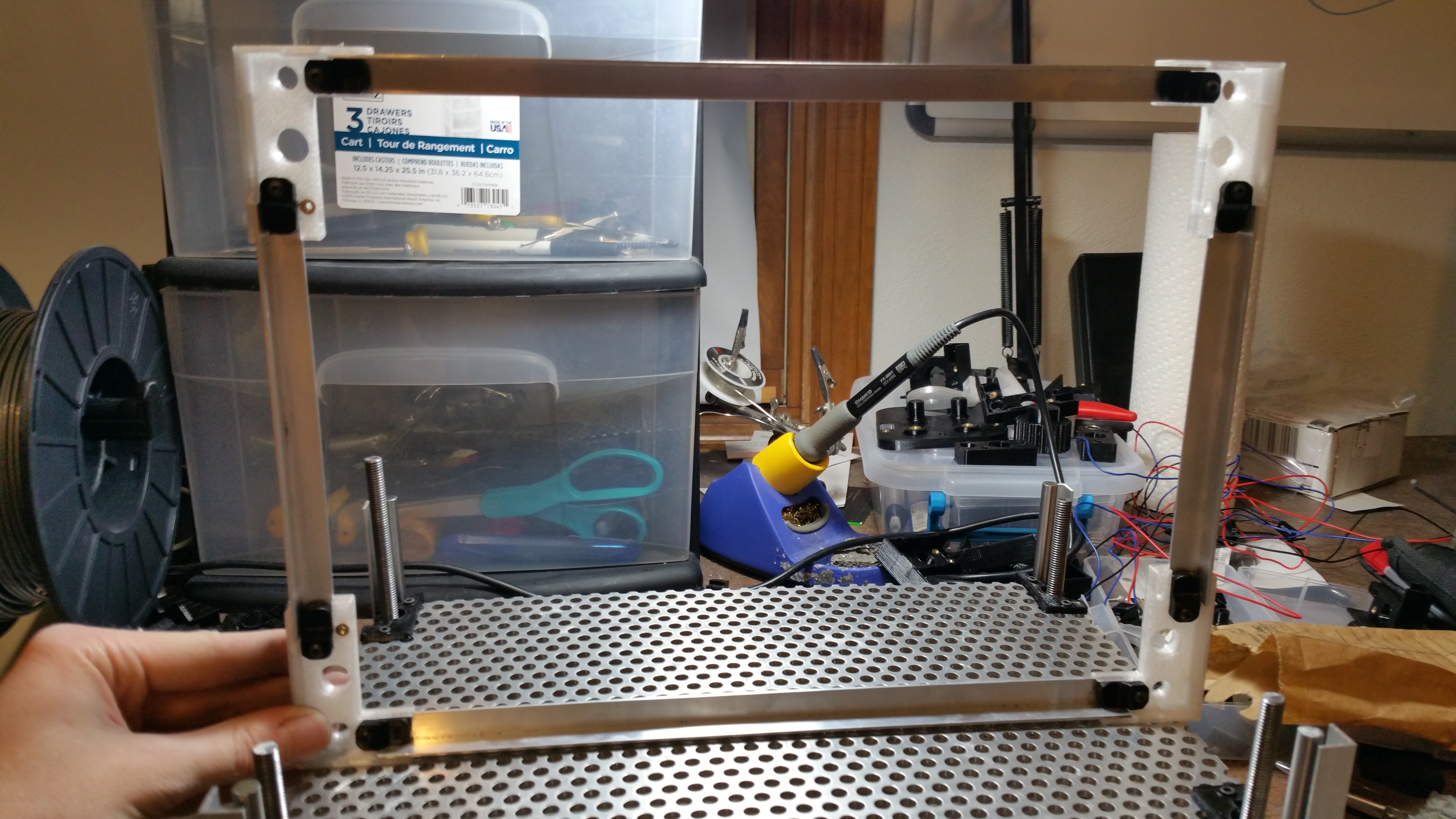 Top assembly. What isn't pictured here or in the photos of the bottom are the endstop mounts. They can be attached to any of the top or bottom corners.
 The top just pops on once the bottom is installed in the laser cutter. It may take a little bit of work to align all the corners and linear rods though, but again, it doesn't really add much strength to the overall design.
You may also notice that one of the threaded rods sticks out farther than the others. This is to attach a knob to allow you to adjust the bed manually. This may however cause the belt to slip and cause the bed to become unlevel/tram with the laser head, so make sure the tension is set properly before using it! (You might as well use the motor)
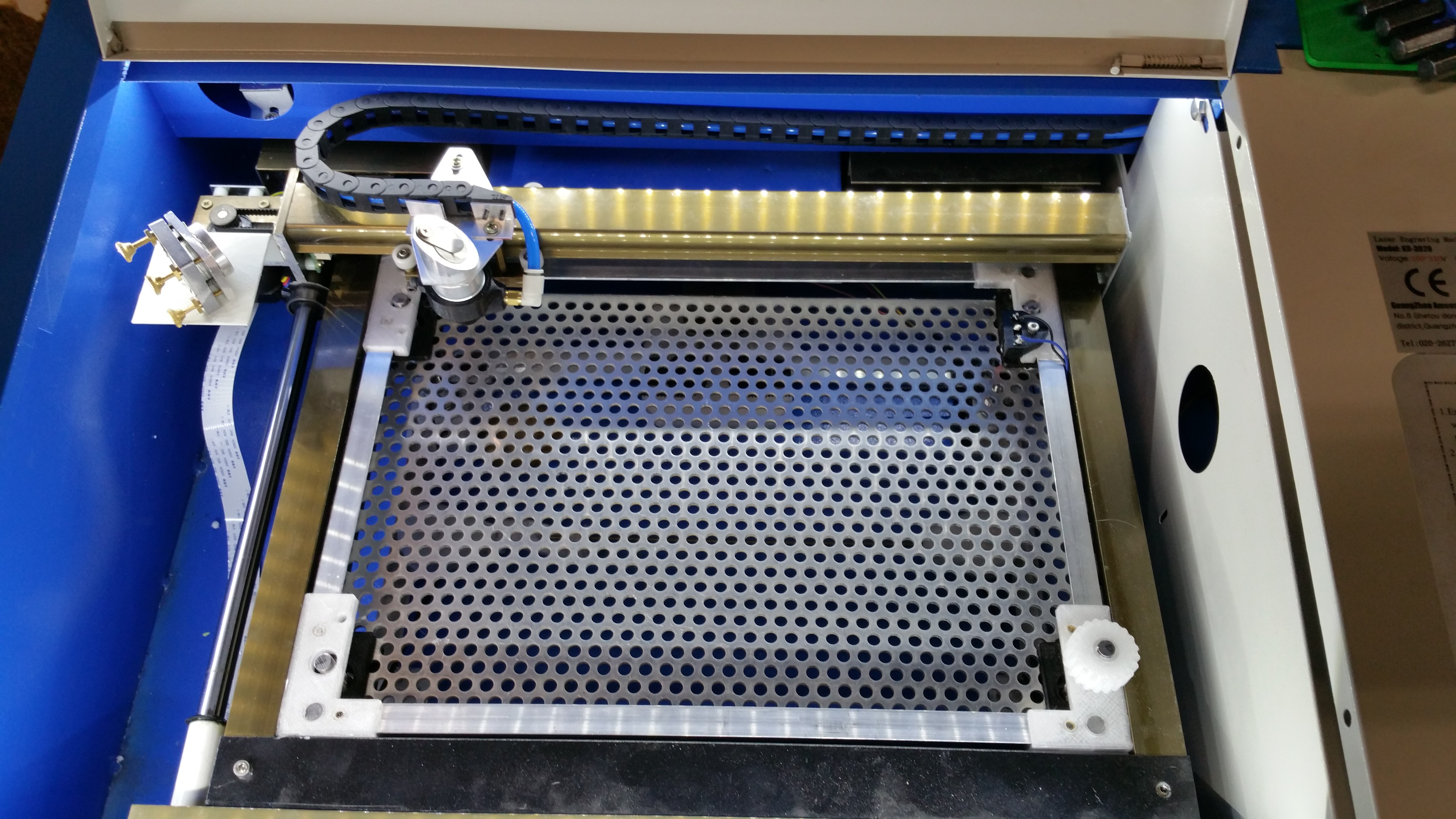 There it is installed in our K40 Laser Cutter at River City Labs. You can notice the adjustment knob in the bottom right, and the endstop holder in the top right corner. There are no mechanical connections between the z axis and the K40 itself. Again if this were a precision machine, I would do something different, but this just plops into place. It's a snug fit, but it works!
Also as a point of reference. The motor is located in the back (Y max). It's hard to tell from the photo. If there are clearance issues, then you may have to bend or cut away some of the sheet metal back there. There isn't anything critical there however, just be gentle and don't damage the laser tube in the process.
Also you may have to remove the exhaust vent that usually sits between the bed and the gantry. We cut ours down in our K40, and this Z axis was designed with that taken into account.
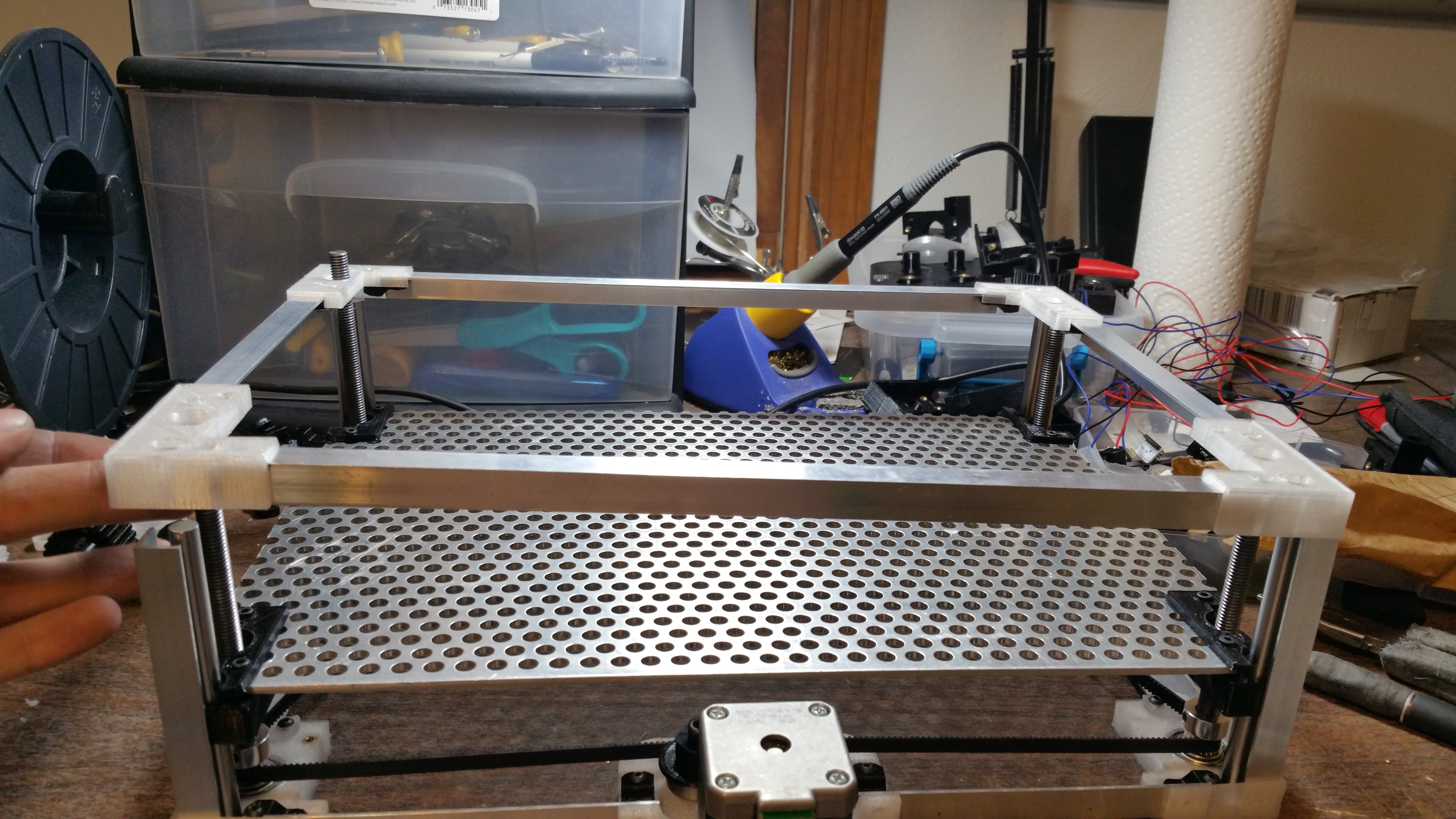
 Another angle.
I should also mention that this laser is not using the stock controller. Our K40 is actually running the Smoothie firmware (Details here) on a Cohesion 3d controller found here, and we are using Laserweb to control it.
Final Setup
Once you have the z axis installed there are a few other steps.
Leveling/ Tramming the bed
As with 3d printers, you need the bed to be parallel with the head of the laser cutter. If one of the corners is slightly lower than the others, then the beam will be slightly out of focus in that area, so it is critical to have them all at the same height.
The good news is that once we set all 4 corners and tighten the belt, then it should always stay tram/ level, assuming the belt doesn't slip on any of the pulleys.
I recommend tramming the bed before installing it into the K40! If the belt slips off one of the pulleys while it is installed then you will have to loosen the belt tensioner through the holes in the bed, and that can be tricky. (it is possible though)
The process
- Make sure everything is assembled except for the top frame
- Make sure the pulleys are tightened to the threaded rod in all 4 corners
- Loosen the tensioner mechanism (it may help to put the belt around the threaded rods instead of on the actual pulleys at this point)
- Move the bed to the top of the z axis until all 4 corners are flush with the top of the aluminum angle. You will have to rotate each threaded rod by hand until each corner is flush. We will basically be using the top of the aluminum angle in the corners to get a good reference.
(This should get us close enough for our purposes, but ideally you would want to use a dial guage attached to the laser head and measure it at all 4 corners. This should be good enough for our purposes though) - Once they are all pretty even, place the belt back onto the pulleys. This may make the pulleys move out of alignment a bit, but we will fix that next.
- Now we want to tighten the tensioner until there is just enough slack to allow the belt to slip on only one pulley at a time.
- Now we are going to get all of them flush with the top of the aluminum angle again by holding the belt firmly with one hand and turning the threaded rod with the other so that the belt slips over the pulleys teeth until it is at the correct height.
- Repeat with the other 3 corners
- Tighten the tensioner! This can be a bit tricky. If it's not tight enough, then the belt will slip on a pulley causing the bed to become un-tram/level. If it is too tight however, it may put too much stress on the motor (not enough to cause it to stall however) and it will pull more current than it needs too. You will have to find the right balance, and you may have to repeat the tramming/ leveling process a couple times if the belt slips. (also if you use the manual adjustment knob it will cause the belt to slip more than the motor does, so keep that in mind and ony use it if you really need to.)
- All done!......well sort of. How will we know if one of the pulleys slip once it is installed in the machine? Other than the beam being out of focus in one corner, another way that I came up with to see if any of the pulleys slipped is to use a paint marker and mark the tops of the threaded rods in a way that creates a pattern when they are all in sync. For our z axis, I simply created a pizza shape on the top of each threaded rod that would create a square shape when they are all in sync. You will want to do this as soon as you tram your bed for the first time. If you take the belt completely off though, then you will want to put on new markings.
Attaching the endstops
Depending on your setup, you may or may not have a way to use these. With our Cohesion 3d mini controller, it was very easy though.
Attaching the aluminum
This is more of a side note than it is a final step. You might notice that I added 3mm holes to where the aluminum angle meets the printed parts for all of the bottom pieces. This is simply to allow another, more rigid way to attach all the pieces together instead of using those clamps. The idea is to drill and tap the aluminum, and screw it together from the back. I never ended up doing this on the final version, but you may want to. If you tension the belt too much, it can cause the aluminum to bow out near the motor mount and become un-square. Again this Z axis doesn't need to be built like a tank for it to work. It just needs to move the material to the correct height.
Configuring Smoothie
If you are using smoothie to control your laser then you will need to enable the z axis and set the steps per mm. We are using a 200 step per rev, 1.8 degree motor with 1/16 microstepping and an M8 threaded rod which gives us 2560.00 steps per mm. If you are using a different motor or stepper controller then you will need to put in something else obviously.
You will also need to enable the endstops for the z axis. I would recommend using both the z max and z min just so that it doesn't destroy itself.
You may also have to adjust the build area dimensions.
As for the speed settings. I sat it to run at a max of 2mm/s. this isn't a 3d printer so we really don't need the speed. I also set the acceleration to 100mm/s which is likely overkill, but it works.
K40 modifications
There were a couple modifications that I had to make to the K40 itself to make this work.
I had to extend the endstop trigger on the x axis so that our air assist nozzle didn't hit the top of the z axis frame.
Power Supply!!!!!!
This one is important!
The K40 power supply only has enough power on the 24v line to power 2 motors! So with the added z axis motor we had to get a separate 24v power supply to run the motors. A 24v power supply is cheaper than the Laser Cutter power supply, so don't take the of risk burning it out, and just get a separate larger 24v power supply.
Done!
That's basically the extent of these instructions. The photos should help with most of the assembly, but unfortunately I can't go into much more detail. I hope someone finds this useful.
Here is a video of it in action. (This is a slightly outdated version with a cobbled together belt tensioner, but it is a decent demonstration)