I've started, using the links supplied, with getting an ATMega chip running on 8MHz with use of internal oscillator .Then I tested with the blink sketch to see if it worked.
Using a multimeter I checked if the solar panel was supplying voltage and I used a bench power supply to quickly supply an initial load of the supercapacitor. That is also best practice to minimize current leakage according to many websites. With the solar panel it takes a lot of time. ;-)
I'm now in the phase that I can blink an LED for minutes just using the supercap & solar configuration as shown.
Next steps are to implement power saving options as mentioned by the nice Helisoph and Nick Gammon website (URLs are delivered).
Low energy settings via Arduino sketches
Today experimented with low energy options based on suggestions from Nick Gammon's website about Atmegq328P power saving. Started directly with the ATMega 328P on breadboard with internal 8Mhz oscillator and performed some tests with power consumption using the 5V from USB PC via USB&serial converter:
- sketch A (empty sketch) 16 mA
- sketch B (sleep mode Power_Down) 375mA/ 0.35 uA
- sketch C (also brown out detection disabled) 0.35uA
- sketch D (also all analog pins defined as output with voltage LOW) 0.2uA
I didn't continue because these low current numbers are already impressive and I need to define what options are needed (analog or digital sensor, I2C or SPI?, time or event based interrupt to wake up the processor, etc.). Based on initial choice for IoT usage scenario I can continue to define settings and improve understanding of power needs.
Another solar panel
Another aspect is the solar panel, I had a small one with a Skottky diode to prevent reverse current to solar panel. I changed it for a GH165x135 solar panel where on the back of the panel I've soldered a Skottky diode 1N5819 (1N5817 is even better) and it works perfectly and gave even 6V output past the diode.
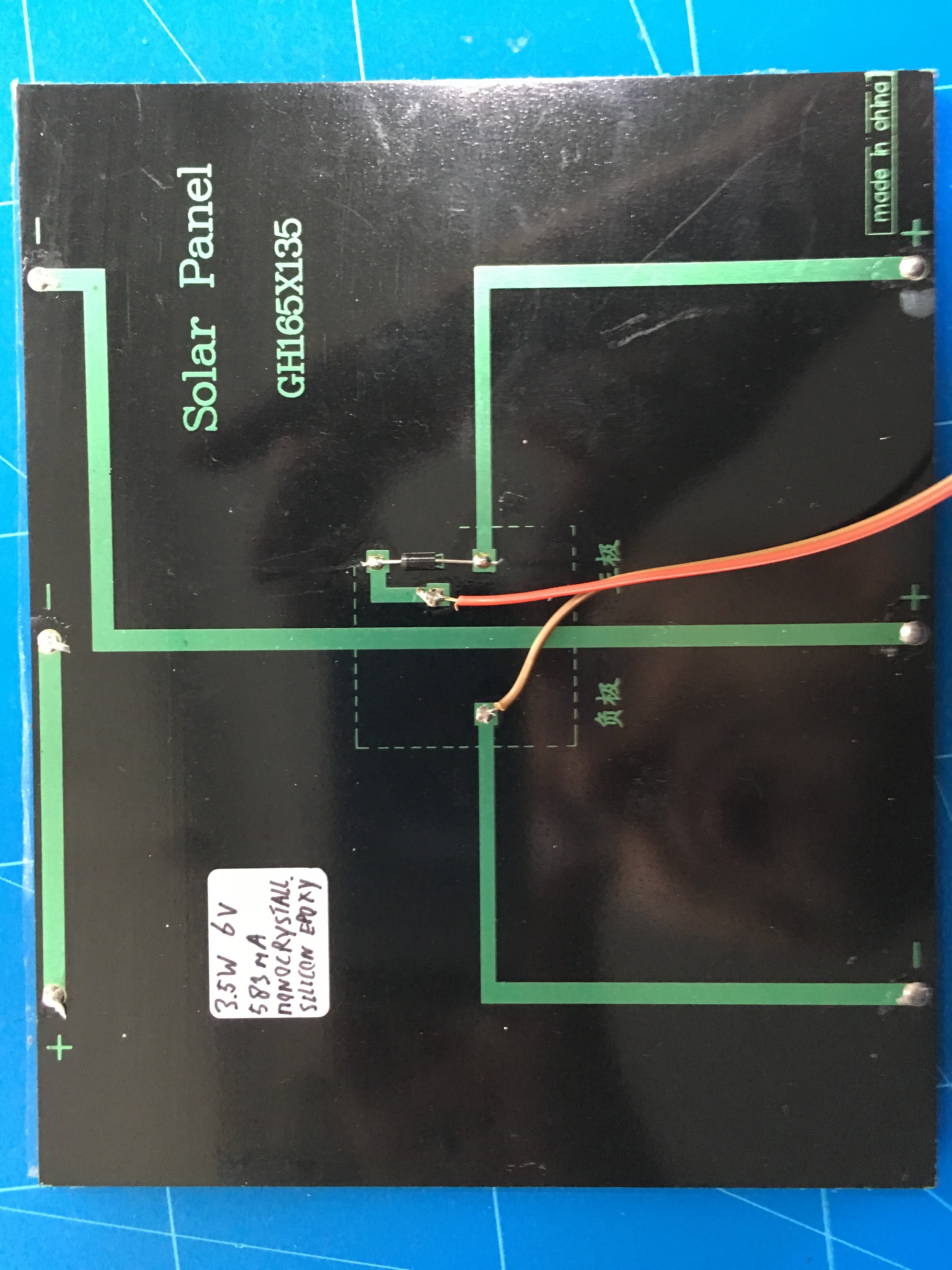
I was surprised because with the forward voltage of the diode I expected something around 5.5V which I preferred because I wanted to use it tot charge a 5.5V supercapacitor. and don't want to overcharge it.
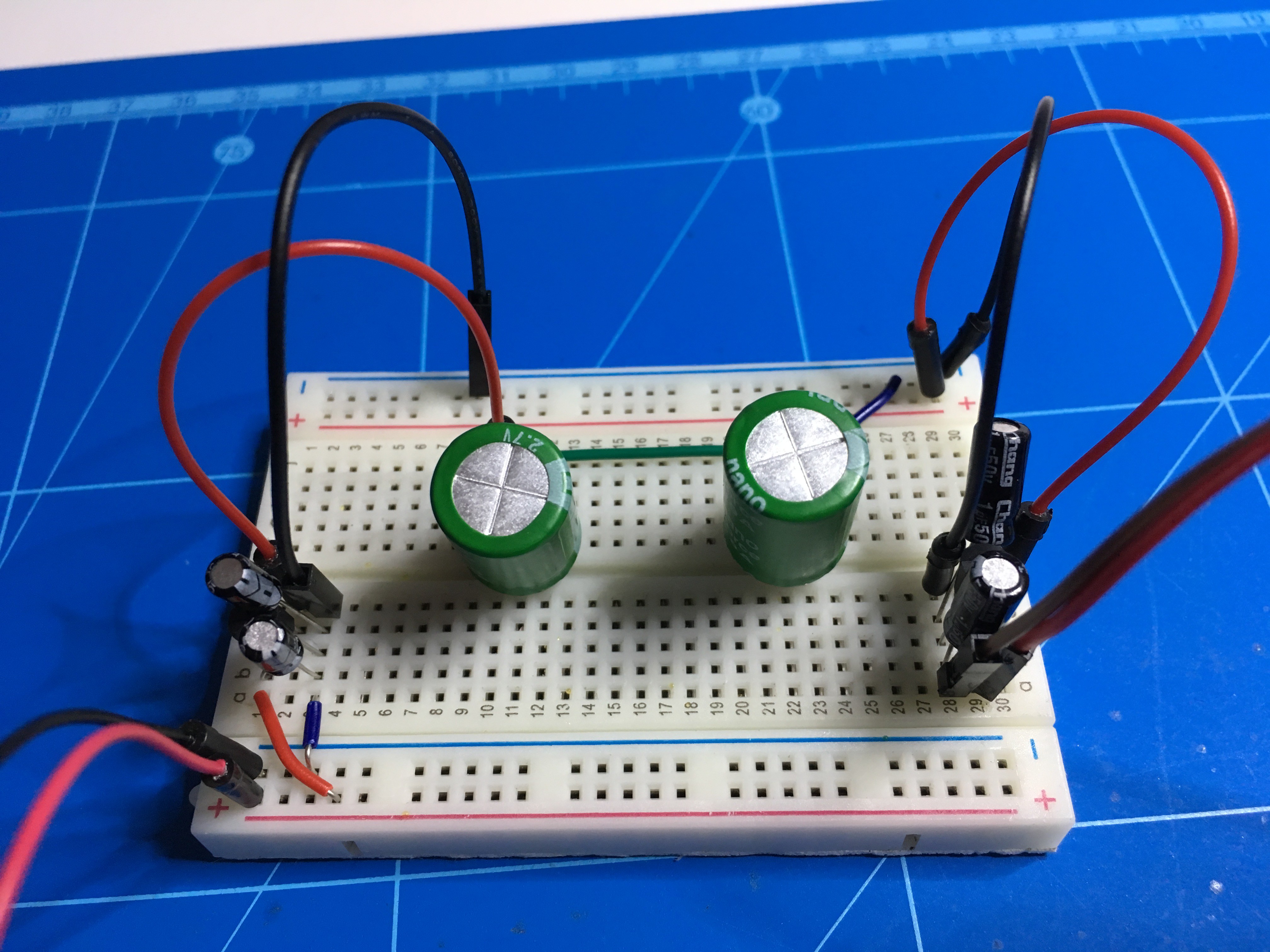
Change of plans with super caps
I've replaced the 5.5V 4F supercapacitor for two 2.7V 10F supercapacitors in series. This equals to 5.4V 5F. To avoid overcharging of the supercaps I saw some solutions using a zener diode to maximize for 5.1V but I didn't have that one. Then I used a MCP1700-5002E, low quiescent current LDO that delivers 5V for the two supercaps in parallel. Between the supercaps and the load I used the MCP1700-3302E to output about 3.3V. This is the voltage from my "power management" breadboard that I will use for my "IoT breadboard" with for now just the Atmega328P and LED for testing. In the next phase this will be replaced by sensors and a communications module. The solar power & storage solution can be improved but for now I'm happy with it.
At first I started with 2.7V 10F supercaps in parallel with the idea to run on ever lower voltages as a standard but that was to complex for me and a lot of sensor modules, FTDI USB serial converters that I have are aimed at 5V or 3.3V usage.
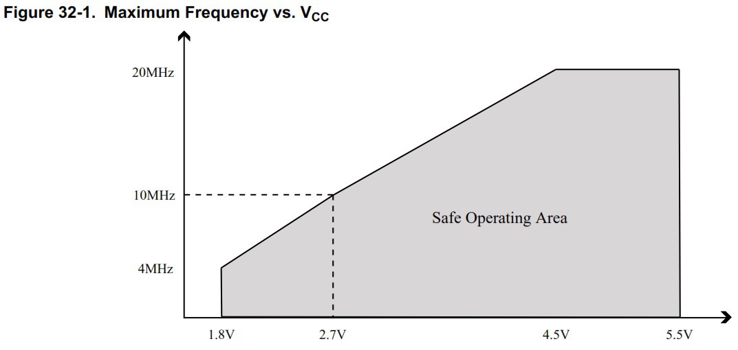
ATMega328P VCC versus frequency (from Atmel data sheet)
Adjusting fuse settings
I used the Eleccelerator fuse calculator to deternine the fuse settings for the 328P. The main change was enabling the brown out detection (BOD) for a minimum voltage of 1.8V. I know that enabling BOD increases the current use but I don't want to have an instable 328P that can't recover.
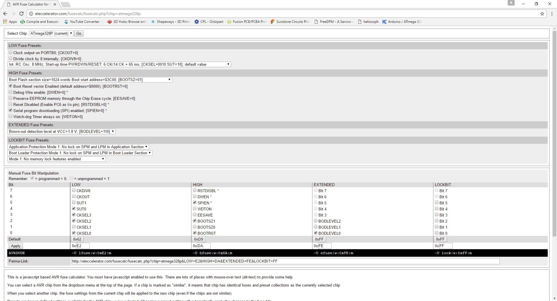
Using Arduino ISP as programmer, I used AVRDude via the command line:
- avrdude -P COM16 -b 19200 -c avrisp -p m328p -v (to check settings)
- avrdude -P COM16 -b 19200 -c avrisp -p m328p -U efuse:w:0xFE:m (to enable BOD with 1.8V)
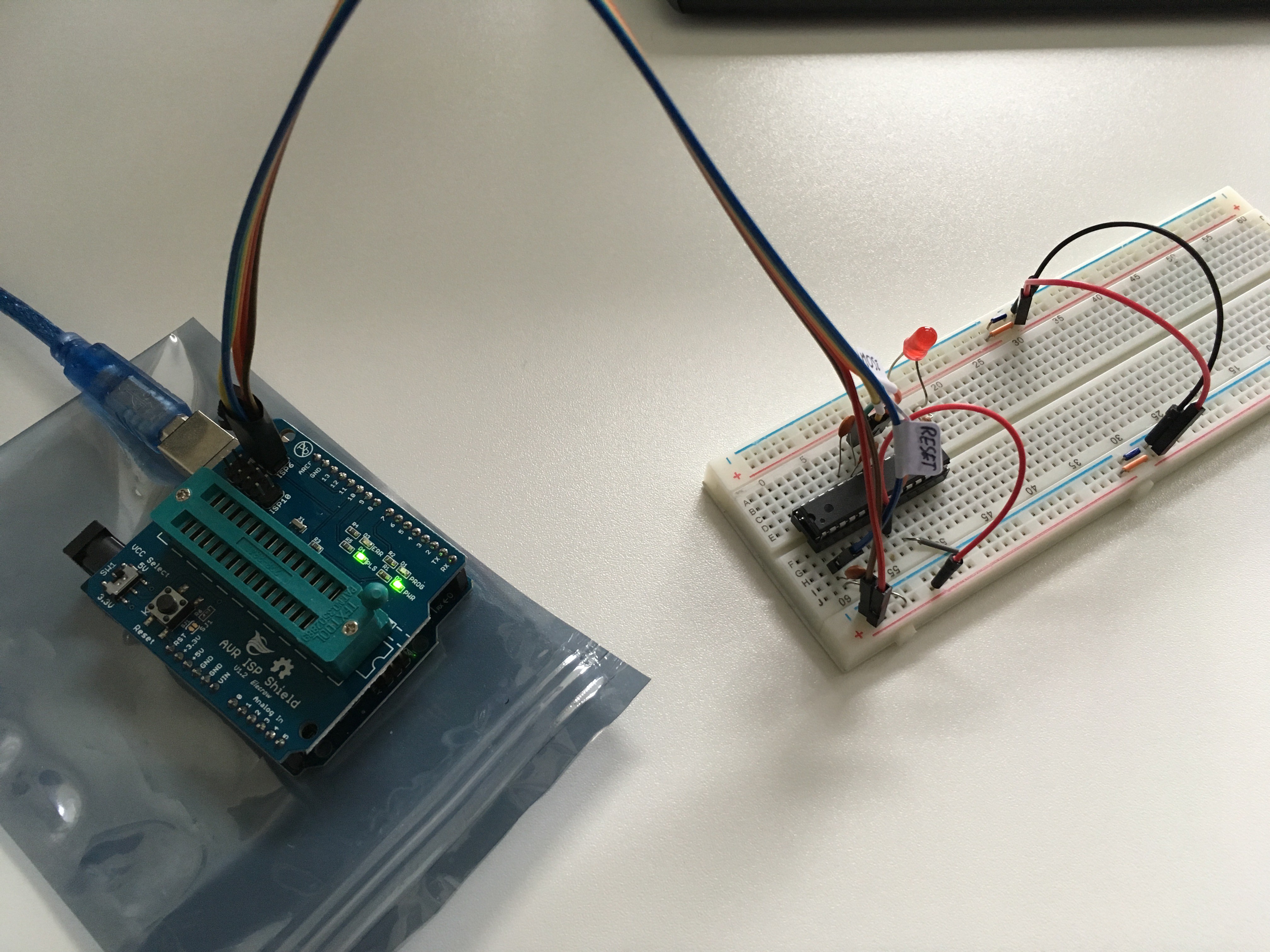
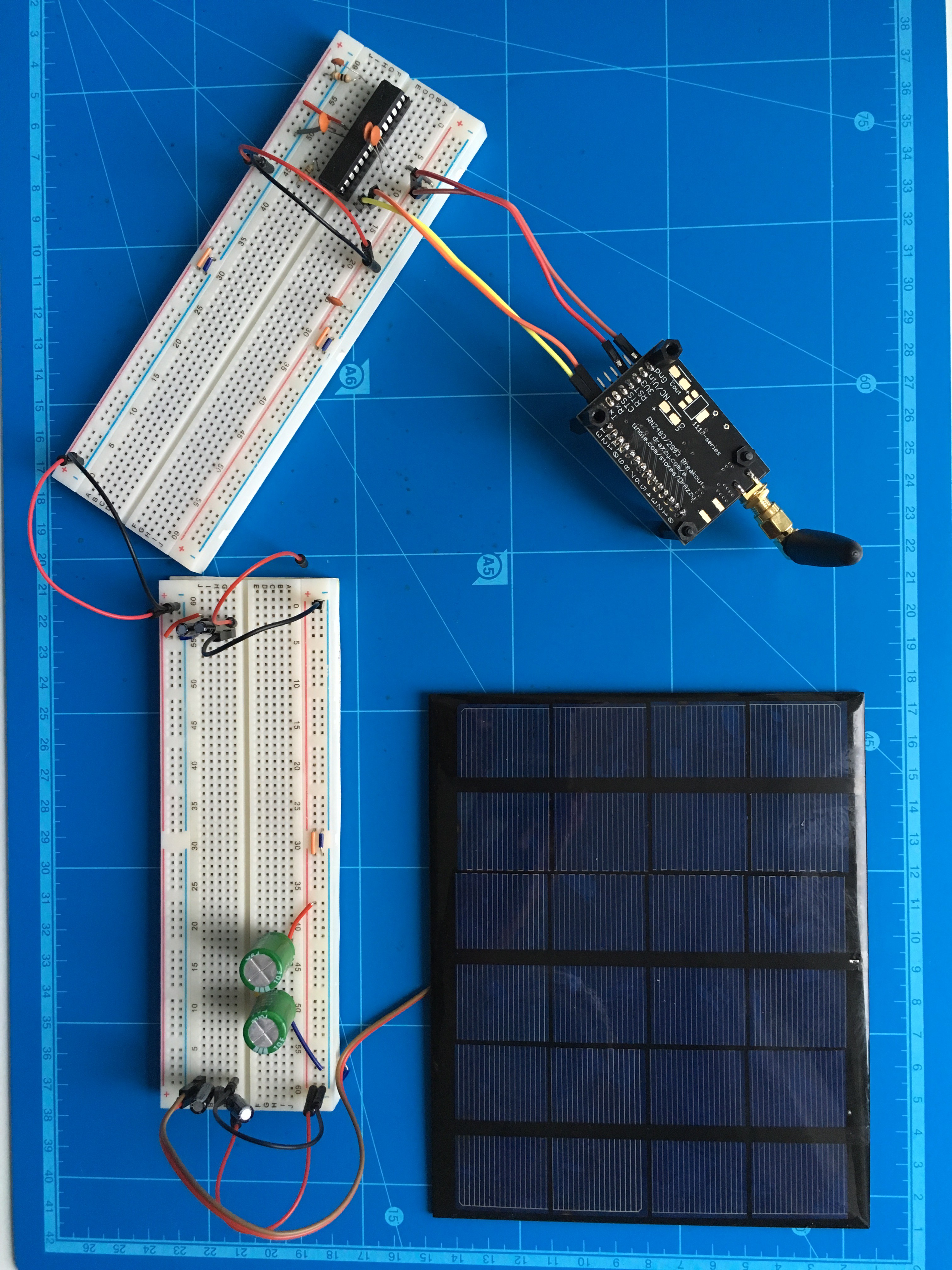
My hardware setting so far, still without LoRa transceiver
Below the overview of the hardware used based on some optimizations. The larger breadboard is handy for the I2C sensor(s) that I want to add.
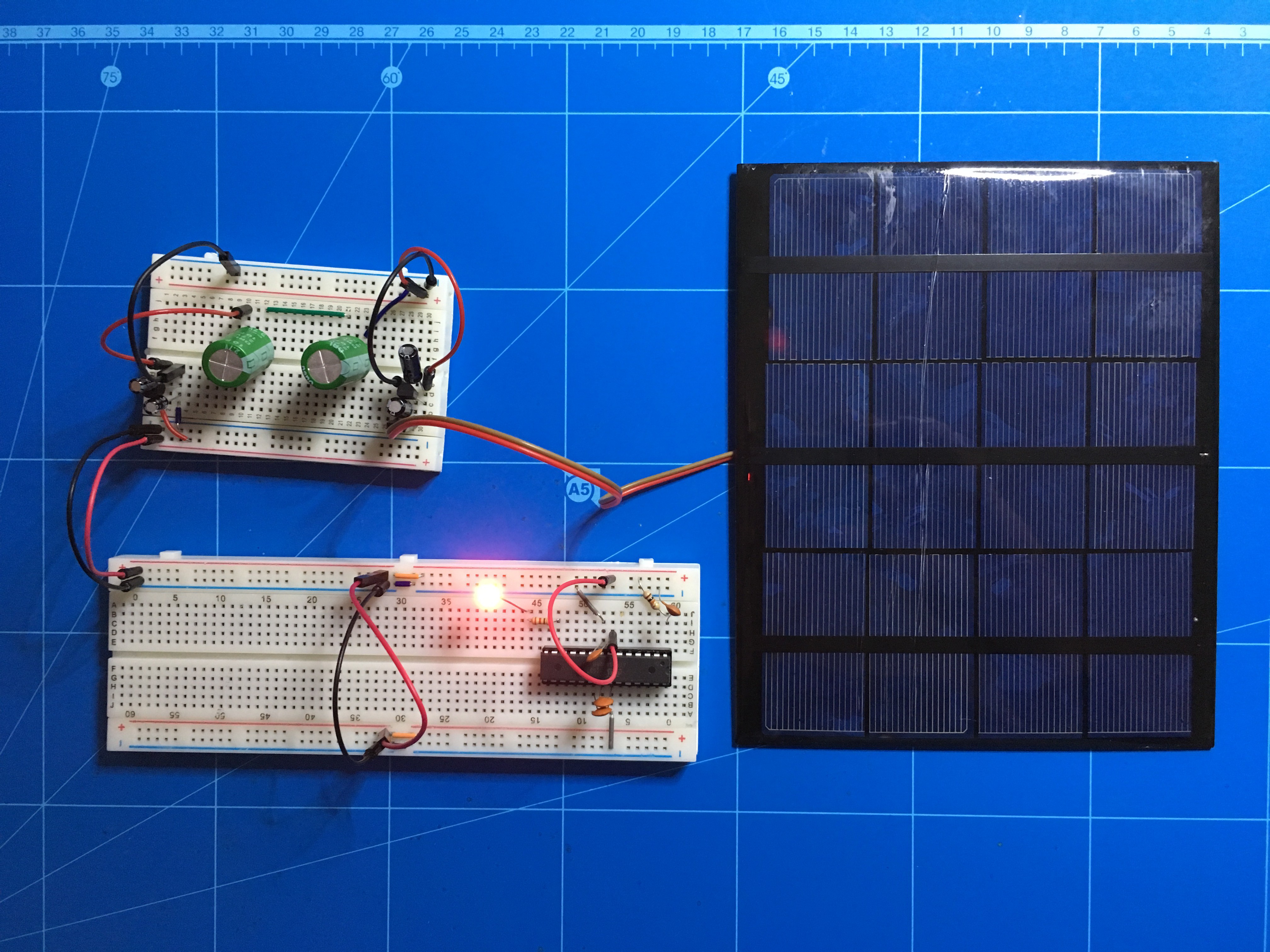
With just a simple blink sketch without any optimization settings for low energy usage and sleep as tested before I can already blink the LEDs for minutes.
Attached a video to show the setting and the blinking LED.Test with supercaps and timer based sleep
I've use a sketch from the website of Donal Morrissey for a quick test with of the usability of the supercaps as sole energy source for the times when there is energy from the solar panels.
- It uses SLEEP_MODE_IDLE (the worst sleep mode but probably needed for the timer based interrupt used, in the Gammon website he compares the sleep modes and this one uses 15mA in his situation compared to 0.36mA in SLEEP_MODE_PWR_DOWN, a major difference)
- About every 8 seconds the LED is turned on in "normal" situation and then it goes to sleep for 8 seconds
My results without the solar panel and only the supercaps is 65 minutes uptime:
- About 488 times a current use of 7.30mA with the LED on for 8 seconds
- The other 50% is the current use around 1.40mA in sleep mode
This is very promising to work on:
- The LED will be replaced by low energy I2C sensor(s) that only need to run for microseconds in stead of the 8 seconds
- I'm aiming at using SLEEP_MODE_PWR_DOWN which can be about 40 times more energy efficient looking at other test results
- The sleep period can be extended, one major negative impact can come from the RN2438 module for the LoraWan communication in order to send the sensor data
// Sketch for testing sleep mode with wake up on timer
// Source from Donal Morrissey - 2011
// http://donalmorrissey.blogspot.nl/2011/11/sleeping-arduino-part-4-wake-up-via.html

#include <avr/sleep.h>
#include <avr/power.h>

#define LED_PIN (7)

volatile int f_timer=0;
ISR(TIMER1_OVF_vect)  //Timer1 Overflow interrupt
{
  /* set the flag. */
   if(f_timer == 0)
   {
     f_timer = 1;
   }
}

void enterSleep(void)
{
  set_sleep_mode(SLEEP_MODE_IDLE); // This is not the most efficient sleep mode
  sleep_enable();

  // Disable all of the unused peripherals during sleep to reduce power consumption
  power_adc_disable();
  power_spi_disable();
  power_timer0_disable();
  power_timer2_disable();
  power_twi_disable();

  sleep_mode(); //Enter sleep mode
  sleep_disable(); // First thing to do is disable sleep
  power_all_enable();
}

void setup()
{
  Serial.begin(9600);
  pinMode(LED_PIN, OUTPUT);

  // Configure the timer
  TCCR1A = 0x00; //Normal timer operation
  TCNT1=0x0000; //Clear the timer counter register
  TCCR1B = 0x05; //Configure prescaler for 1:1024, giving a timeout of about 8 seconds with the 8MHz 328P on breadboard
  TIMSK1=0x01; //Enable the timer overlow interrupt
}

void loop()
{
  if(f_timer==1)
  {
    f_timer = 0;
    digitalWrite(LED_PIN, !digitalRead(LED_PIN)); //Toggle the LED
    enterSleep(); //Re-enter sleep mode
  }
}
Connecting to the LoRaWAN network of KPN
I've used an certified Microchip RN2483 LoRa tranceiver for my project to connect to a LoRaWAN network. In the Netherlands we have the telecom provider KPN that offers a country wide LoRaWAN and The Things Network.
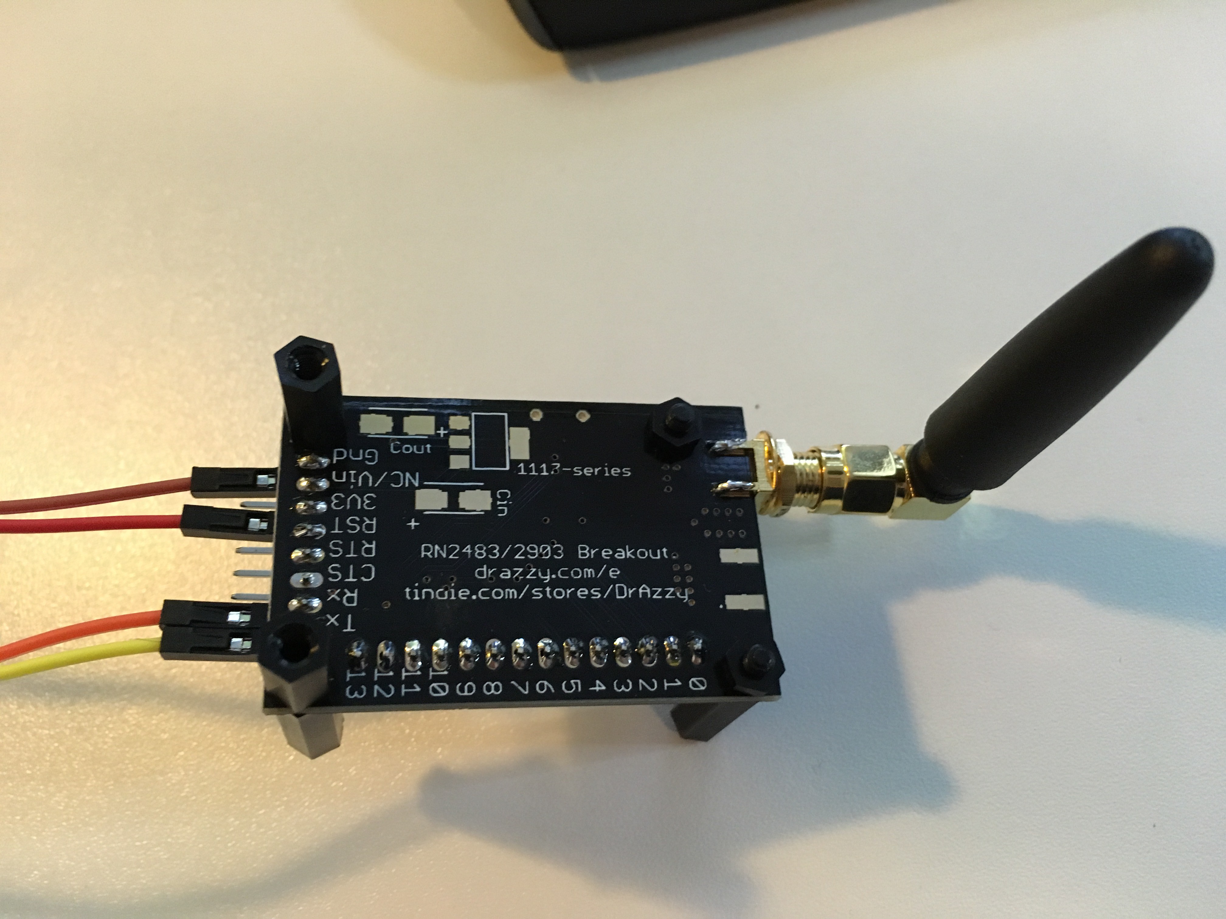
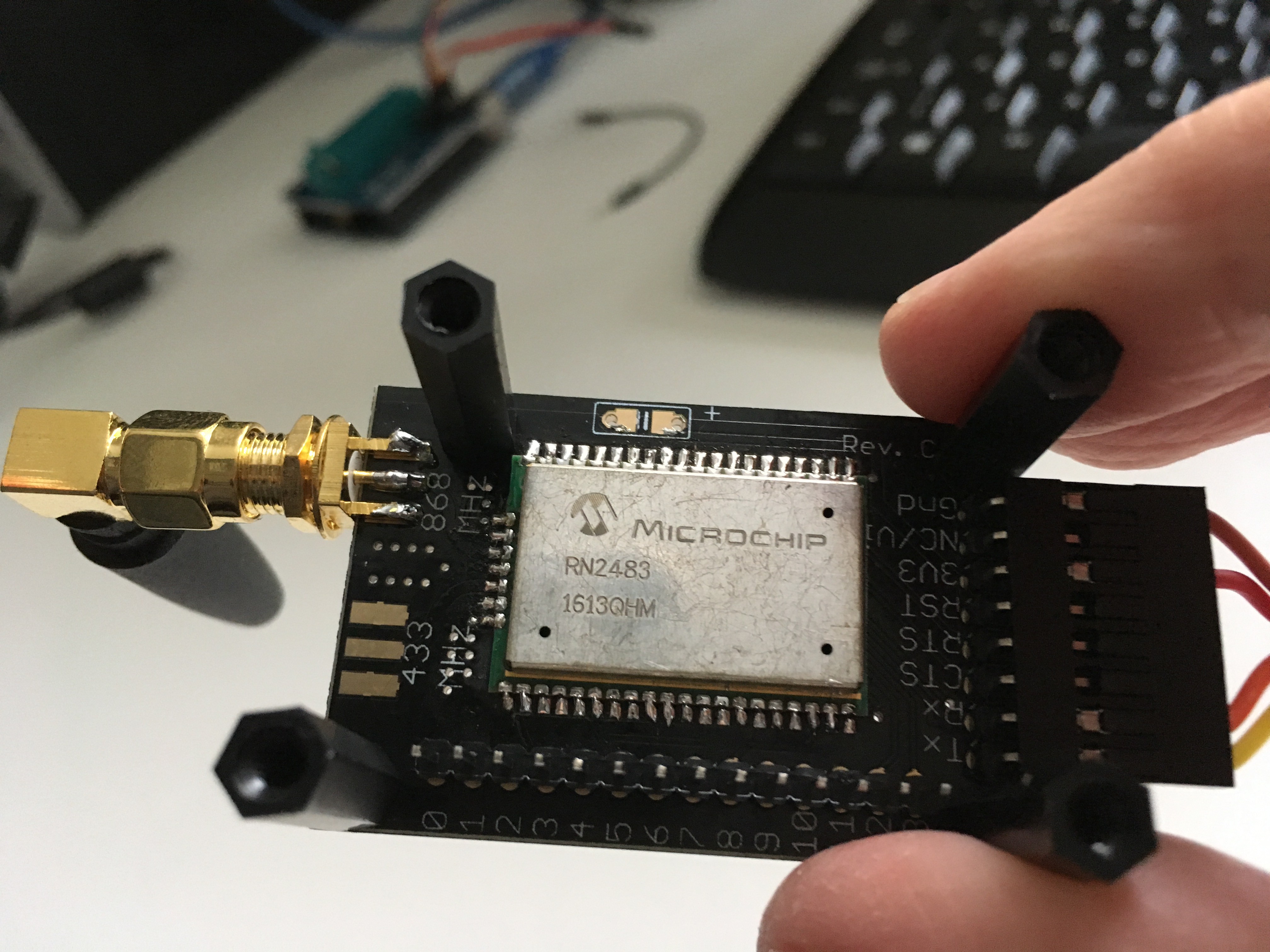
The RN2483 (PIC18F46K22 inside) has an easy serial interface to enter system, MAC and radio commands. The IC is not the easiest to solder and hard to work with on a breadboard. I've used a nice PCB from Azzy's Electronics shop at Tindie.com to solder the IC on and to expose the pins.
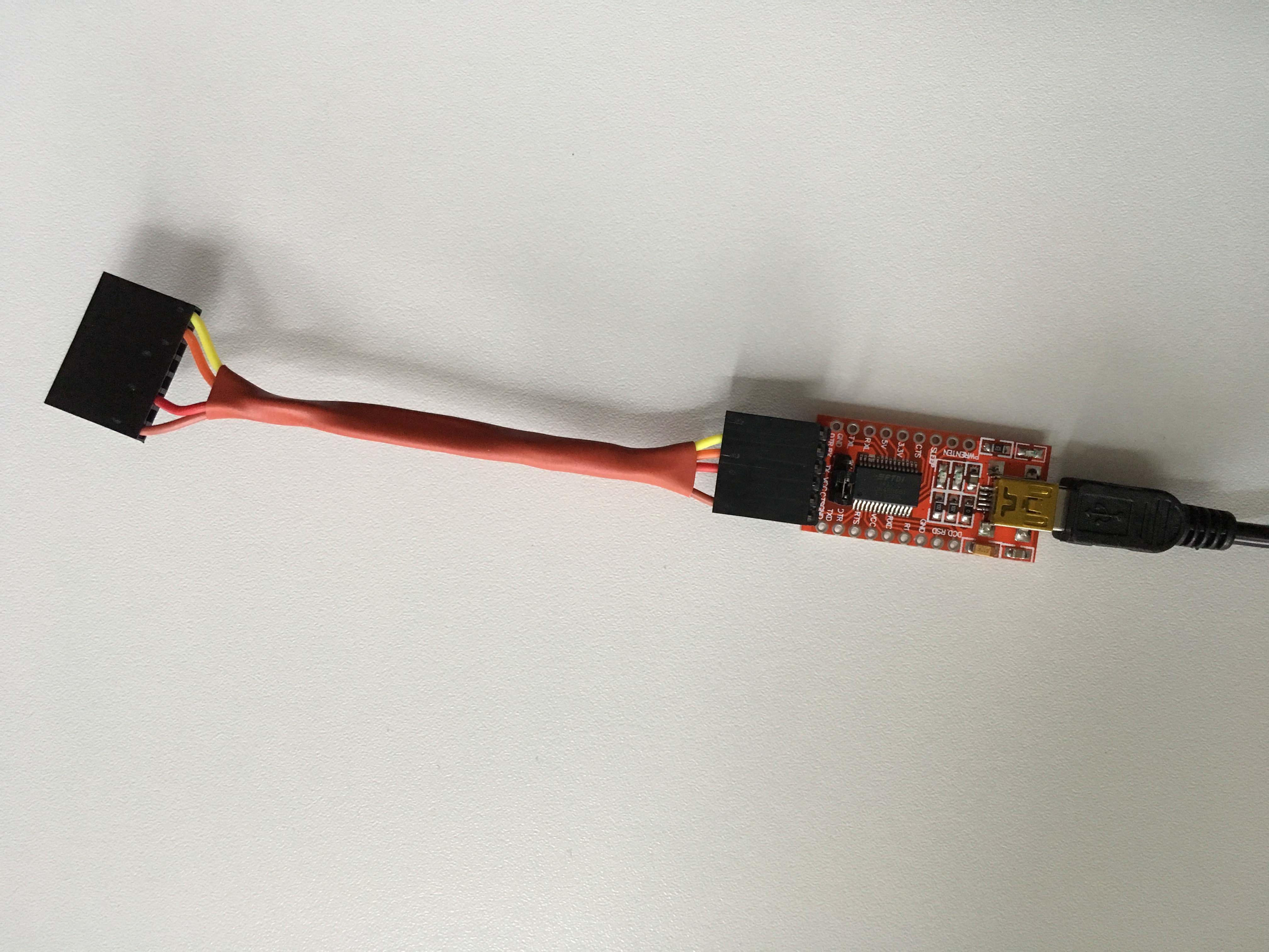
Inspired by Andreas Spiess video "Five Tricks for working with Dupont wires", I made a nice cable to connect the 3.3V to the USB of my PC via a FTDI-TTL converter. This avoids the continuous challenge to make the right connections. ;-)
Using a terminal session I've entered all ABP & network related configuration settings and saved them to the EEPROM of the RN2483. This minimizes the Arduino sketch with only the serial commands for communication with the LoRaWAN network. So also no library needed other than SoftSerial. My initial test code is based on insights from Rudi Niemeijer blog (Dutch) that also experimented with the Attiny and RN2483.
So after some tweaking, discovering a bad cable with major impact, initial tests with power from PC and bench power supply, I got the following assembly.
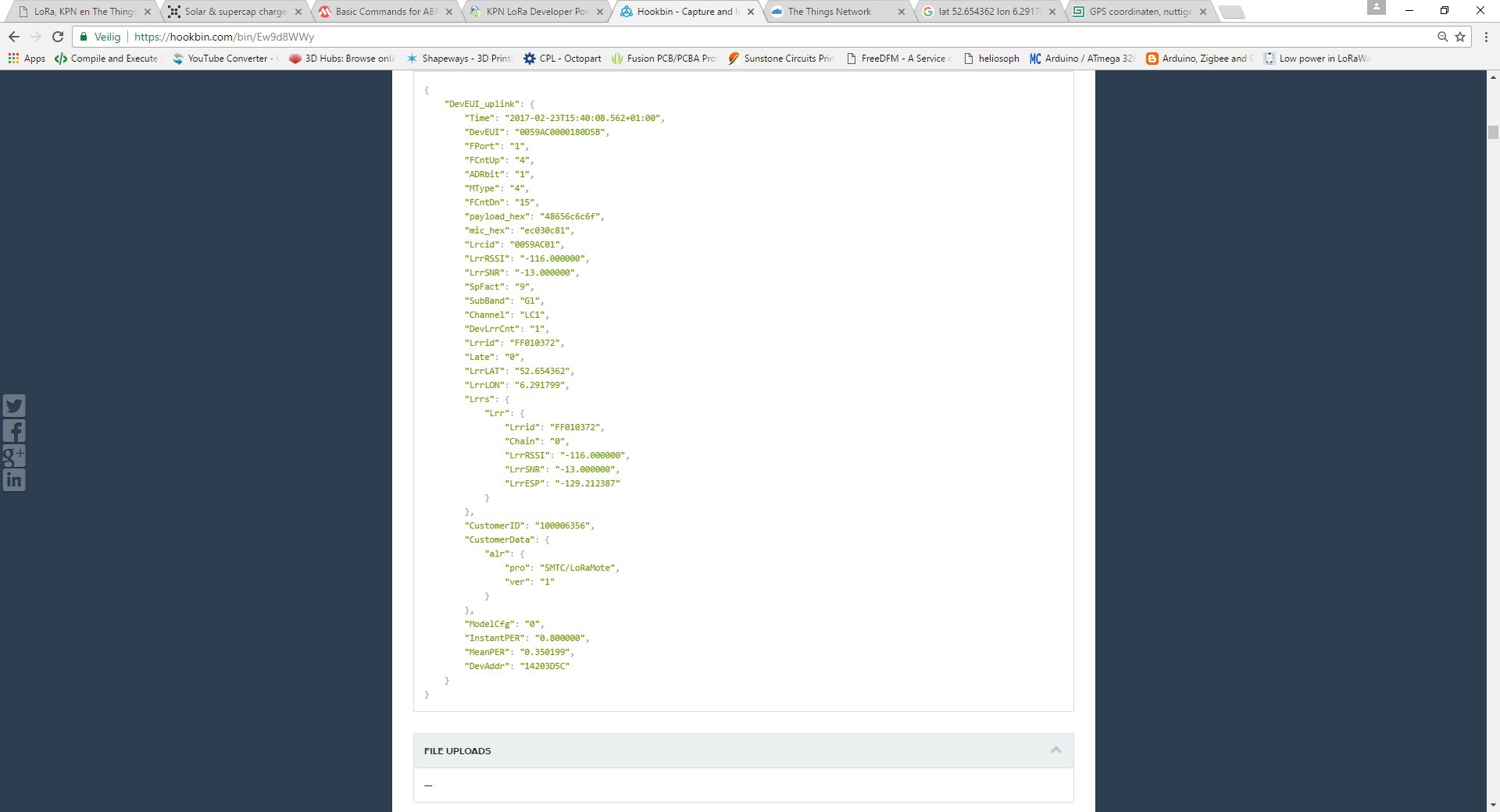
And....I worked and I've communicated some messages via the LoRaWAN network to the Internet with power from the supercaps! ;-) With the KPN development environment the data has to be delivered to a HTTPS server and I used Hookbin. And one of the messages received there is shown below.
My initial thoughts were to use the sleep timer of the RN2483 module. This timer can count for days and after sleep it transmits something on the serial bus. This could be used as trigger for the 328P that could be put into deep sleep mode till the LoRa module awakes. My problem is that I don't have stable serial communication with the softserial library on 57600 baud in my hardware setting with the 328P running on internal oscillator with 8MHz. Sometimes it works and sometimes it doesn't.
You read a lot about electronics and that you should have fun with trying the find errors. Well based on that definition I could say that I've entered an area with lots of fun. ;-
I made a test setting to test the serial communication and possible use of timer trigger from RN2483. Used a logic analyzer to inspect serial traffic between 328P and RN2483 reveiled strange behavior. It randomly seems to work but still no clarity. Looks like the ports are pulled high if there is no communication. Also sometimes errors with stop bits.
I did retesting with another RN2483 and even with a Pro Mini 3.3V 8MHz in stead of my 328P on breadboard but still no solid results.
After some searching on the web I read a lot about stability errors with softserial and looked for options with the use of hardware serial. Now I found the Atmega328PB that comes with 2 hardware based USARTs. This could be a viable option for my use. It comes in a TQFP package that isn't breadboard friendly so I will try to solder it on a pcb to I can continue my project. For now I will wait till the parts arrive.
Elektor R4 Uno with 328PB as platform for coding & initial testing
I'm still waiting for the 328PB ICs to arrive but I realized that I already have an Elektor Uno R4 that utilizes the Atmega328PB IC.
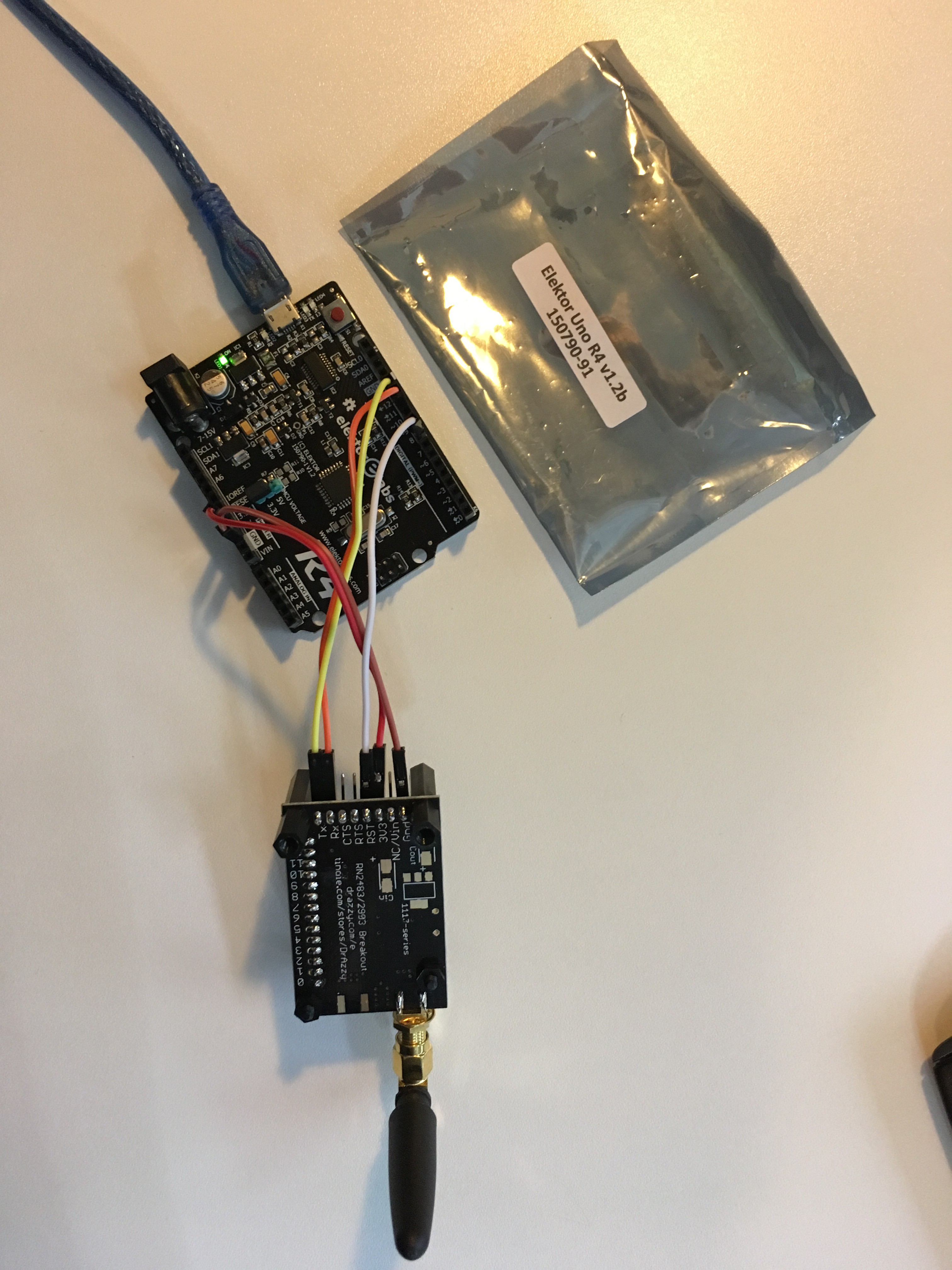
It can handle 5V and 3.3V. By removing the resistor R7 and placing the jumper to the 3.3V position at JP1 you get 3.3V as default board voltage and also on the GPIO pins. This is perfect for my purpose while I'm using 3.3V components. This Uno like board can be used for developing the necessary software. If this works, then I can transfer the solution to a 328PB IC on breadboard to test the energy usage and solution together with the supercaps and solar panel. Using the R4 Uno I still noticed strange behavior and searching the web I learned that it is necessary to reset the RN2483 board. Below the Arduino code I used for communicating with the RN2483 and that is useful for reading and storing LoRa communication settings on the board.
void setup() {
  // initialize both serial ports:
  Serial.begin(57600);
  Serial1.begin(57600);
  pinMode(11, OUTPUT); // MCU TX
  pinMode(12, INPUT); // MCU RX
  pinMode(1, OUTPUT); // RN2483 TX
  pinMode(0, INPUT); // RN2483 RX

// Reset of RN2483
  pinMode(8, OUTPUT); // RN2483 Reset
  digitalWrite(8, LOW);
  delay(500);
  digitalWrite(8, HIGH);
  delay(1000);
}

void loop() {
  // read from port 1, send to port 0:
  if (Serial1.available()) {
    int inByte = Serial1.read();
    Serial.write(inByte);
  }

  // read from port 0, send to port 1:
  if (Serial.available()) {
    int inByte = Serial.read();
    Serial1.write(inByte);
  }
}
Coming steps I foresee
- replace 328P with 328PB that comes with 2 HW USARTs and hopefully solves my problem
- use of own ESP-8266 & RFM95 based LoRa gateway (if delivery of TTN gateway is further delayed)
- optimize power savings options (Arduino sketch) based on IoT usage scenario, probably all digital so powering off ADC, analog related MCU functions, etc.
- add an interesting sensor, likely an I2C sensor (ADXL345 or BME280) or reed sensor for my IoT mailbox wishes)
- further testing of load with solar panel & super caps configuration
- connect with TTN network once my gateway arrives or additional testing via Dutch provider KPN
Any suggestions and help to improve the learning and end result are welcome. Also people that want to join.