 alexw
alexwContents
Interesting logs
- Testing specifications
- Design process transparency
- Glider simulation using Unity3d
- PCB developments
- Functional peristaltic pump and why I’m not using it
- Third generation hardware update
- Ascending and descending underwater
- Final(ish) third generation hardware
- Assembled CAD model (and onshape features)
- Build instructions and possible kits
- Future testing and to-do list
The CAD model
The model is viewable on the Onshape online platform here (requires webGL)
Video
Why a glider?
Traditional unmanned underwater vehicles depend upon active propulsion, limiting their range and runtime, making them unsuitable for long duration monitoring missions. Underwater gliders use a buoyancy engine to change the mass of the glider, allowing them to ascend and descend through the water. With power only being used to power the engine intermittently, gliders can typically run for weeks or months without recharge, making them ideal for environmental monitoring. Yet there are few commercial solutions available (and those that are available are very expensive) and even fewer hobbyist projects exist.
As underwater gliders travel slowly through the water, they disturb the surrounding water very little, allowing for accurate and reliable data recording. Underwater gliders are normally AUVs (Autonomous Underwater Vehicles) and can run a pre-determined route without requiring human interaction. Their low speeds and autonomy, combined with long battery life, make underwater gliders ideal for long duration, environmental monitoring missions, capable of recording dissolved gas levels, pH, temperature and optical sensing (for oceanic surveying and sealife recording).
This glider is open-source, with 3D printed components combined with readily available hardware, allowing it to be assembled for a low cost. Given the openness of the project, the project could be forked to produce alternative designs suited to particular scenarios. For instance; changing the tubing to aluminium to become a deep sea glider or using a unique sensor array for specialised applications.
I am looking to use the open-source Mission Planner combined with the Pixhawk autopilot platform, allowing the glider to be controlled using a standardised interface.
Example use case
With increasing interest in product transparency and traceability, environmental monitoring is becoming increasingly important; a kelp farmer could use the glider to monitor water conditions (temperature/pH/nutrition levels/pollution) during a season of growth and push the measurements to a blockchain. The kelp/seafood could be packaged with a QR code, which would direct you to a web frontend, presenting the conditions during the season of growth. The use of the blockchain and data insurance for measurement storage would remove the chance of measurement tampering, so the consumer would know both the conditions that their food grew in and exactly what they’re eating.
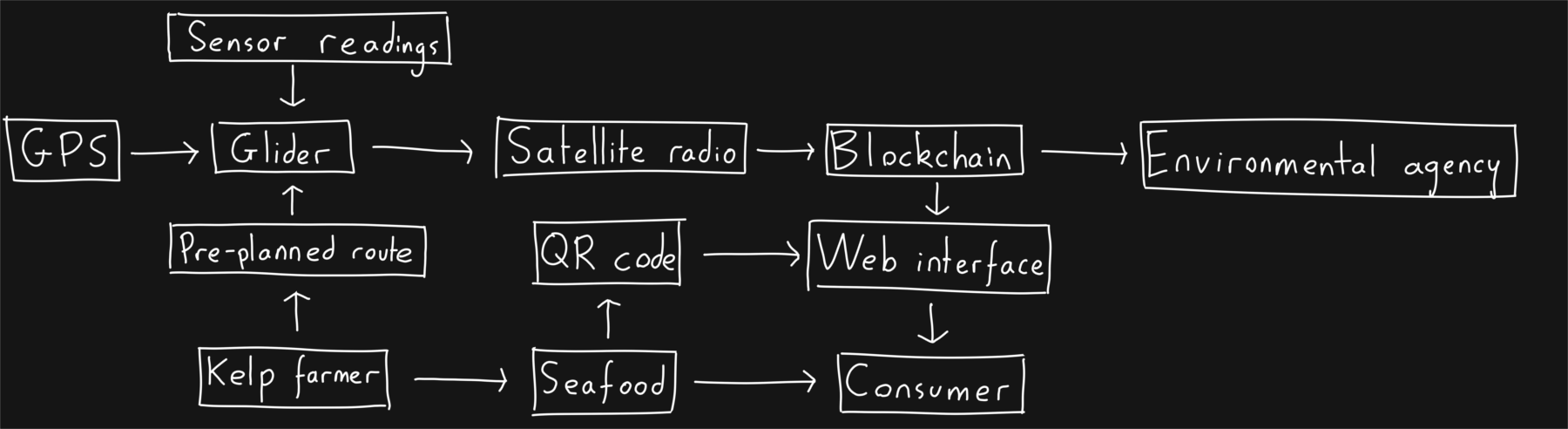 Above: A block diagram outlining the how the glider could be used for product traceability
How?
For the glider to move, the buoyancy engine takes in water and increases the density of the glider. When the density of the glider becomes greater than that of the surrounding water, the glider descends. The wings of the glider ensure that the glider goes forwards and the angle of attack can be altered to cause different glider characteristics. When at the bottom of the descent, the buoyancy engine will expel the contained water, making the glider more buoyant, causing it to ascend, moving forward again.
The buoyancy engine that I have designed uses an acme rod to move the ends of the syringes when rotated by a stepper motor, causing the plungers to take in water. When water is taken in, the volume of the glider remains constant, but the overall mass increases, therefore the overall density of the glider increases and the glider becomes less buoyant. At the centre of the glider will be a mass that controls pitch and roll. The mass shall be composed of Lithium ion batteries and steel rods, to form a substantial mass, so that it has sufficient control over the glider. The mass shall control the pitch and roll of the glider. The pitch will be dictated by a stepper motor connected by another acme rod to move the centre of mass forwards and backwards, thus moving the centre of mass forwards and backwards, affecting pitch. A secondary stepper motor shall drive a planetary gearbox to control the roll of the mass. As the mass shall be bottom heavy, when it is rolled to the left, the centre of mass shall move left slightly, causing the glider to roll slightly left and curve while descending. Rolling the mass to the right causes the opposite effect. A planetary gearbox was chosen as it increases the torque and accuracy of the stepper motor, allowing for finer control of the glider's roll.
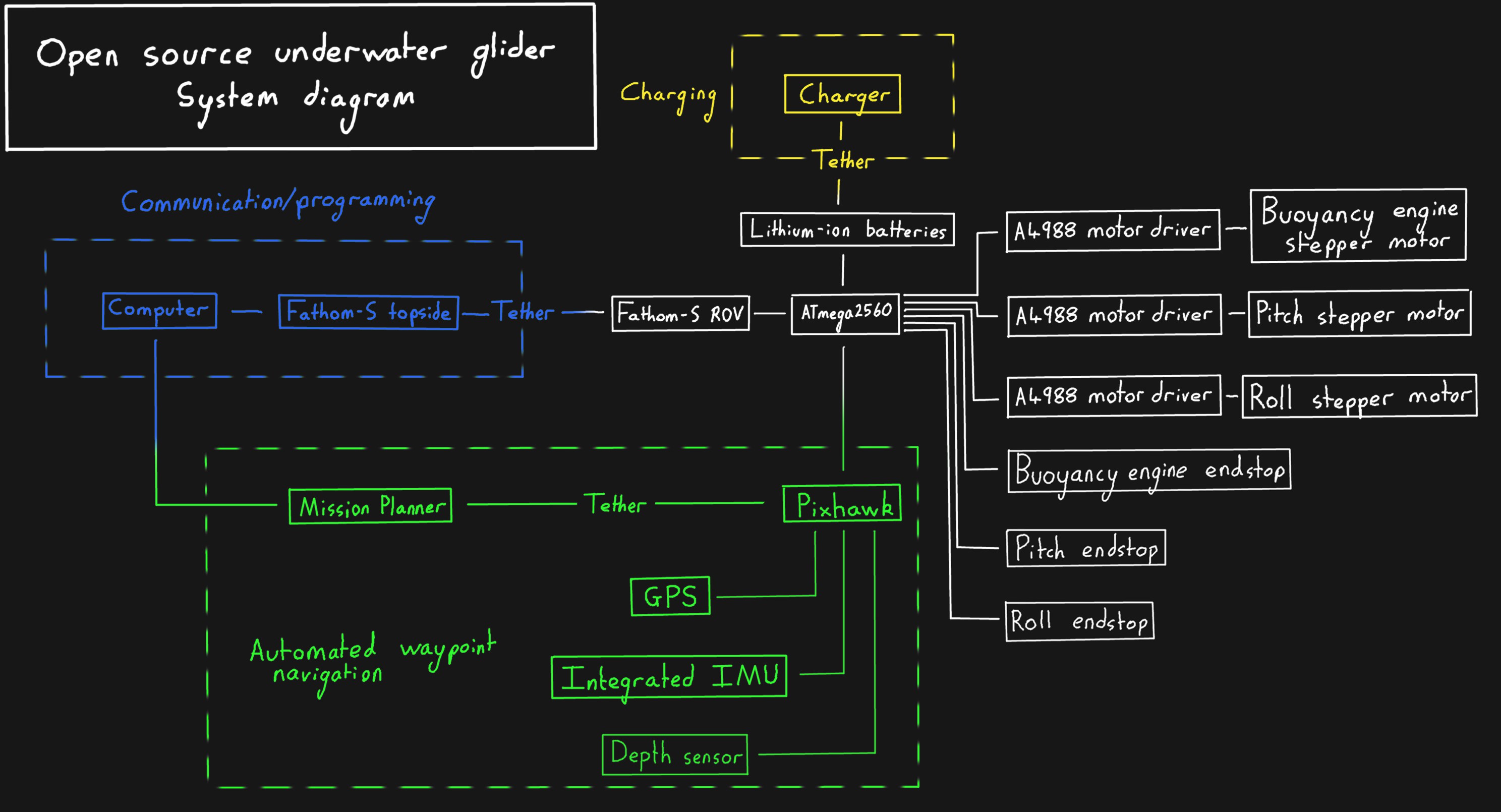
The depth of each descent is currently based upon a timer, but the current hardware includes a pressure sensor, which could allow the glider to switch gliding states when a certain depth is reached. Moreover, an IMU could provide information concerning pitch to the microprocessor (an ATMEGA2560) and this could use a PID algorithm to ensure that the glider maintains a constant angle of attack whilst minimising power usage.
The board uses Fathom-S serial communication boards from Blue Robotics, allowing for a neutrally buoyant tether to be attached so the glider can operate underwater whilst tethered (consequently, it can also be programmed whilst underwater, speeding up testing/development). This tether can also be removed and replaced with a watertight cap.
A system diagram showing how all of the different parts of the glider function together is shown below (click on the image to view the full size image):
Licensing
This project uses the GPL v3 license for all software related to the glider. A PDF of this license can be found at the top of the "Files" section.
This project uses the Attribution-NonCommercial-ShareAlike 4.0 International for all hardware components.