David Spinden
Overview
Problem: A ringing doorbell at the wrong time can wreck meals, naps, or a once in a life time moment (queue dramatic music). Furthermore, when you're away, how can you know whether you've had any visitors, packages, or neighbors stop by.
Solution: You need a way to route the switch off the doorbell, but still know if someone is delivering the pizza. Don't just cut the doorbell cord, leaving your friends hanging out in the cold, make it smart enough to send you a text or email you when they arrive. All while the baby is still sleeping upstairs.
Brilliant yet ingenious, I think so.
Final video:
First video (look how far we have come):
The Plan
Here is the plan getting the open source iDONT project off the ground:
Take the current doorbell system and break the connection after the 16-24VAC transformer. Relays controlled by an ESP8266 connect:
- The doorbell and bell/ringer to the ESP8266 for logging and sending information to a phone OR
- The doorbell and bell/ringer to the transformer for normal operation
The advantage of having the smarts at the transformer is that the system is powered off of the transformer...no full time battery operation and thus recharge.
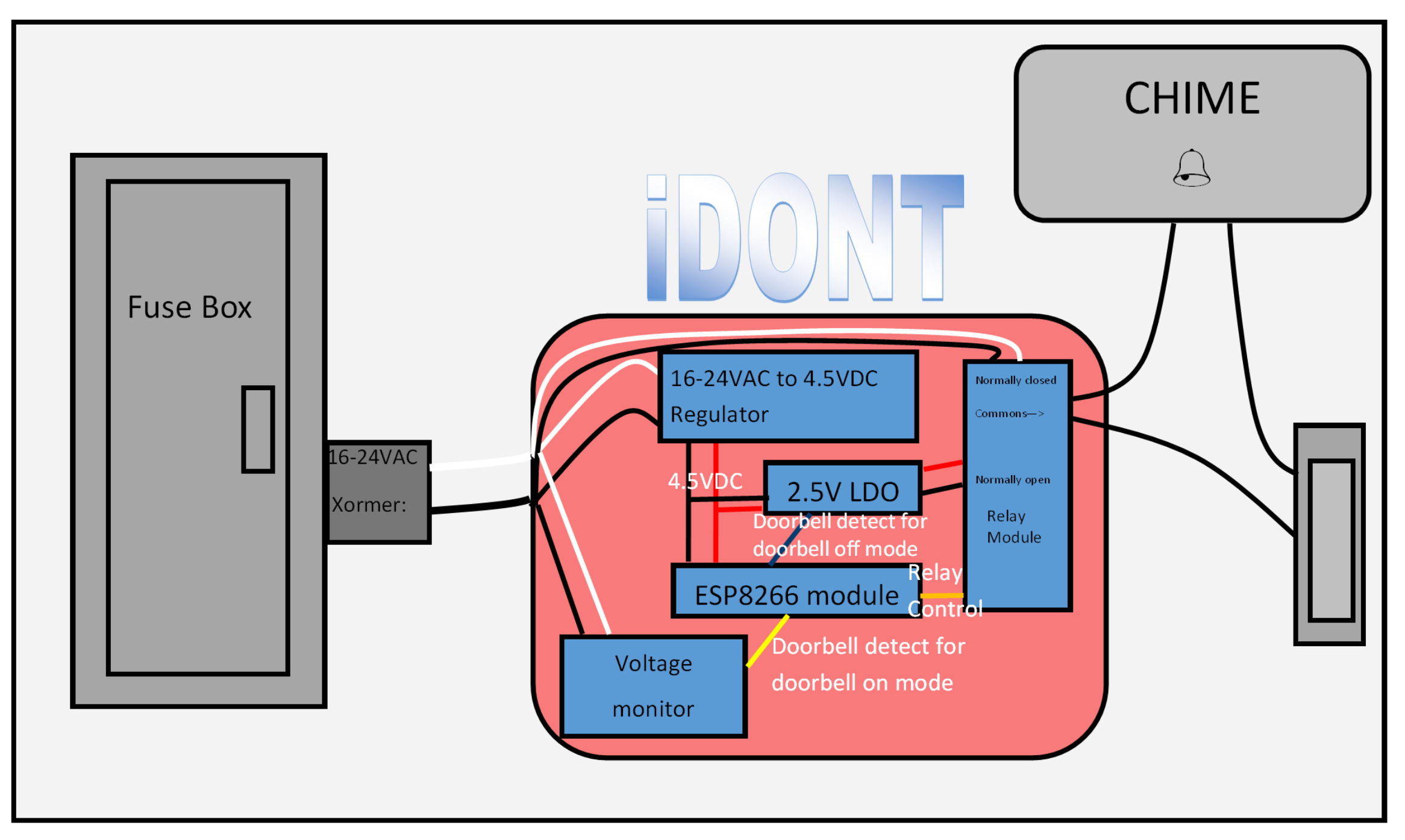
By using a double pole relay, I can either connect the doorbell to the AC transformer (normal operation) or to a 2.5V voltage regulator (LDO). In normal operation, the voltage drops on the doorbell transformer, so a voltage monitor detects the drop and an input pin of the ESP modules goes from 3.3V to 0V. In "off" mode, the 2.5V LDO is connected to the chimes and doorbell. When the doorbell is pressed, the LDO current limits and it's power good signal that is connected to the ESP module drops from 3.3V to 0V. All of this takes only five ICs plus a ESP8266 module and a relay module.
The cost of the prototype is be under $25 (IC costs is under $20 is quanties of 1 plus additional Rs and Cs and mechanicals) on top of the existing doorbell, chime and transformer. If this were to go to production, I would guess that the hardware would be under $10, given how few components are needed for a iDONT, but more for all the features I might have. Hackaday.io user Cdon raised the concern about the ESP's WIFI signal strength. So, I may need an external antenna for some people's setups...more costs.
The following flow diagram describes the basic architecture of the software:

A captive portal is an easy way to setup the iDONT. It allows any smart device or computer to control it without having to write an app for Apple, Android, and computer devices. The ESP8266 gets configured for the WiFi settings and setting message service to send a text alerting a person of the doorbell ring. The ES8266 also serves up a webpage to enable and disable the iDONT and config it.
That said, security still is concern. Given that a person has to be on the same network to interact with the iDONT, and the device is only connected to the doorbell it is a low risk item. Additionally, the iDONT has no way of making the chimes trigger, so there is no way to prank residents with this.
The Business Plan: See this log.
License: MIT Open Source
Milestones
The following shows my plan to build the iDONT. This will be fun mixture of hardware and software.
Software Milestones
- Install software to add the ESP32 to the Arduino IDE (done 4/1/17)
- Get the classic Blink example working (done 4/1/17)
- Control some relays (done 6/7/17)
- Build a hello world webpage and wifi setup (done 6/7/17)
- Build a webpage that controls the relays (done 6/7/17)
- Add email and/or texting to when the doorbell is pressed and in off/silent mode. (done, SMS and IFTTT working)
- Add logging abilities (bonus, did not add to ESP as with SMS/IFTTT your phone can store the messages creating a log)
Hardware milestones
- Get Blink LED example working (done 4/1/17)
- Get any old relay switching (done 6/7/17)
- Find and buy the right relay (done)
- Find and buy a doorbell kit to prototype with (done 6/7/17)
- Find and buy a AC to 5VDC power supply (not sure if will regulate before or after the doorbell transformer (done 6/11/17)
- Build the prototype doorbell, relay, ESP32, and power supply (done 6/11/17)
- Verify that the ESP32 can sense when a doorbell is pressed and the transformer is not engaged (silence mode) (done 6/11/17)
- Figure out how to sense a doorbell press when the transformer is engaged (normal operation) (done)
- Install in our real house (done, 10/19/17, see Sensors to Detect Doorbell Presses section below)
The "Competition"
After deciding to take on my wife's challenge of killing the doorbell remotely, I did some digging into what is already out there. There are a few solutions out there that are in this trade space.
- The Ring Video Doorbell certainly is a fancy device. It does a lot more than iDONT, but at a much higher price. Not open source. There are concerns over security: cnet's Ring Concern, iot-for-all Concern.
- The Doorbell Silencer offers a very similar solution to iDONT, but is still lacking. First, it is battery powered. This is a major negative. Who wants to have maintenance on their doorbell? Second, not being open source, reduces the options for future devices to control it and add on more features later. Third, at $60, it is still a price higher than most people want to pay for what amounts to a switch with logging. Forth, the Bluetooth pairing key is published on their front page, not the best security.
- A long list of other devices are coming out including a Nest Hello that sounds like the Ring.
None of these solutions are what I want. They do give me some better ideas of what is important. Given how few modules/components are needed for iDONT, a massed produced version would cost in the $10 range, about 1/20th the retail cost of the Ring. With all the Internet of Things (IoT) security concerns, adding a camera to a doorbell is opening up a can of worms
The Software
The software is in our GitHub repository. Here is Joel talking about the software at a high level:
Software Architecture
The firmware design is pretty simple; it consists of a number of state machines. A couple of state machines control both of the status LEDs, allowing them to be held on, off, or in a blinking state. A state machine watches the doorbell, debounces it, and generates an event when it's first pressed. And a state machine coordinates the system state -- what the iDONT should do when it's first powered on, how it should configure the wifi, and when it should begin normal operation.
Startup Sequence
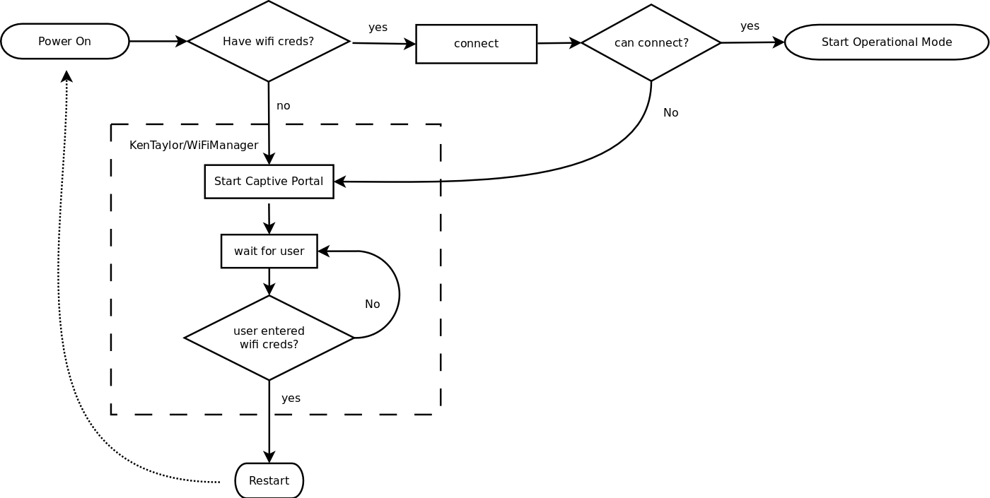
Before the iDONT hardware can begin normal operation, its key
features require a working wifi connection, and the startup sequence
is designed to make help it make that connection. If the user's SSID
and passphrase -- their "wifi credentials" -- aren't found,
or don't work, the main state machine will enter AP mode and start a
captive portal; when the user associates with the "Welcome to
iDONT" SSID, they will be presented with a page allowing them to
configure iDONT for regular operation. Once the credentials are entered, iDONT is ready to go!
Thanks to KenTaylor's WiFiManager library for furnishing this feature, we were able to focus on the main application logic. The startup sequence can be seen here:
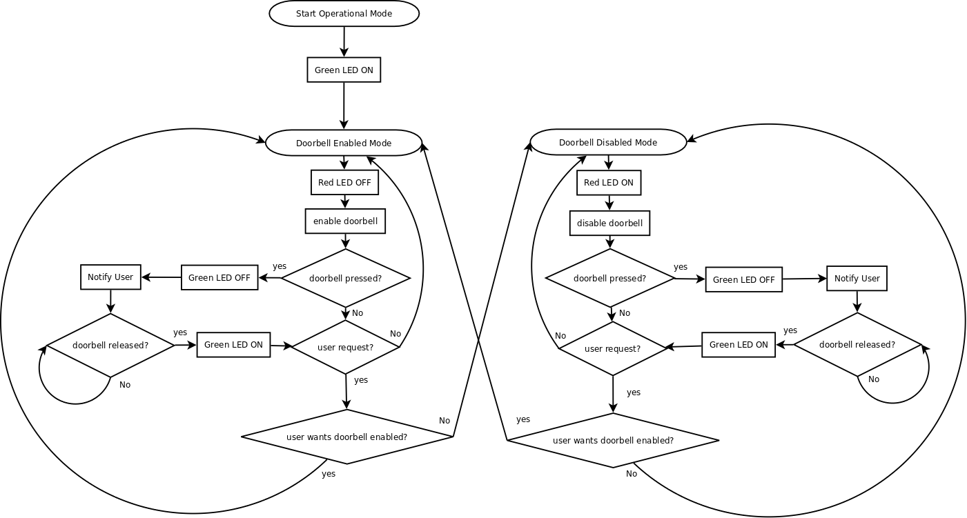
Operational Mode
Once in operational mode, the task is simple: notify the user if the doorbell rings, and update the status LEDs to reflect events as they occur (this is useful for debugging the iDONT during development and installation.) In this case, we want a green LED lit in operational mode, and the red LED lit if the doorbell is currently disabled. During the moment that the doorbell is pressed, we temporarily turn off the red LED to show that the software has acknowledged the software. Here is a detailed diagram of these state transitions:
All in all, the software design is pretty straightforward, so most of the effort was simply debugging and integrating the software design with the hardware. The popularity of the Arduino IDE, ESP8266 chip, and the NodeMCU board helped the firmware development process, as there were many forum posts, utilities, code snippets, and libraries to adapt and learn from. The result is a easy-to-grasp design that other hackers are free to modify and improve.
The Hardware
Hardware overview:
After first breadboarding the parts, I switched to soldering a second prototype on an anyboard. The relays and ESP were on their own board.
Like I said in the plan section, there are only five ICs in the this setup apart from the ESP module and relay module board. Pretty easy to prototype or run to production. Other than the ESP module with built-in antenna and USB UART, and the relay module board with opto-isolation, there are just a few parts broken into two categories:
Sensors to Detect Doorbell Presses
In the first prototype, I bought a constant current module designed for things like LED lights. I set the current limit low and when the doorbell was set to off mode (no chimes), the constant current regulator and ground was connected to the chime and doorbell. When the doorbell was pressed, the current limit was hit and a doorbell press could be detected. Problem was, the module used many components and was way overpowered: 2A, when I only need 25mA or so.
In digging further, the doorbell chimes start making sound when 5V or more are applied. In iDONT "Off" mode, we want to detect a doorbell press, but not make a chime. The TPS7225 voltage regulator was selected because of its low current max, power good output that can be easily monitored, DIP package option, and very few external parts. Other LDOs can be used, but it needs to have a power good and voltage needs to be less than 5V.
In short, here is how it works: When the doorbell is pressed, the 2.5VDC voltage is shorted and power good on the TPS725 drops to 0VDC.
When the doorbell is "On" (chimes operating), I noticed that the rectified voltage drops from around 29VDC to 18.37VDC. Instead of sensing a doorbell with a current sensor that requires an ADC and possible calibration, I decided to go the voltage sense route. As I only need one bit precision, a voltage monitor with an open-drain type output makes sense (get it?). Not finding any high voltage (that is above 6V) monitors in Digikey that were simple three terminal devices, I decided to use a resistor divider.
Voltage Regulation
In order to be powered off of the transformer (no batteries or additional AC to DC "wall warts."), we need to make our own AC to DC converter. Because the doorbell transformer already steps down the voltage to 16VAC, it is easier to use a simple bridge rectifier and DC-DC regulator, either a linear or switching regulator. I had a LM317T LDO linear regulator in my parts bin, so used it. Not ideal from a efficiency standpoint, but able to handle the rectified 30VDC.
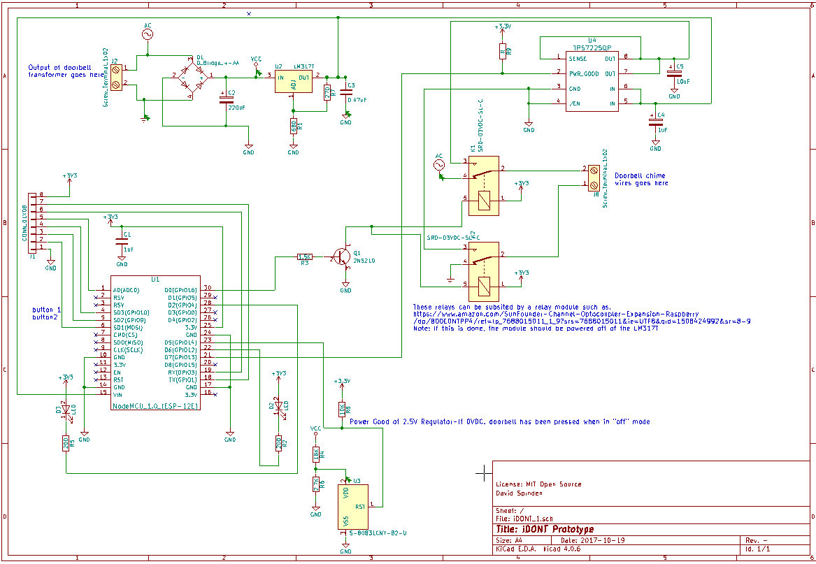
The Schematic
The schematic was done in KiCad and is included as an attachment. Here is a picture of the schematic: