 Tron9000
What I wanted out of this supply:
- Be small and compact
- output adjustable to 20V
- Use mostly salvaged and recycled components
- display the voltage and current
- Fine adjustment of output voltage
- Adjustable current limiting up to 1A
- Mains supplied
- Linear topology based on a single quad packaged op-amp and all THP construction circuitry
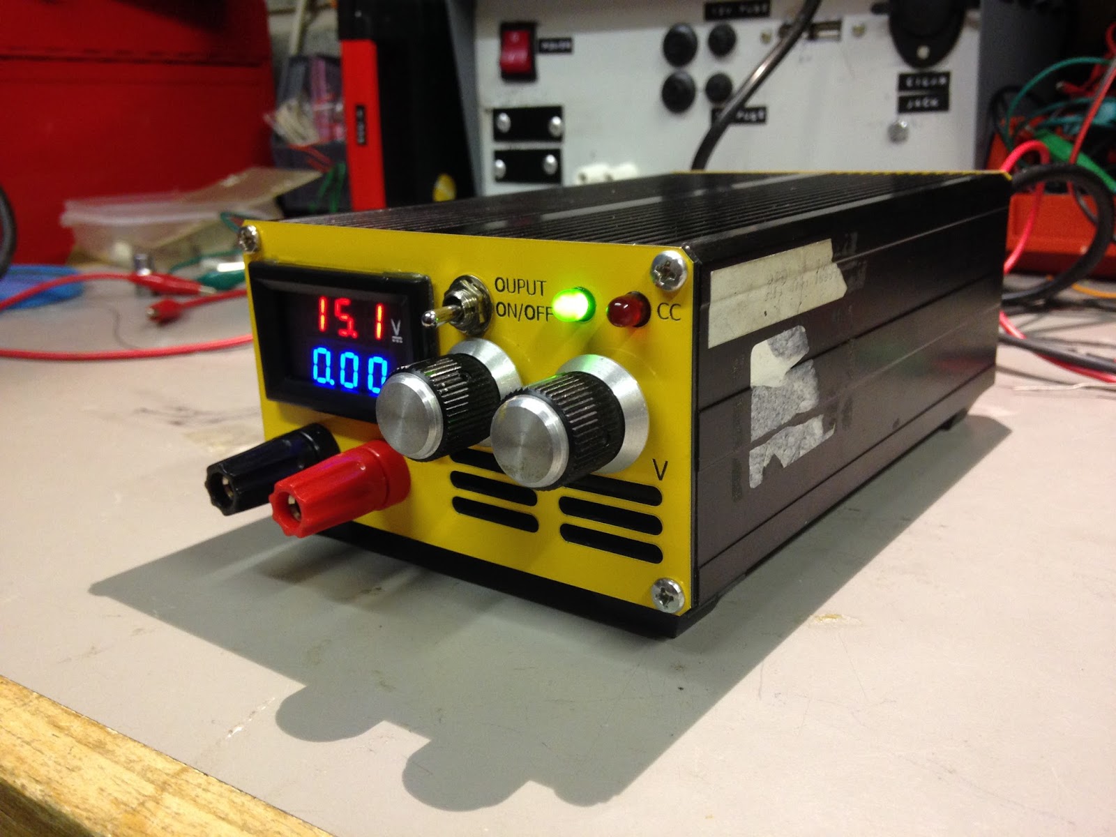
This is my first Power supply based project the other day and thought I'd start with a modest one. Here's how it came out:
Now there are loads of designs out there, so picking is as easy as punching the right terms into google. The most popular of which seemed to be Dave Jones +EEVblog based design, which is based round an LT3080.
|
A popular design but I wanted to tweak it a little |
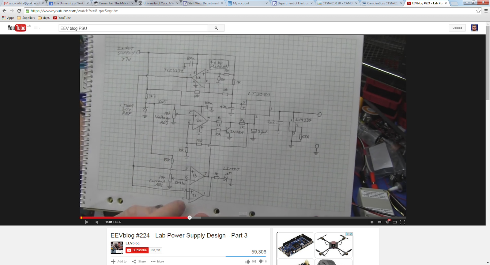
Not having one of those in my box I decided to base it on an op-amp and pass transistor instead. So you could say a less polished version of the EEVBlog design.
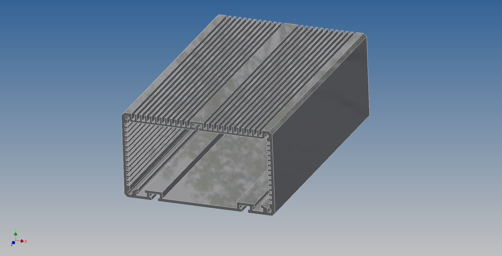
Hunt for partsAfter a rummage round my parts bin I found a 18V 20VA transformer which would be perfect to power my design. I needed an enclosure and the enclosure I was going to use for my Load project seemed to tick all the boxes: light, small, robust and the transformer fit inside! So that put 2 high value components off the shopping list!
|
Pass transistor: found a TIP3055. Seemed to be up to the task. The next high-ish value item was the heatsink. The transistor may have to dissipate up to 25W (18x1.41 = 25.38V x 1A = 25W and a bit, I'm assuming full load at near 0V output).
Then looking at the enclosure, the answer was staring me in the bleedin' face! I know working out the case thermal resistance was going to be a brain ache, so I didn't bother! Its a big chunk of metal with a large-ish surface area on the top! I just went with my gut - admittedly that's really not what your supposed to do, but if it didn't work then I was confident I could figure something out!
Other parts: well there are always resistors and caps, but I need a quad packed op-amp: LM324 - yep got one of those! Also a good power supply is based on a decent voltage reference. I didn't want to use a Zener as a reference as their temp coe. and initial accuracy can be poor and after some careful sorting of my parts I found a couple of AD680's. Very nice! Good temp coe. and initial accuracy!
The temperature in my garage can range from bloody freezing to quite comfortable in the space of a day and I'd rather not have my output be dictated by the weather!
Testing the theoryAs with all designs, you first get some testing done. Using SIMETRIX I started testing some designs and observing their performance.
|
I went through loads of versions - this is version 5 |

My main hurdle was figuring out why my output voltage was so noisy. Then it became apparent I'd not thought about how my voltage feedback was working. Originally the feedback to my voltage error amp (X2) came directly from the output of the supply. When running the simulation and observing the output I first thought that I needed some filtering in my voltage feedback (C3) as from the response I got:
|
When you think your on the right track, you sometimes find yourself still going in the wrong direction! |

But after looking at the design I was basing mine on, it was clear what I had done wrong! So corrected the feedback and removed C3. I then found that the output became much more stable!
Further simulation also showed that my output needed some regulation current at low voltages and some damping in the voltage amp feedback. Below is a revision of schematic version 5 (above) with the constant current source I1 set to step through different values of regulation current (0-10mA) and C3 is now a 47uF cap connected to the non-inverting input of X4:
|
V5 rev1, C3 is now 47uF and position moved and I1 will step through on simulation |

Firstly I wanted to see how the output voltage responded to different regulation currents. So I firstly I ran a transient simulation without C3 and set the source V4 (my reference) so that I would get approximately 1V output, and obtained the following:
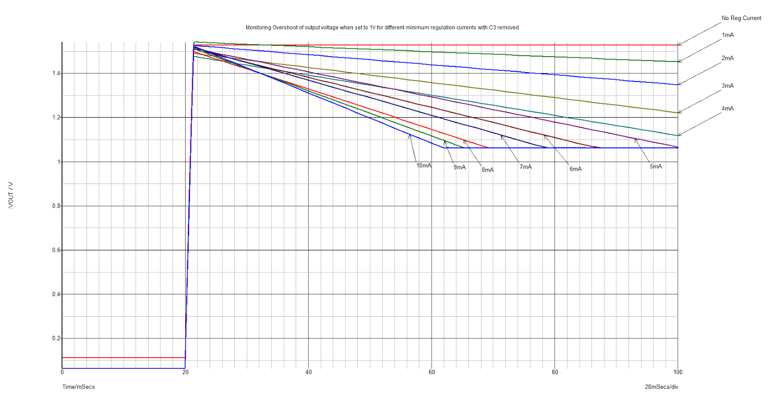
As it can be seen, that having even a small regulation current on your output means your output voltage will regulated properly, it can be seen at no regulation current that it never reaches its set output voltage!
Obviously the rate at which it falls towards its set point is proportional to the amount of capacitance on the output and the regulation current (falls faster at higher reg currents). My design has quite a bit as you can see (880uF = 4x 220uF) as I would like as little ripple as possible on my output under max current output.
As it can also be seen there is a lot of overshoot! The transient response shoots up to 1.5V and then slowly falls. This is NOT IDEAL. At higher voltages above 1.5V, this overshoot was not as obvious, but voltages below 1.5V it was very apparent! Not good for testing low voltage, sensitive devices.
This is where C3 47uF cap comes in. I added this cap to the feedback loop for X2 and there was a vast improvement in overshoot:

So as it can be seen, with no reg current it still doesn't regulate the output properly, but is not as high. As reg current increases, the recovery from overshoot is quicker, however, too much reg current and there is a tiny bit of undershoot too, so you get some oscillation, but its hardly noticeable.
The overshoot is much less: <100mV.
Feeling devil-may-care I increased C3 to 470uF to to see what happens on the output:

All the different traces for the output for different reg currents are on top of each other, except the case where there is no reg current. You can see the again the overshoot is less (nearly 0 in fact) and that the 0 reg current output is also less. But look how slow the output takes to respond to the transient! That too is not ideal.
One thing that is also apparent with no regulation current is that the output when the set point is 0, is floating about 100mV above 0V, which can be seen in all simulations; another non-ideal case.
I tested the current limiting circuit and the response was as below:
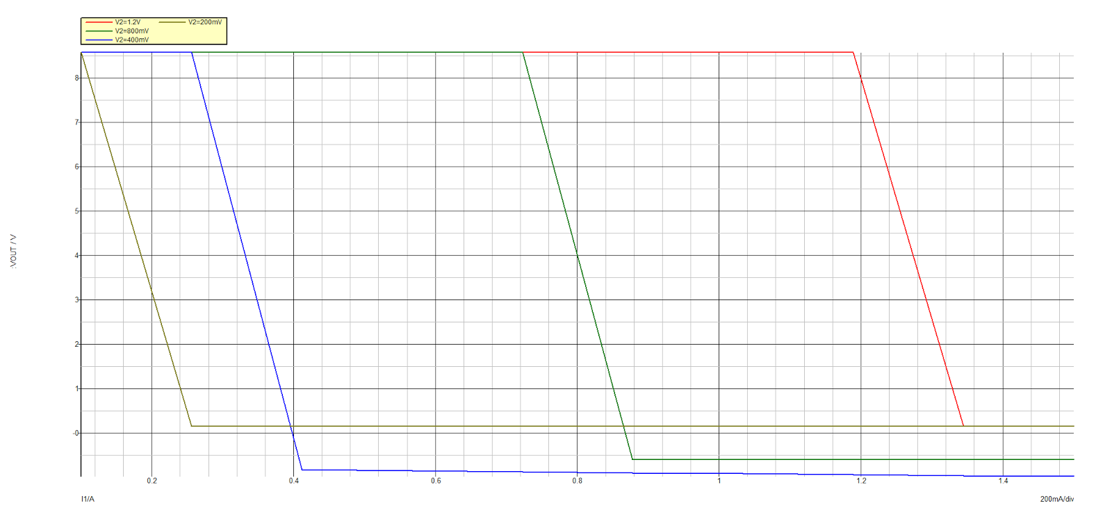
V2 is the set-point of the current limit amp X1, again I ramped I1 (now acting as load current), for each step of V2.
Its a bit strange as 2 of the traces go below 0V, but still they are roughly what I was expecting, but a bit off. I'm not too concerned about how well it current limits.
I don't tend it use constant current mode an awful lot, I'll be mainly use it to ensure that the device I'm powering doesn't overload. So so long as the output voltage goes down once current limit is reached these results are acceptable.
ConclusionsSo I settled on 47uF for C3 and a reg current of 10mA. So armed with this schematic and data I moved into CAD.
Goes to show that testing does help refine your design, help understand what's going on and also learn a little bit about the process. I learnt that small amount of regulation current is important and why. Doing it in a SPICE environment also takes the pain out of getting things wrong and having to replace parts on a bread board for example.
I must admit that most of my simulations were based on suck-it-and-see testing, but that's sometimes a good way and if you have some idea of how it works then understanding what's going on becomes apparent.
Proceeding onI generated a schematic on EAGLE based closley on the simulation schematic. Schematic is shared here: Mini PSU schematic V3.6
Features:- adjustable current limiting output
- multi-turn adjustment pots:
- 10 turn voltage adjustment
- 3 turn current adjustment
- Switchable output
- 19mm spaced 4mm binding post terminals
- voltage and current display
- Stable reference source:AD680 2.5V reference
- Single, quad package op-amp design(LM324)
- CC mode indication LED
- Compact design!
- Tough extruded aluminium housing
- custom, laser laminate panels
I complied a log of all the work I did here: PSU Build Log
Inside during development |

Briefly: it outlines the usual things: starting off with the case and panels, trying to figure out how everything goes together, testing, hiccups along the way: like the panel meter being wired incorrectly and dying, the Transformer I acquired giving up the blue smoke and the panels breaking due to my ham-fistedness!
On the fly modifications |

Bit of testing |

I was pleased with the results from testing. Although I was testing with not exactly accurate and precise instruments, it didn't matter, it does what its supposed to do, and so what if its a bit out? And do I also need bucket of amps? Not really! Why start out big and out of your comfort zone when you can start small, work up and enjoy the exprience? Its a PSU, built out of scrap and eBay bits. It looks the part, its nice and compact and I managed to achieve my spec and I learnt A LOT about building a linear PSU (like the importance of a small amount of regulation current)
Pride of Place! |

Improvements
I added some extras on at a later date
- Better resolution display - 0-33.00V 0-1A-3A Four Bit Variable Precision Voltage Current Meter DC Double Digital LED Display Voltmeter Ammeter
- Better op-amp: I have an LT1014 kicking about so will fit that next
Some of these will be implemented next when I get round to it but for now: she does the job!
|
Powering a dismantled cheap-o tablet |

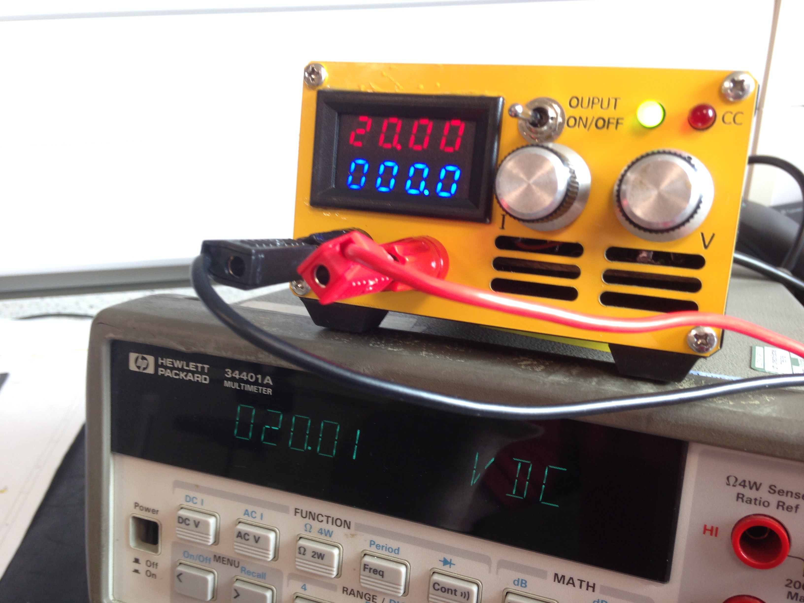
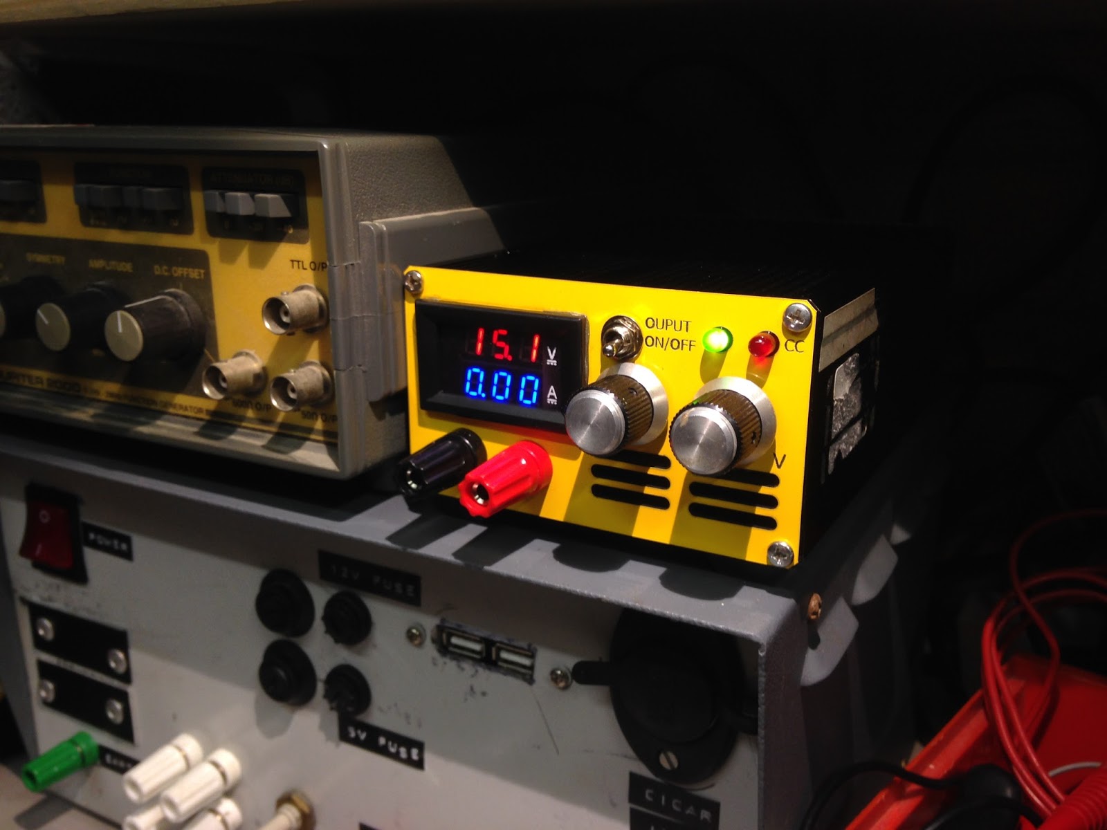
After I installed a new better resolution display and better op-amp, I gave it a quick validation on a more accurate DMM at work and its pretty close.
Even though this is a finished project I may still end up doing more work on it like characterising its output properly, but for now it does the job.