To start off with, this is just the compressor, not a jet engine. A jet engine is comprised of a compressor, a combustion chamber, and a turbine. I built this to be run with an electric motor. I wasn't planning on building a combustion or turbine stage.
Being a recent grad, I didn't have a lot of money, really all I had to my name was my computer and my 3D printer. So to design an axial compressor to a good degree of efficiency I had to do a few things on my own.
An axial compressor is comprised of rotating rotor blades and static guide vanes, or stators. The whole trick to increasing pressure is not allowing the velocity of the air to increase that much. If the engine were made of only rotors, the velocity would increase with each stage. But with the static stators in place, they reduce the velocity of the incoming air and increase the pressure. However, with pressure/velocity increase, temperature must also increase. To put into perspective how much, the inlet temp vs the outlet temp of my model is projected to be just under 400 K in difference.
Designing a compressor relies, really, on only five things:
- The atmospheric conditions
- The size constraint of the engine
- The reaction coefficient, R
- The stage loading, Psi
- Flow coefficient, Phi
R, Phi, and Psi are defined by these three equation
R is essentially, the amount of work the rotor and the stator are doing. So for 0.6 reaction, 60% of the work is being done by the rotor, and 40% by the stator. Ideally, the value of R should be kept in the 0.5 - 0.65 range. It is half the stage loading multiplied by the sum of the tangents of the inlet relative angle (b1) and the relative outlet angle (b2) of the air from the rotor blade.
Psi is similarly designed by the flow coefficient and the the inlet outlet angles.
Phi, is a non-dimensional term expressed as axial velocity over the blade speed.
The angles of the rotor blade can easily be calculated using a velocity diagram, not unlike the one below.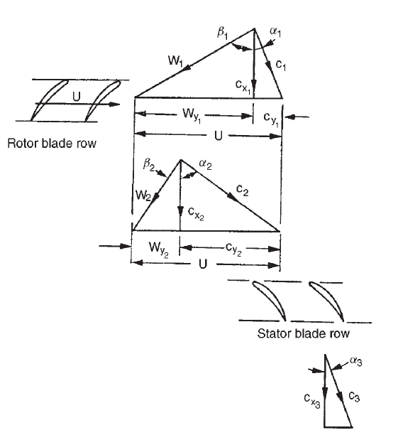 (I'll come back and add more details later but let me explain the project)
Calculating R, Psi, and Phi, along with all of the other necessary information to generate a rotor is a very recursive task and not to mention you have to repeat the process for each stage. Luckily, there is a free program out there that does this quite nicely, LUAX-C. Developed by the nice people at LUND U. I'm working on incorporating a Python version of this process in my compressor program, described below.
This allowed me to have the necessary information to designing my compressor, along with some approximations on to the performance. But designing the blades using the information was another hurtle. I'm decent at CAD but no-where near patient enough to design these blades with the angles they needed. So I wrote a Python program that generates the rotors and stators for me, I attached it in the link section. It uses PyQt and Numpy-Stl to allow the user to generate a rotor and stator to be exported as an STL.
PLEASE NOTE: The program, although tested, is brand new and probably buggy. I'm still working on the re-write to make it cleaner and what-not.
After designing the rotors and stators in CompPy they were then finalized in an external CAD program. Mostly what I did was just reduce the vert counts, bored the axle hole and made sure they were solid.
The stators were then built into the case itself. I toyed with this idea for awhile, my first three iterations had separate stators and I just felt it was too many parts; plus commercial jet engines use a similar 'clam-shell' stator/housing combo.
Next the bearing housings needed to be made. These would hold the ceramic bearings in place.
The final step was to create the spacers and the coupler. Ideally, the space between a rotor and a stator should be zero, but with that being impossible, I had to get compromise. I needed enough room to create the transitional space between stages but not enough where stalling could lower the efficiency. The spacers separate the rotors such that they are within 2 mm in front of their respective stator and around 5 mm behind the preceding stage.
*This is where I am in the process to those wondering*
From here, I'd 3D print everything and make sure everything fits, spins, and play along nicely. If, and it's a big if, that all works out, I'll strap a motor to it and see what happens. Being plastic, I anticipate it going to melt, but that's point. If it melts and produces thrust, I'm on the right track.
I'd then cast the rotors and stator-housing in aluminum. To those wondering, cast aluminum has a tolerance of around 300 m/s for the tip speed, so it should be fine. I'll machine the bearing housings because I need that extra precision (I can't have the bearing misaligned).
Then we'll fire that up.
So now some specs for my compressor. I won't include the reaction, flow, or loading coefficients; those who want to replicate something similar shouldn't be given the answers.
- Stages: 4
- Pressure Ratio: 1:24
- Designed RPM: 30,000
- Inlet massflow: 28 kg/s
- Temp rise: 397.3 K
- Specific massflow: 474.6 kg/(s m^2)
- Inlet Diameter: 80 mm
- Outlet Diameter: 24.5 mm
Something to note is the designed RPM. Most axial compressors run at around 6000-8000 RPM, I chose mine to run at 30,000 (hence why the stages look a little strange). I did this for multiple reasons. The compressors on a typical jet engine are comprised of >10 stages, this allows for the air to be heated enough to ignite the gas. Mine, being designed to be the size of a soda can couldn't be that many stages. The precision needed to build the rotors and stators would be beyond that of my, or other hobbyist, tech. Also, not needing to build the turbine section, I can determine the speed of the motor and hobby electric motors can easily reach speeds of 30,000 RPM with a nicely built gearbox.
(MORE TO COME AS TIME PERMITS)