This project can also be found at https://www.instructables.com/id/Multichannel-Wireless-Light-Dimmer/
Save Energy Beautifully !!
By using a light dimmer in one’s living room, it’s possible to completely alter the mood and ambience of a room at the drop of a hat.
The
Internet of Things is set to disrupt the way we live and work. Smart
homes filled with connected products are loaded with possibilities to
make our lives easier, more convenient, and more comfortable.
With Wi-Fi connectivity present in the dimming controller, the above benefits get reflected in this module. However, this actually carries with it a host of less obvious but equally favorable benefits such as reduced energy consumption and improved longevity - longer the bulbs are dimmed, lesser the energy they use and longer they last.
This project aims to
● Control the intensity of the dimmable lighting appliances via a trailing edge dimmer.
● Provide the user , ability to control lightsindependently and wirelessly over the Wi-Fi network and the Internet!
Project Demo:
Specifications
- 2 channel dimmer module for indoor lighting applications (# channels can be easily expanded as per need)
- Can be easily setup in Trailing Edge/Leading Edge configuration with some small variations in the software,hardware remains the same!!
- Rating: 200 W/channel
- No minimum load on any channel (True 3 wire dimmer!!)
- Wireless control via Wifi (Uses the popular NodeMCU module)
- Web Interface for controlling dimmer settings
- Can be controlled from any device with browser support (Chrome, Firefox)
- Supports OTA(Over the air programming) for software updates
Nice..,isn't it you too can make one for yourselves!!,I have spent a few months understanding and making this dimmer module.
You will find all the source files,step by step instructions and things I experienced while making this project compiled in this instructable.
I hope you would learn a lot and enjoy as you proceed further!!
Understanding Light Dimmers
There are two main categories of traditional AC dimmers (also known as 'phase-cut' dimmers)
- Leading Edge Dimmers
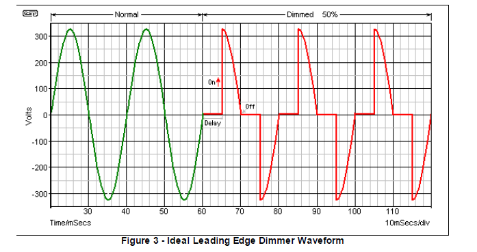
- Trailing Edge Dimmers
These vary the brightness of the lighting appliance by varying the rms voltage applied to the load.
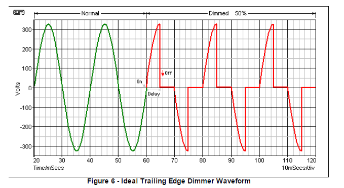
This design uses a Trailing Edge Dimmer
They provide a 'soft start', increasing the voltage to the lamp relatively slowly.
With
incandescent lamps, this almost eliminates 'thermal shock' - that brief
period at switch-on where the lamp draws around 10 times the normal
operating current.
By including the soft-start feature lamp life is increased, but it doesn't help CFLs or LED lamps much.
Trailing edge dimmers commonly use a MOSFET, as these require almost no control current and are rugged and reliable.
Another option is to use an IGBT (insulated gate bipolar transistor), which combines the advantages of both MOSFET and bipolar transistor. These are generally more expensive than MOSFETs.
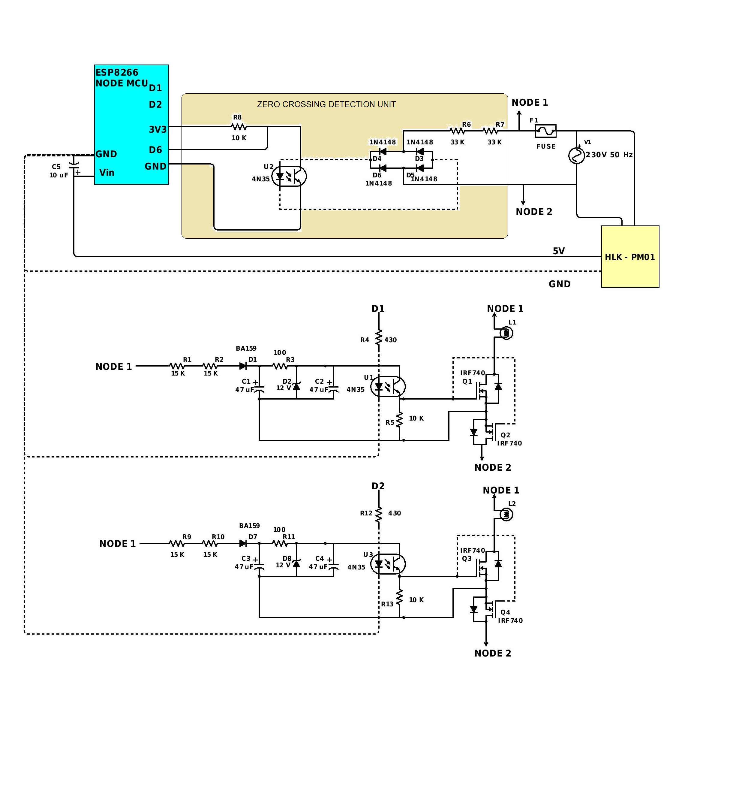
Schematic:
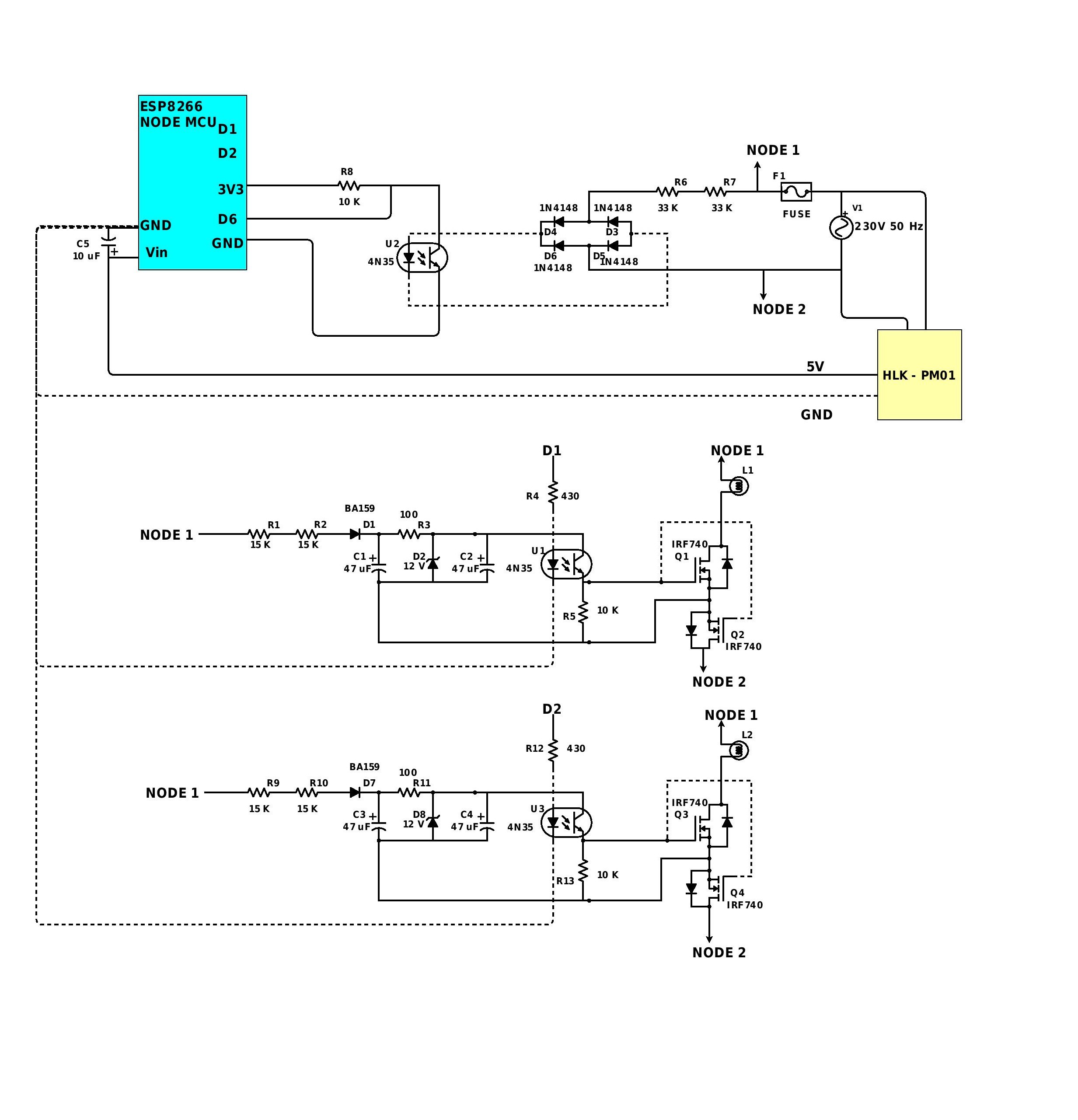
Each subsection of the schematic has been explained in detail further.
Zero Crossing Detection Unit:
- Diodes D3,D4,D5,D6 form a bridge rectifier.
- U2 is an optocoupler(4N35), and its LED is powered via R6 and R7, and then from the bridge rectifier.
- The interrupt signal is provided to NodeMCU via pin D6.
- R8 is a pull-up resistor.
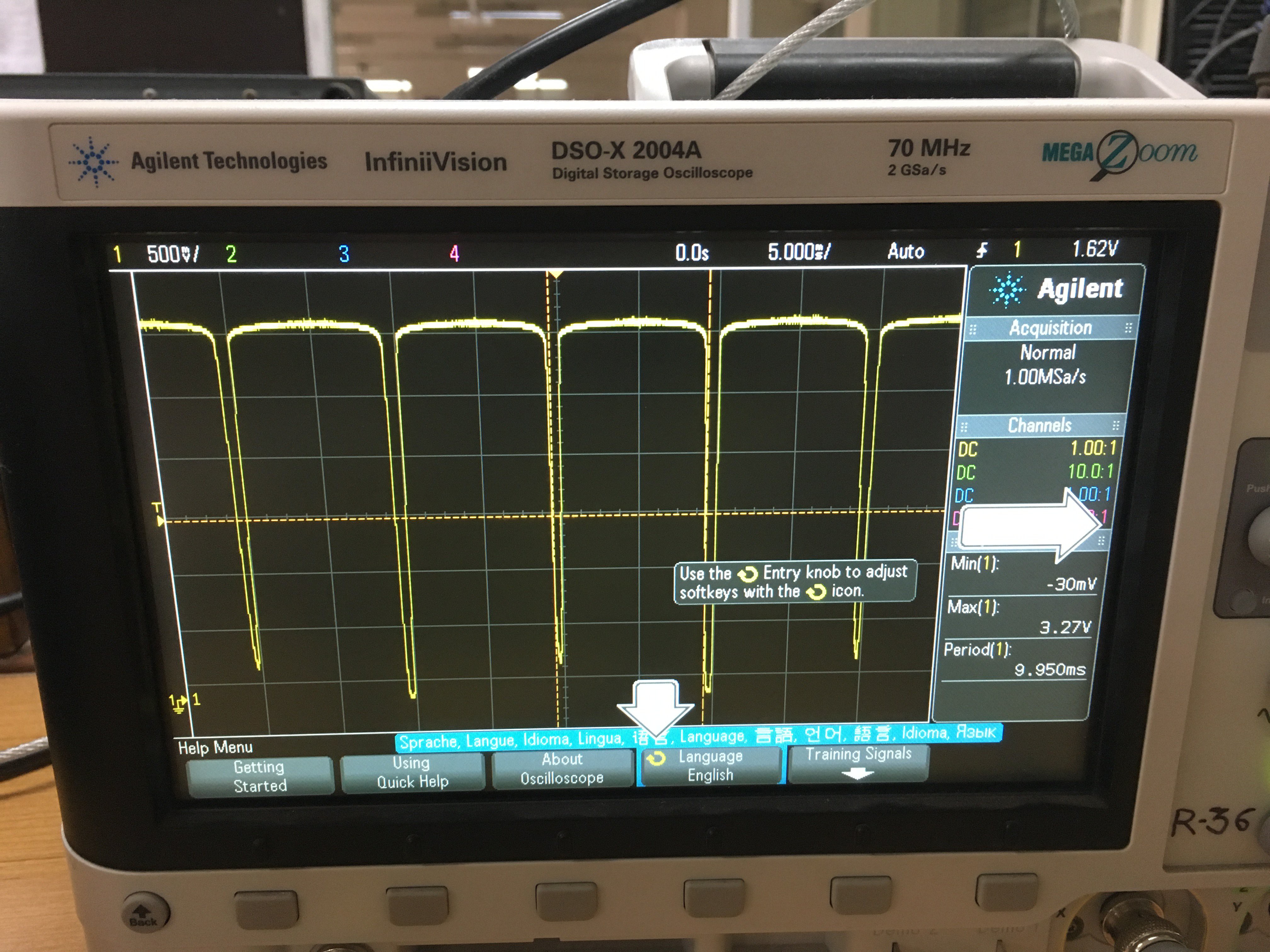
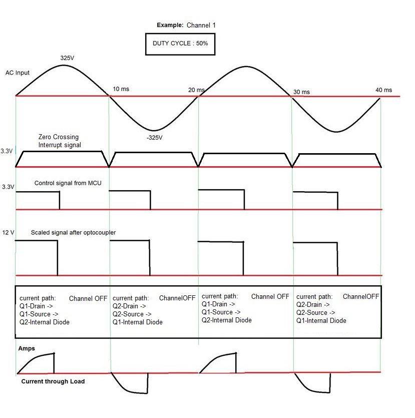
- The zero crossing detector, gives a negative-going pulse when the mains voltage is close to zero.
- This is used to synchronize the mcu to the mains, and is really the heart of the circuit.
- A series string of 33K resistors is used instead of 66K resistor to divide the total of 1W power dissipation.
12V DC Supply:
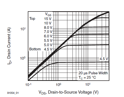
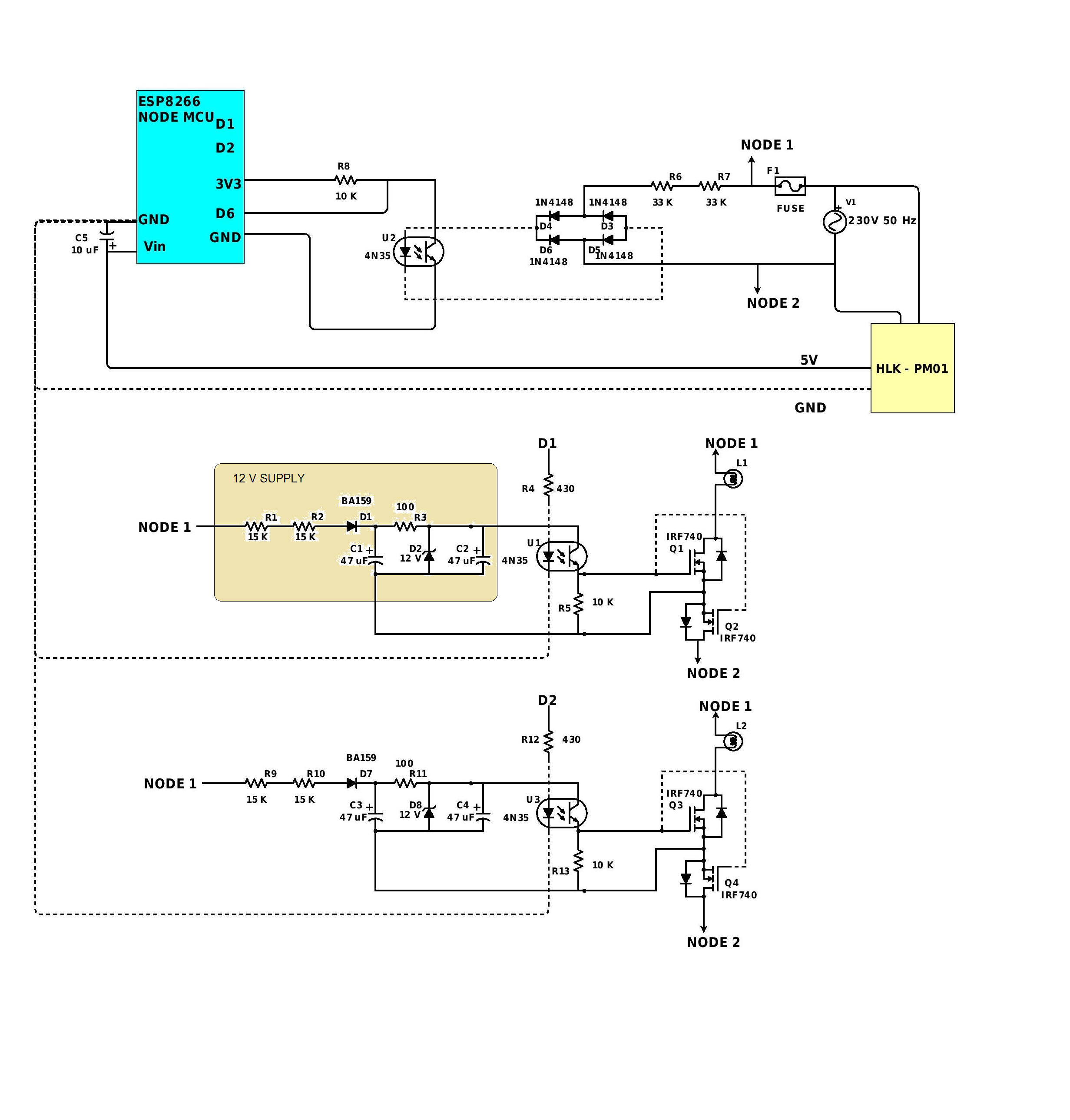
To minimize the switching losses in the mosfet IRF740, the gate control signal from the mcu is scaled to 12V.
Note: Each Channel needs it’s own dc supply.
- A Fast switching diode BA159 is used to rectify the AC input.
- D2 is a 12V zener diode
MOSFET Driver:
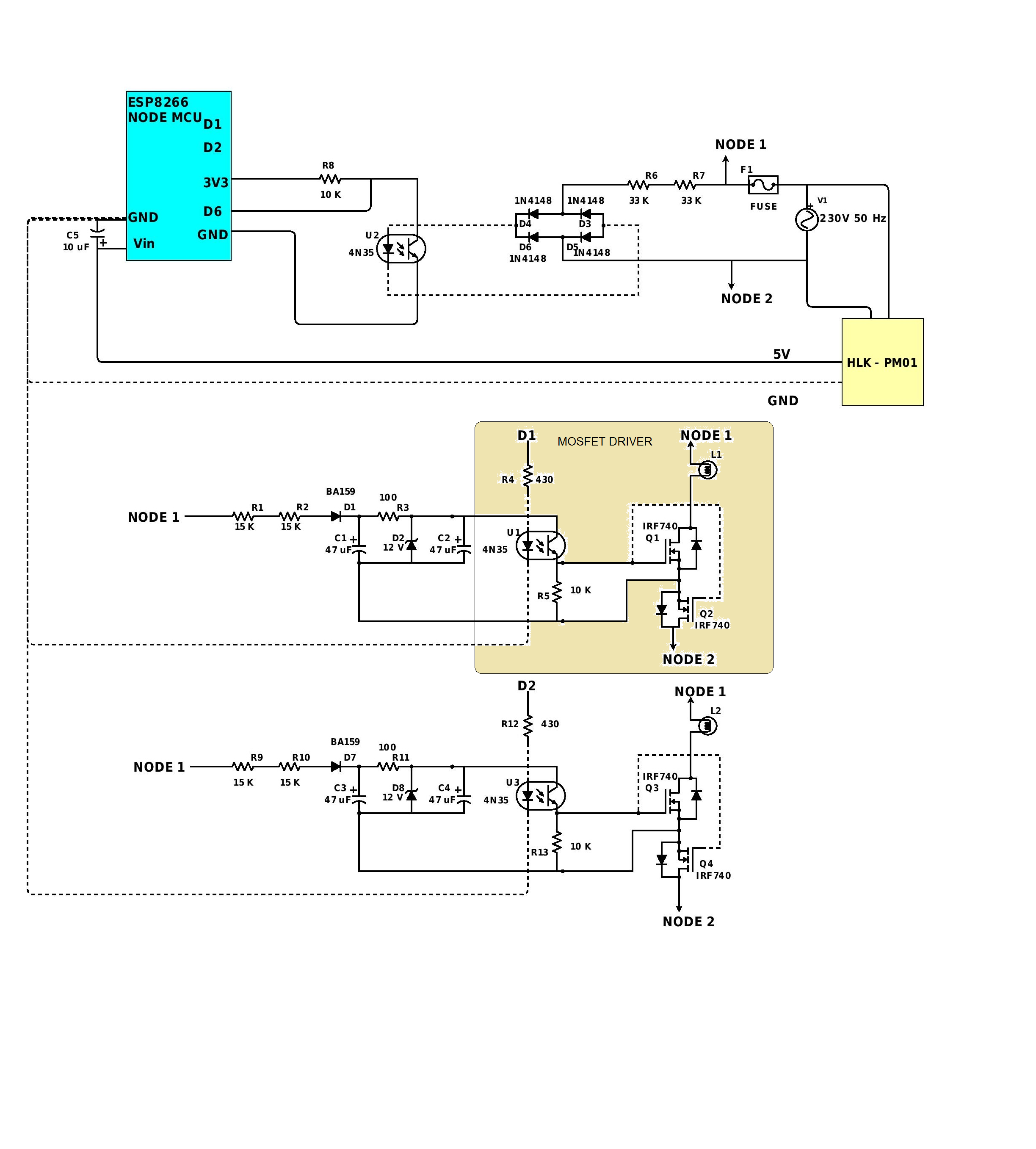
- The AC switch is formed by two N-Mosfets in a series configuration
- 4N35 IC provides the necessary isolation from the mains
- The control signals from the MCU are fed to the optocouplers U1,U3
DC supply to MCU is provided by 220V AC to 5V DC 3W PCB Mounted Plastics Enclosed Isolated Switching Step-Down Power Supply Module (HLK- PM01) having compact form factor.
Putting Everything Together:
After understanding each of the sub units,functioning of the entire circuit is illustrated here.
Designing the Web App:
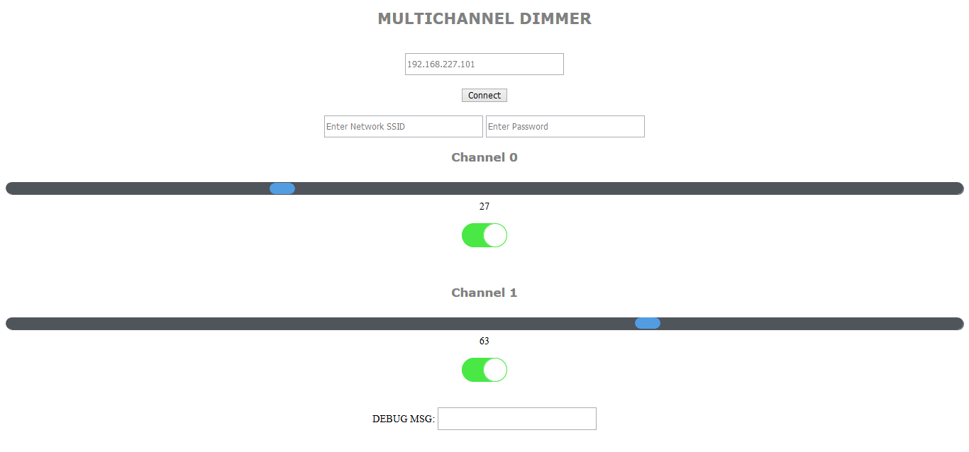
- The Web App source is a simple HTML file and uses WebSockets for handling clients.
- Currently one needs to enter the IP address of the access point to get started (which is saved in the device automatically for future use)
- The Network SSID and Password are hard coded into the system(You would need to modify the code to dynamically change the network)
- The Web App Controls channel states (brightness, ON/OFF) via sliders, toggle switches.
- Can be deployed on any device that has access to browsers like chrome/Firefox and Wi-Fi connectivity. (Note: the sliders are sluggish on android devices,may need some UI improvement)
- Displays Real Time Channel states.
- Eliminates the hassles of single remote as any number of users can directly control the settings via smartphones/laptops/tablets.
Programming the ESP8266:
Arduino IDE is used to program the NodeMCU ESP8266 module.
- Download the latest version of Arduino IDE fromhttps://www.arduino.cc/en/main/software
- Start Arduino and open Preferences window.
- Enter - "http://arduino.esp8266.com/staging/package_esp8266com_index.json"; into Additional Board Manager URLs field.
- Open Boards Manager from Tools > Board menu and install esp8266 platform
- Select NodeMCU 1.0 (ESP 12E module) board from Tools > Board menu after installation
- Install WebSockets library by markus sattler from Sketch > Include Library > Manage Libraries
https://github.com/esp8266/Arduino
- Trailing_Edge_Dimmer_v5.ino
- dimmer.h
- hw_timer.c
- hw_timer.h
PCB Design
- Follow these tutorials for setup and basic understanding of EAGLE CAD software:
- The PCB was designed in EAGLE CAD(7.2.0)
- The EAGLE Files have been provided in this step.
Note:
Please place the components(especially diodes,4N35 and other polarity sensitive components) in proper orientation while soldering.You may want to lay the silkscreen (if possible) for the same.
Caution!!
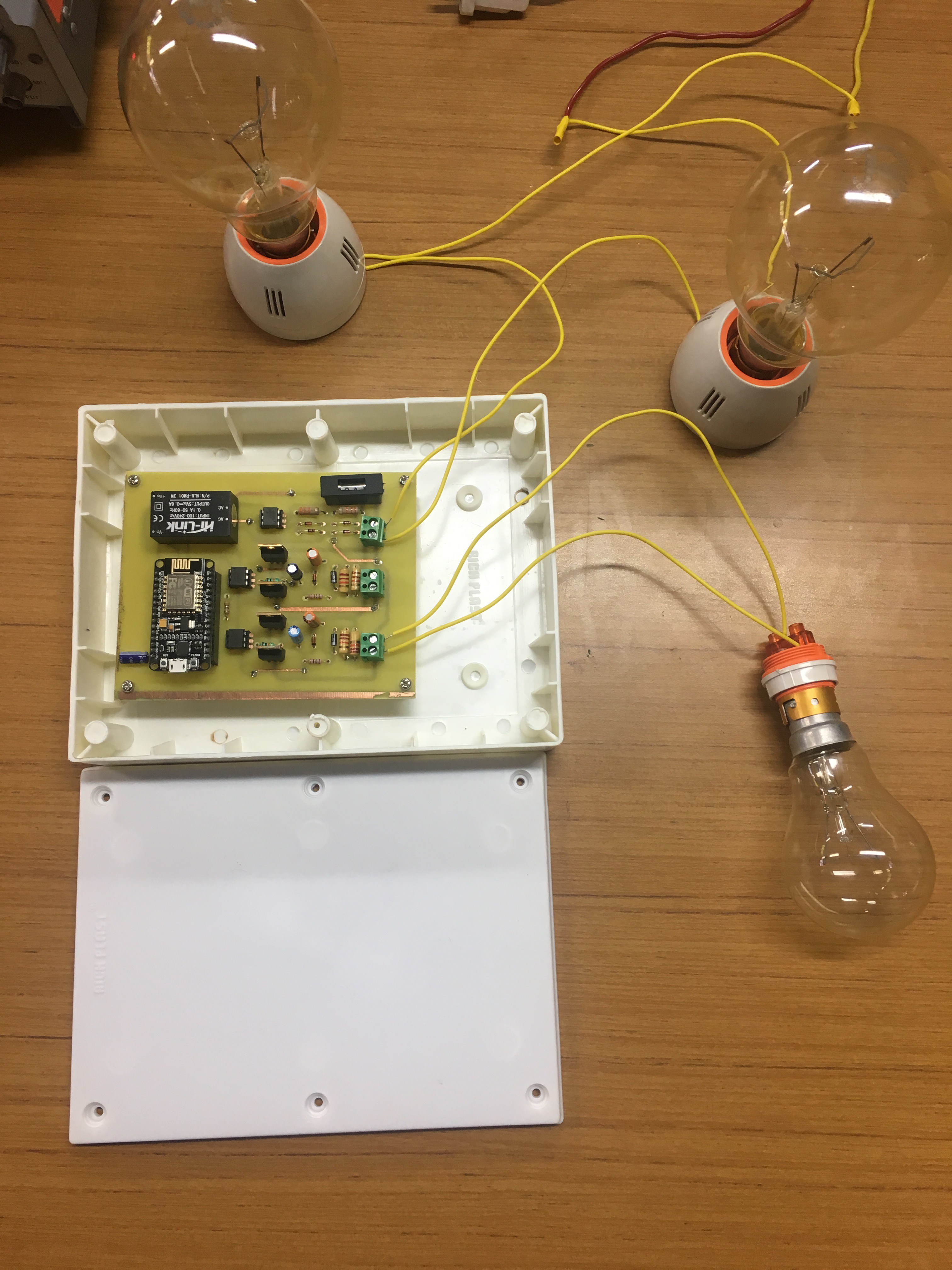
Now that the PCB is ready it is extremely important to take the following precautions before testing the module for the first time (Don't be overwhelmed have some patience!!!)
- Adding 2 - 200W bulbs in series with the test circuit (between the mains power supply and the input terminal of the module) as shown in the image.
- Covering the PCB with plastic encasing.
- Please use mounting screws for the PCB.
- Cover your eyes with glasses to prevent any accidental damage.
Now you are ready to test the design safely,always remember SAFETY FIRST,especially for newbies..
(Henceforth, you may remove the series bulbs and test the pcb directly from mains supply)
If things go fine you have successfully made a dimmer module, Congratulations!!!
Else check your soldering work again with a DMM.
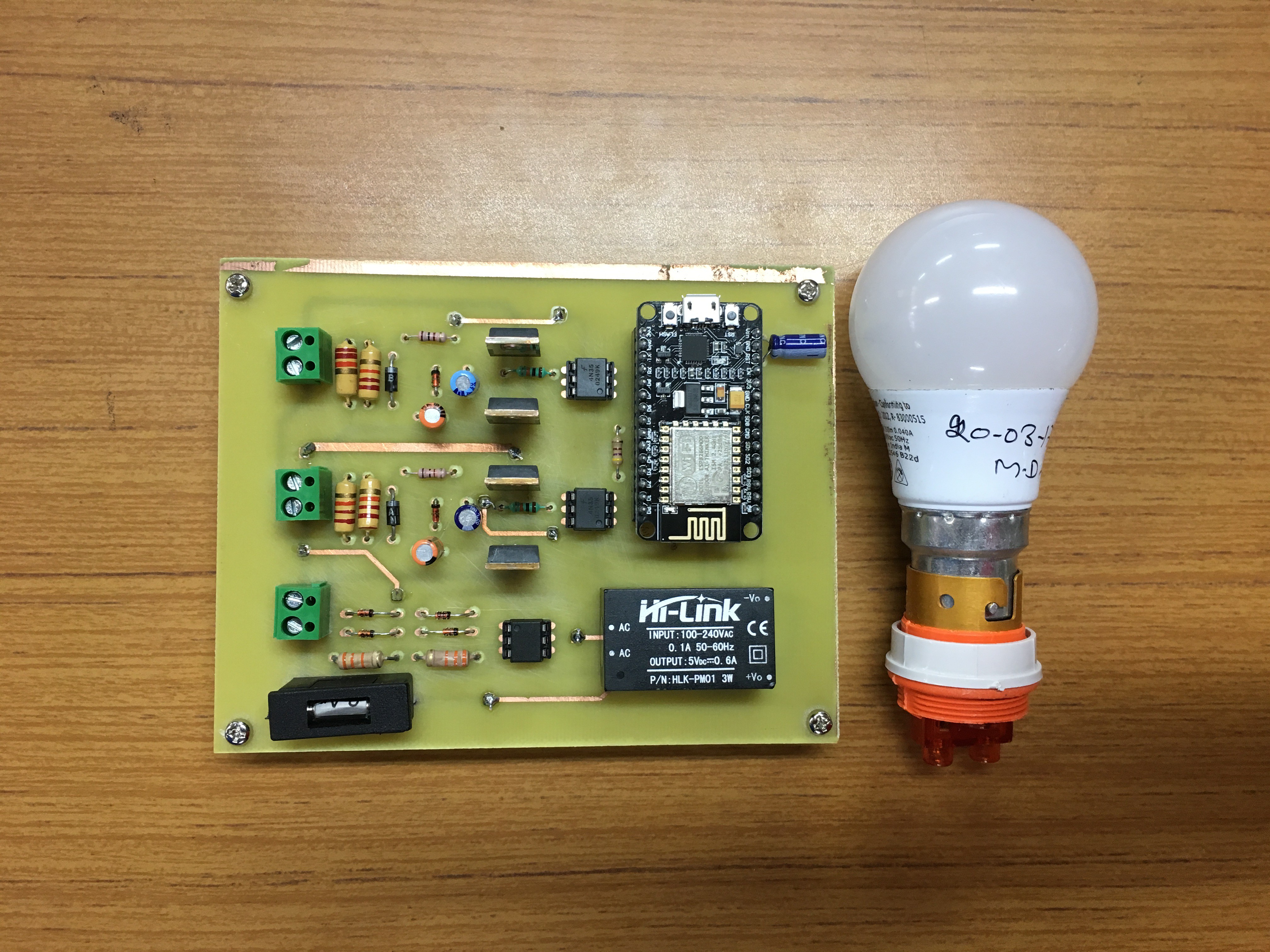
Final Product!!
The finished Dimmer module can be used to control the ambience of your room conveniently.
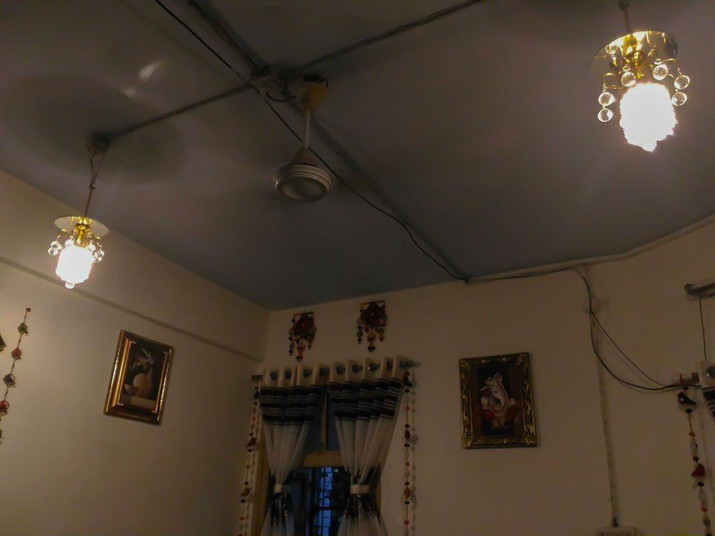
I have added some videos to demonstrate/explain working of the prototype and an image showing it's installation in my home.
Now it's time to make yours!!!
If you happen to do some creative work do let me know.