Bruce Land
Simulated visual system
We want to use artificial neural systems to teach biological
instrumentation methods. The goal is a set of small circuits which
behave like neural systems with respect to voltage, timing, and system
behavior. This will enable students to exercise their skills in setting
up amplifiers and oscilloscopes, getting rid of noise, connecting to a
computer and writing software , while concentrating on the electronic
technology, rather than the biological technology. We believe that
modeling is no substitute for work with real animals, but modeling can
help in understanding electronic and logical concepts before the
students use real animals.
We built a simple model of an array of light sensors with the following properties:
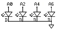
- The light sensitive elements are LEDs being used in a
photovoltaic mode. The voltages produced by the LEDs are digitized by
the microcontroller. Each positive lead of each LED is connected to a
ADC channel (0,2,4,6). The negative leads are all grounded. The
schematic is shown below.
![]()
- Sensor output is proportional to light intensity, but has a highpass characteristic which simulates accomodation to a fixed light level. The highpass filter is simulated on the microcontroller.
- The sensor outputs go to integrate-and-fire (IF) neurons which are simulated on the Atmel mega32 microcontroller.
- There are four sensors and four IF neurons. Each sensor excites its respective neuron, and inhibits the neurons on each side This simulates lateral inhibition. The equations for this are given below.
- Each neuron has a different amplitude and duration action potential output so that the neurons can be distinguished. The outputs may be made the same to make analysis more challanging.
- All four digital spike trains are summed together in the microcontroller, as if the student were recording from a nerve containing all four axons.
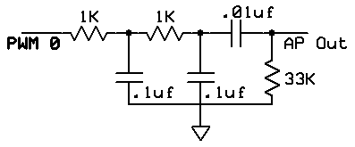
- The digital spike train is modifed by an analog highpass/lowpass
filter to more closely resemble real extracellular recordings. The pulse
train output from the microcontroller was shaped using the following
circuit. The two lowpass sections surpress the 62,500 Hz PWM artifact
and limit the rise rate. The highpass section produces the undershoot at
the end of the AP. The final version will probably have a voltage
divider added to the output to make the amplitude a few millivolts.
![]()
The Codevision C program running on the Mega32 microcontroller consists of three parts:
- Initialization
sets up
- PORTA for analog input and sets up the A/D converter for lef-justifed read using the internal Vcc reference.
- PORTB for pulse width modulator (PWM) channel 0 output. This allows D/A output.
- Timer0 to run the PWM at 62,500 samples/sec. The fast PWM cycle helps with filtering out PWM noise.
- Timer1 to interrupt every 2048 cycles (about 7800 Hz) to update the neuron dynamics and the PWM value.
- UART for debugging
- Turns on interrupts
- The timer interrupt
- Updates the integrate-and-fire neuron voltage.
For speed, all operations were done in 16-bit integer arithmetic, using only add, subtract and shift operations. Multiplies are too slow. The equations were scaled by multiplying by 64 to avoid fractions. For the 4 cells the voltages updates were
v[0] = v[0] - (v[0]>>6) + (neuronInput[0]<<gain1) - (neuronInput[1]<<gain1) ;

      v[1] = v[1] - (v[1]>>6) + (neuronInput[1]<<gain1) -
(neuronInput[0]<<gain2) - (neuronInput[2]<<gain2) ;

      v[2] = v[2] - (v[2]>>6) + (neuronInput[2]<<gain1) -
(neuronInput[1]<<gain2) - (neuronInput[3]<<gain2) ;

      v[3] = v[3] - (v[3]>>6) + (neuronInput[3]<<gain1) - (neuronInput[2]<<gain1) ;
and the inputs are scaled up to account for the factor of 64. Nearest neighbor inputs were subtracted so that uniform illumination produced no output. The>>6corresponds to a membrane time constant of a few mSec. The indices refer to cell number. - Detects threshold crossing and forms action potentials and
refractory periods by counting the number of clock ticks which have
pasted after an threshold event. The action potential amplitude of each
neuron is set to a different number so that each one will appear
different height on a scope. The refractory period is set to about 10
mSec. The threshold may need to be adjusted 20%, depending on the exact
LEDs which are used.
// detect threshold crossing if (v[i] > threshold ) begin // set the amplitude, duration, refactory period ap[i] = 50+(i<<3) ; apDur[i] = 2 ; apRef[i] = 80+(i<<3); end // AP duration counter if (apDur[i] > 0) apDur[i] = apDur[i] - 1; else ap[i] = 0; // refractory period counter if (apRef[i] > 0) begin apRef[i] = apRef[i] - 1; v[i] = 0; end - Forms the composite action potentials by forming the sum of AP amplitudes and setting the PWM control port to this value
OCR0 = ap[0] + ap[1] + ap[2] + ap[3]
- Updates the integrate-and-fire neuron voltage.
- Main program loop
- Reads 4 A/D channels.
Red LEDs respond to room-light by producing a voltage of between 100 mV and 2 Volts, with a value roughly proportional to intensity. This voltage range fits well with the Mega32 A/D converters which were set up to take 0 to 5 volts. - Highpass filters the inputs.
For the sensor highpass operation, a basic one-pole digital filter was used to produce a lowpass average, which was then subtracted from the current input. The basic equations were
lowpass(n) = (1-a)*lowpass(n-1) + a*input(n) with a=1/32

neuronInput(n) = input(n) - lowpass(n)
However some manipulation had to be done before these were suitable for real-time operation. Since we are using integers, there is no way to represent 1/32 or to multiply by a fraction. To handle this, the entire first equation was multiplied by 32 so that
32*lowpass(n) = 32*lowpass(n-1) - lowpass(n-1) + input(n)
The quantity stored between updates is32*lowpass(n)=scaledLowpassso the equations become
scaledLowpass(n) = scaledLowpass(n-1) - (scaledLowpass(n-1)>>5) + input(n)
neuronInput(n) = input(n) - scaledLowpass(n)>>5)
where the>>5operator divides the value by 32 by shifting. Delays for a few millseconds.
This delay time effectively sets the time constant of the highpass. I chose about 0.25 seconds as the time constant by setting the delay to 5 mSec.
- Reads 4 A/D channels.
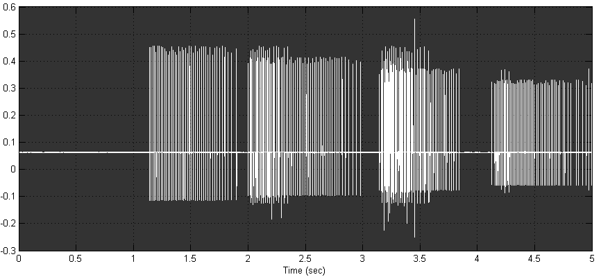
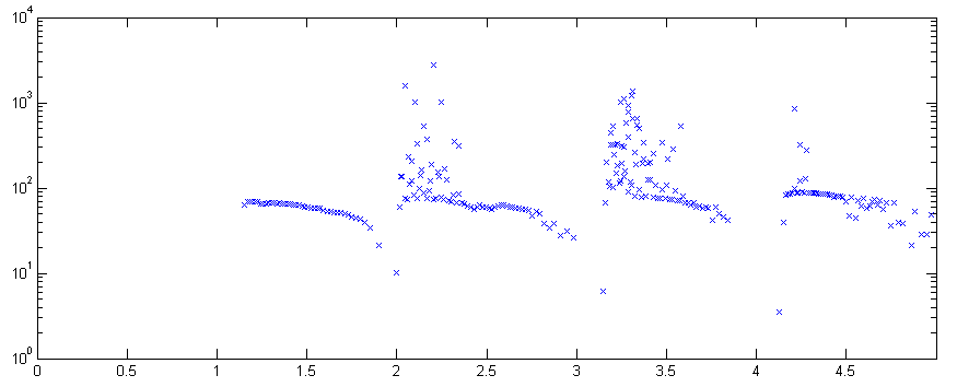
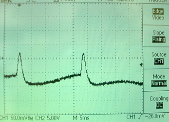
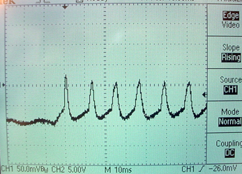
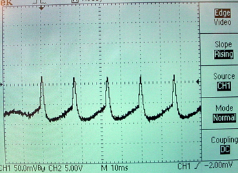
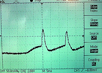
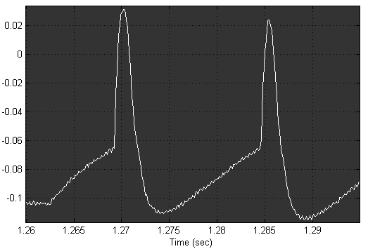
If we monitor this program using the audio input of a computer and the Matlab DAQ toolbox, we can write a program
 to record spikes. The following images show the results of sweeping a
light over the four photosensors. You can see the different amplitudes
of units and the approximately exponential fall of spike rate in the
second image.
Simulated action potential
Intracellular recording model using a state machine
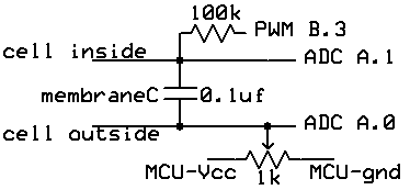
We built a dynamic clamp using a Atmel Mega32 microcontroller (MCU) to produce realistic current flows into a passive membrane capacitance.
The circuit is shown below. There are two external connections, as
there would be in a real cell. The MCU reads the differential voltage at
A.1 and A.0 (membrane voltage) to control conductances. All
voltages are produced by varying the current coming from the timer0 PWM
output. The potentiometer is adjusted to make a resting potential
of -90 mV. The potentiometer setting acts as the reference voltage for
the ADC and for the external connections. Note that MCU ground must be
isolated from the box that contains the circuit so that the external
ground reference is the cell outside lead.
ntracellular recording model using modified Hodgkin-Huxley model
The circuit is the same as in the previous section and the potentiometer is adjusted to a resting potential of -90 mV. The program uses the following model:
- The HH state variables V, m, n and h are simulated, with a few simplifications. The voltage dependency of steady state variables and their time constants is reduced from exponential form to a simple on/off, fast/slow form.
- State variable m is assumed to vary rapidly, but n and h follow first order kinetics. so that
m = m∞

    h = h + (h∞-h)*dt/τh

n = n + (n∞-n)*dt/τn - The steady state values of
m∞, h∞andn∞switch between two states. They are each either one or zero depending only on the membrane voltage. Them∞andn∞values go to one when depolarized. Theh∞value goes to zero when depolarized. - The time constants
τhandτnare either fast or slow depending only on the membrane voltage. They are fast when the membrane is depolarized. - The sodium conductance is written as
Gna=maxGna*m*h. Sincemis either one or zero it makes no sense to raise it to a power. - The potassium conductance is written as
Gk=maxGk*n4. - The ionic current feeding into the real membrane capacitor is then
Gna*(v-Ena) + Gk*(v-Ek)
plus any injected current for testing.
All arithmetic is done in 8:8 fixed point. Voltages are scaled so that the integer part of the fixed point number is mV/4. The model is updated 7800 times/sec.
Below are some traces at different levels of constant current injection.
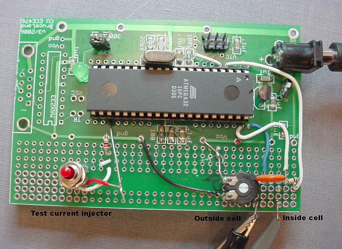
A slightly modified version of the program has somewhat slower h and n
dynamics and runs on the standalone board. An action potential and the
board are shown below. The resting potential adjusting trimpot is in the
lower right, next to the membrane capacitor. There is a button to the
lower left to inject a test current.
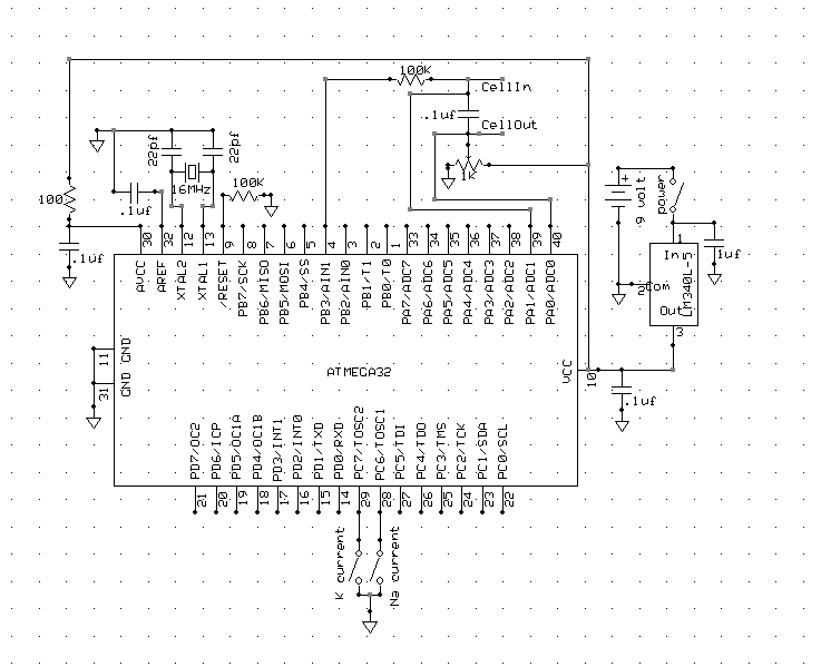
The full schematic is below. Note that ONLY two connections go to the outside world: CellIn and CellOut. Microcontroller ground must not be connected outside this circuit.
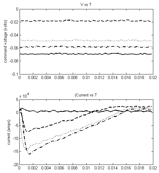
The following images are matlab figures under current clamp and
voltage clamp recorded using the National Instruments USB-6008
interface. The current clamp used a simple voltage follower for
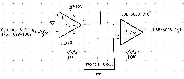
recording. The voltage clamp circuit is shown below. There were two
separate programs to make these images, one for current clamp and one for voltage clamp.

The voltage clamp circuit used is shown below. The command voltage
inverter (first opamp) is necessary because the USB-6008 can only
produce 0-5 volt output and this circuit required a negative clamp
voltage. The matlab program performed the operation
(Ch1-Ch0)/10000 = (V1-V0)/Rfeedback
to estimate current.
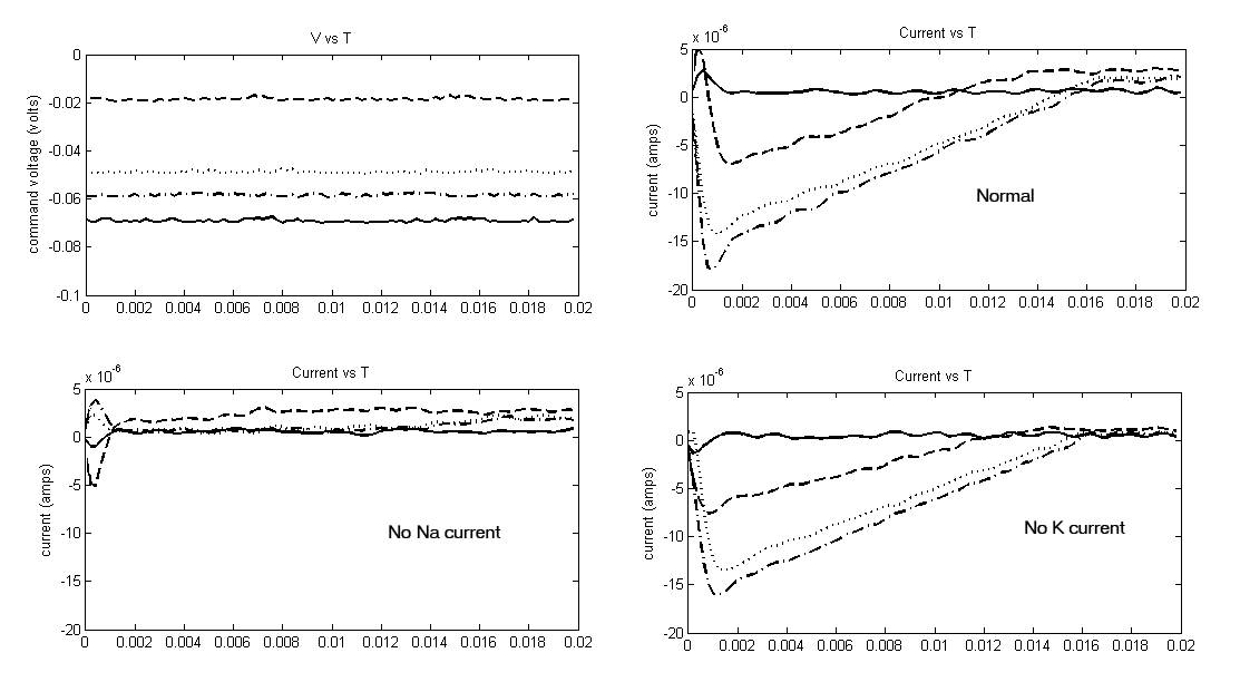
Individual conductances can be inactivated in this version of the program.
Shorting microcontroller pin C.7 to ground zeros the sodium current.
Shorting microcontroller pin C.6 to ground zeros the potassium current.
The next figure shows normal, suppressed soduim and suppressed
potassium current conditions. The voltage step occurs at time zero to
the value shown. Before the step, the volage was maintained at -100
millivolts.