 Hexabitz
What is it?
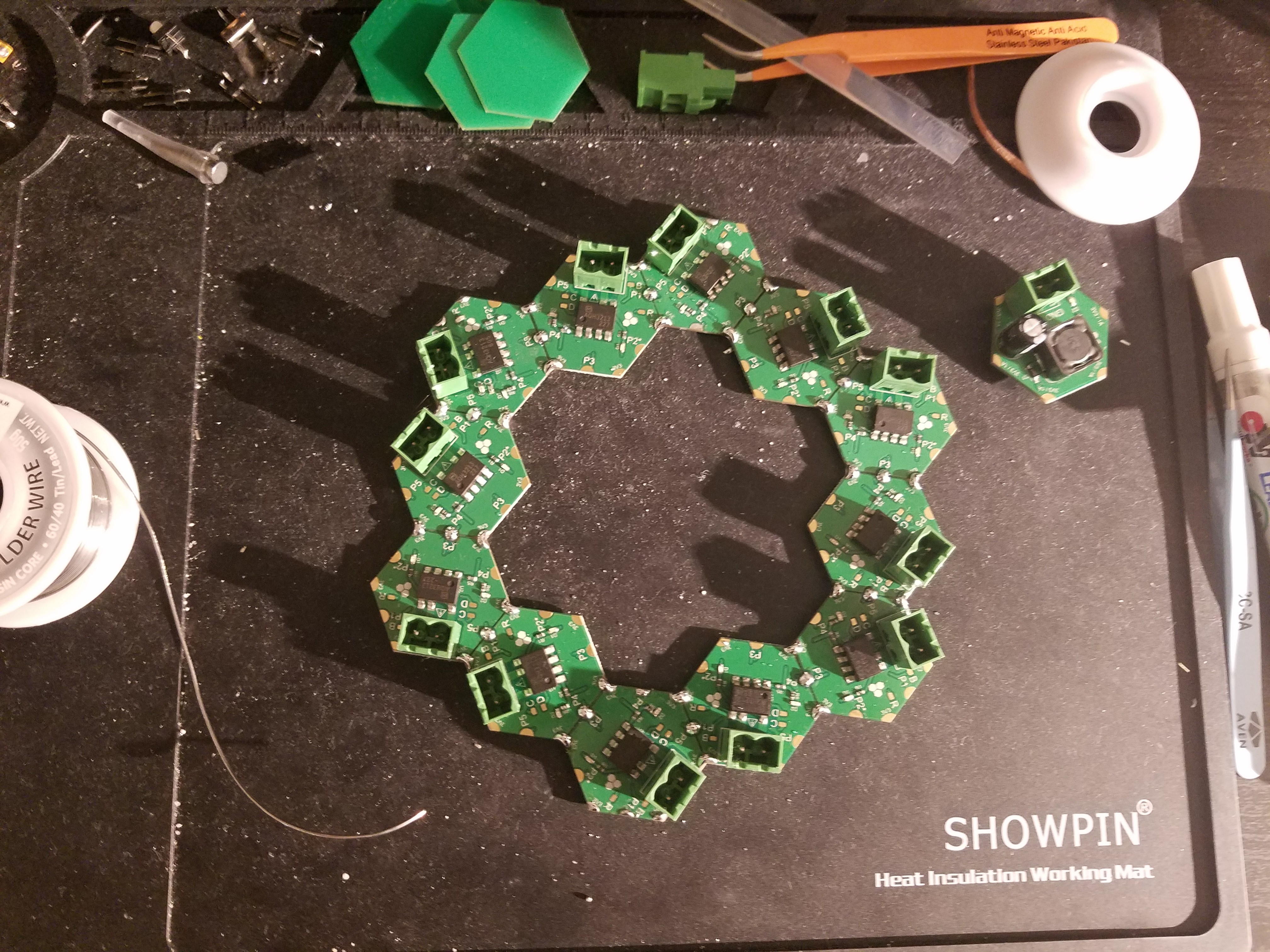
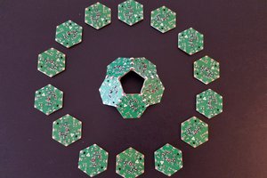
We will use the project to demo both the H09R00 Hexabitz solid state relay (SSR) module and the concept of building relatively large arrays and the way they can be automatically configured and controlled without writing code. 12 SSR modules are assembled in the first configuration and then the array is reconfigured into a different shape with only 10 SSRs. To make the system stand-alone, we also added a single 3.3V / 1A DC-DC module (H03R00) to power the modules themselves from a wall AC-DC adapter.
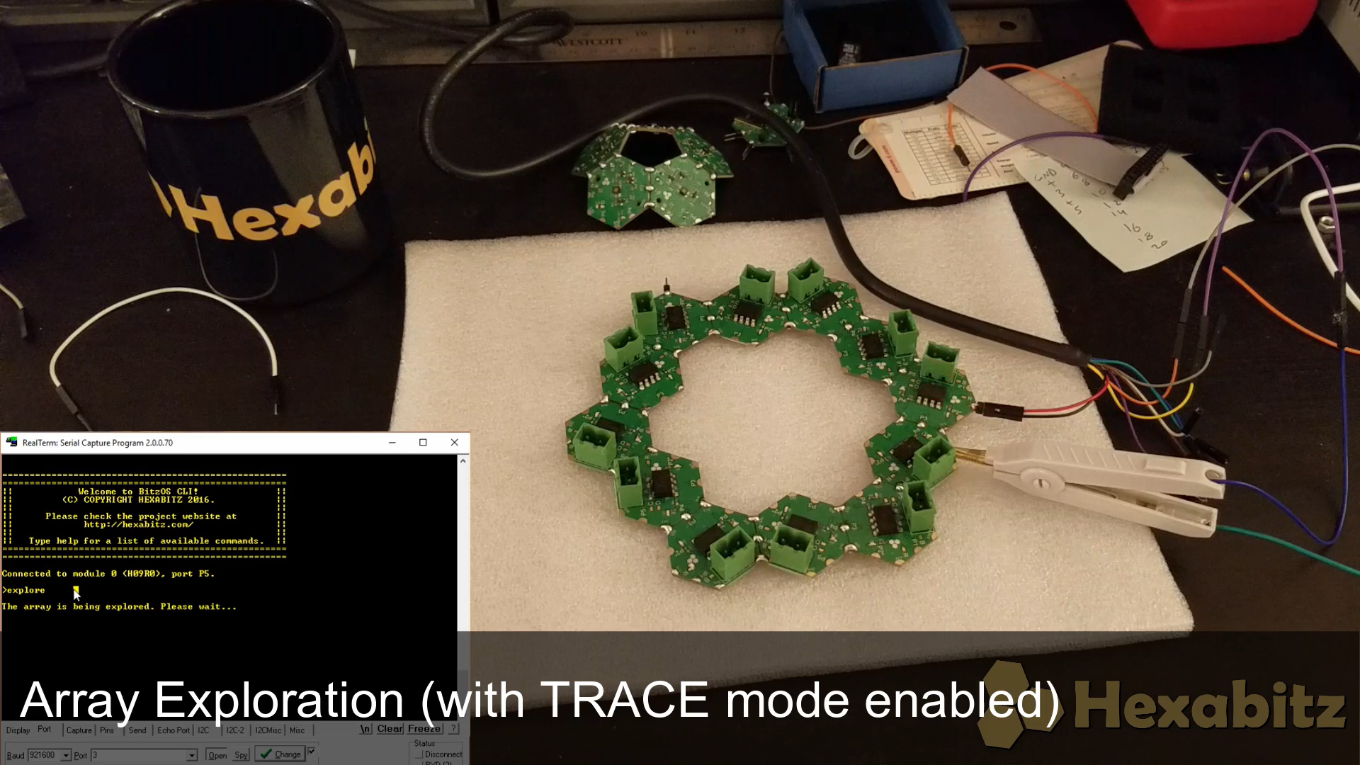
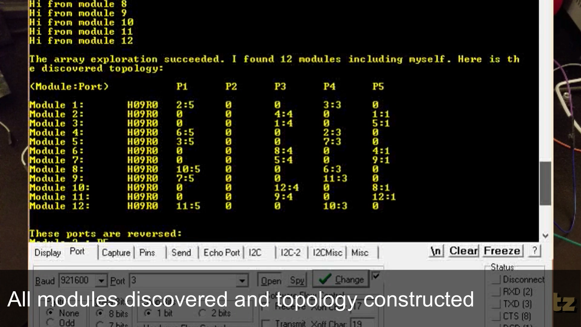
After the array is assembled, we demo a cool Command in Hexabitz CLIs: It is the automatic array exploration that allows modules to discover their neighbors and form their connections and routing table without you writing any code. After the array topology is explored and saved to non-volatile (MCU FLash) memory, the array can be used for its intended application. We show you single-cast, multi-cast and broadcast Commands that control only a single relay, a group or relays or all of them.
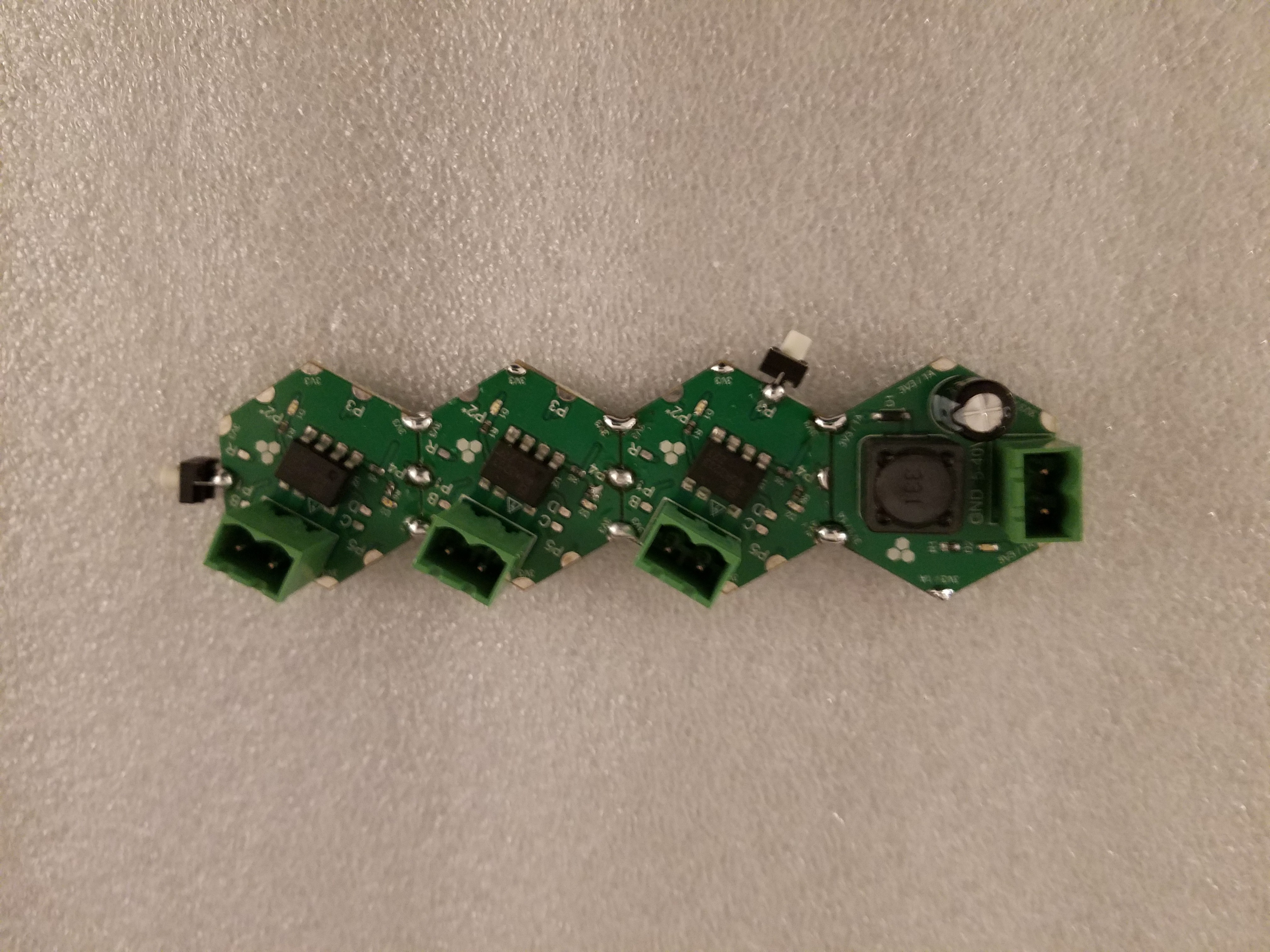
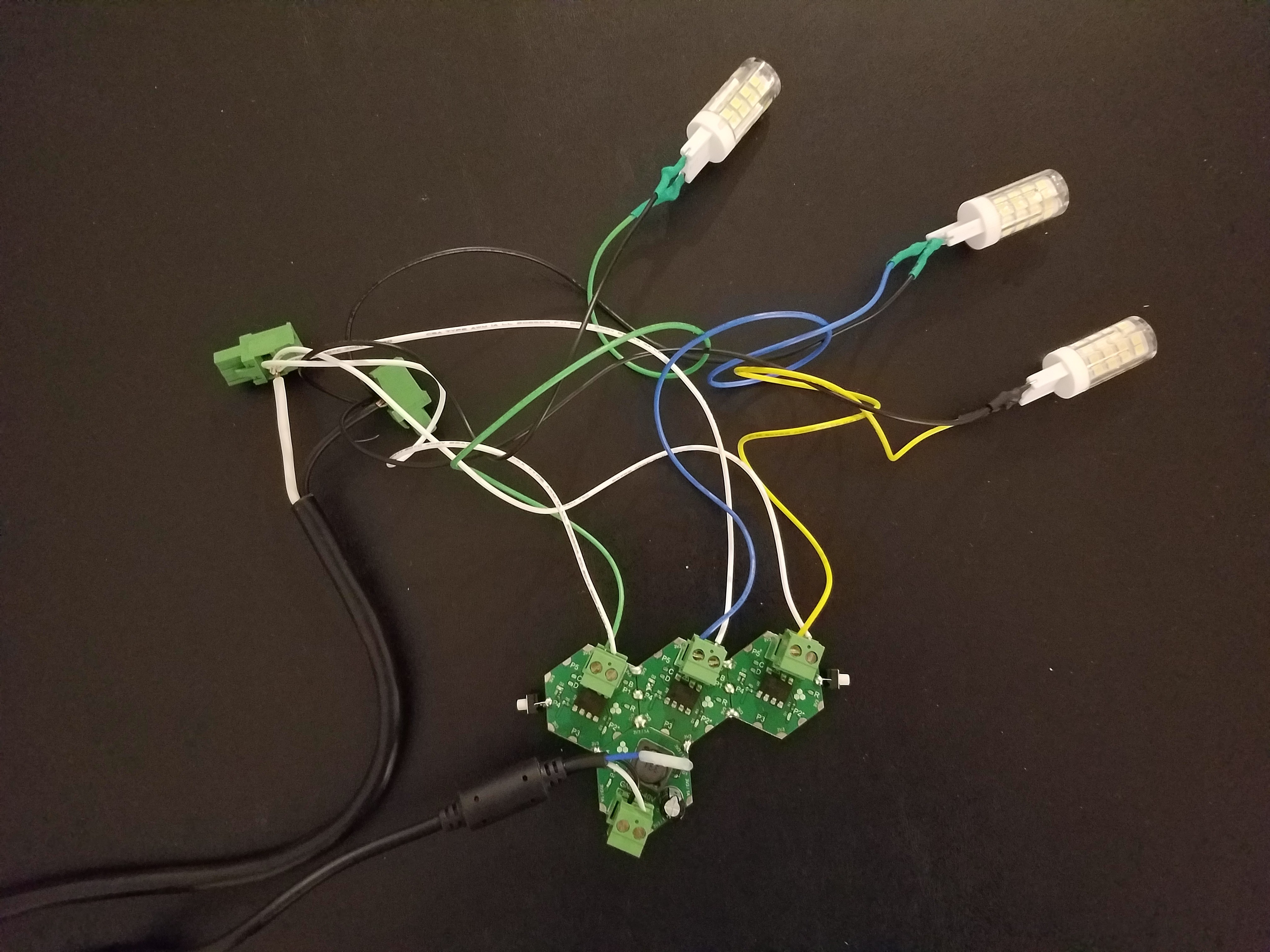
In the project logs, we test a smaller array of three SSRs and a single DC-DC module with a bunch of momentary tactile switches. We connect various AC loads to the relays: 120V AC LED lamps, an AC duct fan and an AC synchronous motor (usually used in microwaves!). Using the tactile switches we control these relays and their loads by toggling them ON / OFF or using the timeout functionality. We also show module PWM functionality modulating the relay and generating a variable RMS voltage.
Components:
- 12 x H09R00 Hexabitz Micro-SD Memory Card Module
- 1 x H03R00 Hexabitz 3.3V / 1A DC-DC Buck Power Module
- 2 x TL59FF160Q Momentary tactile push button
- 3 x 110V AC LED lamps
- 1 x 6" AC duct fan
- 1 x AC synchronous motor
Estimated hardware build time: 5-10 minutes
Estimated software development time: 5 minutes
Building And Configuring Arrays
First start assembling the relay modules in your preferred configuration. We chose this beautiful shape that fits 12 modules with all the green connectors (relay switch) on the outside perimeter. Add the H03R00 module is you are planning a stand-lone system. If not, you can power directly from your USB-UART cable!
Connect to one of the modules and run the CLI. We used the lovely modified Kelvin clamp to connect to the module array port! Once you call the explore command, module LEDs start dancing performing the complicated algorithm of finding neighbors, swapping ports, communicating their states and building the routing table. Once succeeded, the array topology and relevant information are stored to each module's MCU Flash so that whenever you power up again, all modules know their location and connections in the array.
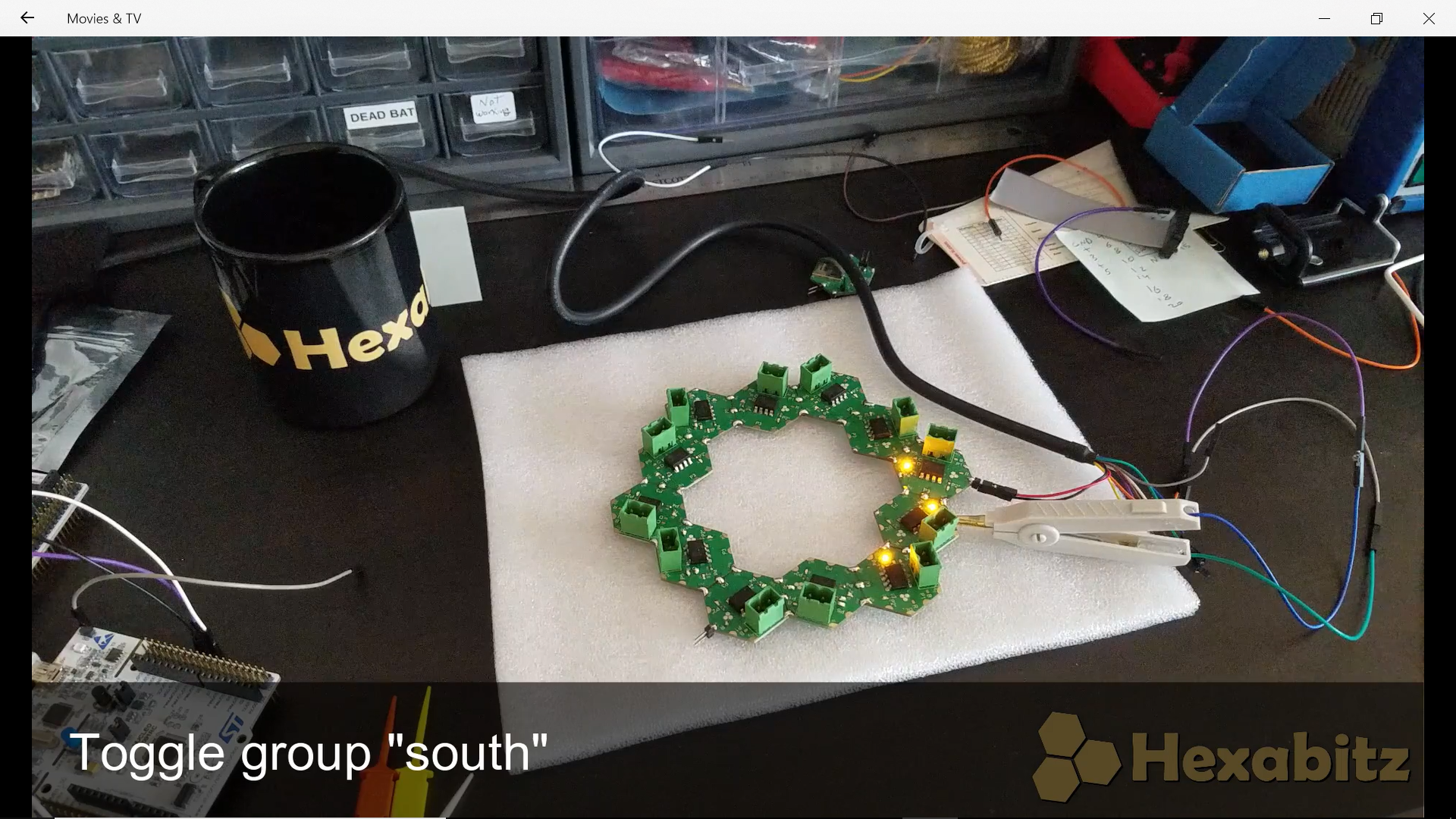
After that you can test everything works well with a broadcast command all.toggle. The yellow LEDs mean the relay output is turned ON, i.e., closed. The command was broadcasted to all connected modules and they toggled their output state from OFF to ON.
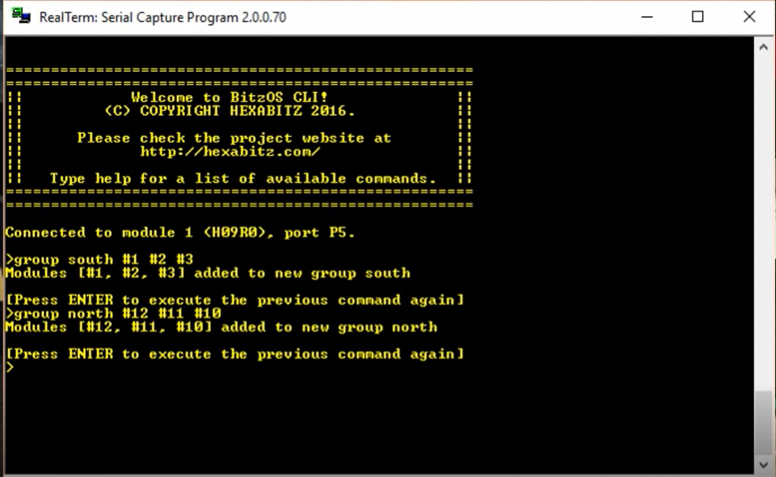
Modules can be grouped and given a name or alias as well. Commands can then be targeted only to the group members. Grouped module don't have to be adjacent or of the same type. You can for example, group all LEDs together and all relays together. Or you can group the relays driving the heaters in a group called heaters and the ones driving fans in a group called fans regardless of their physical location in the array. All you need then to control heaters and fans is to call them by name:
group heaters #1 #4 #5
group fans #2 #8
heaters.on
fans.toggle
Or split the relays into groups based on their load location: south room, north room etc.
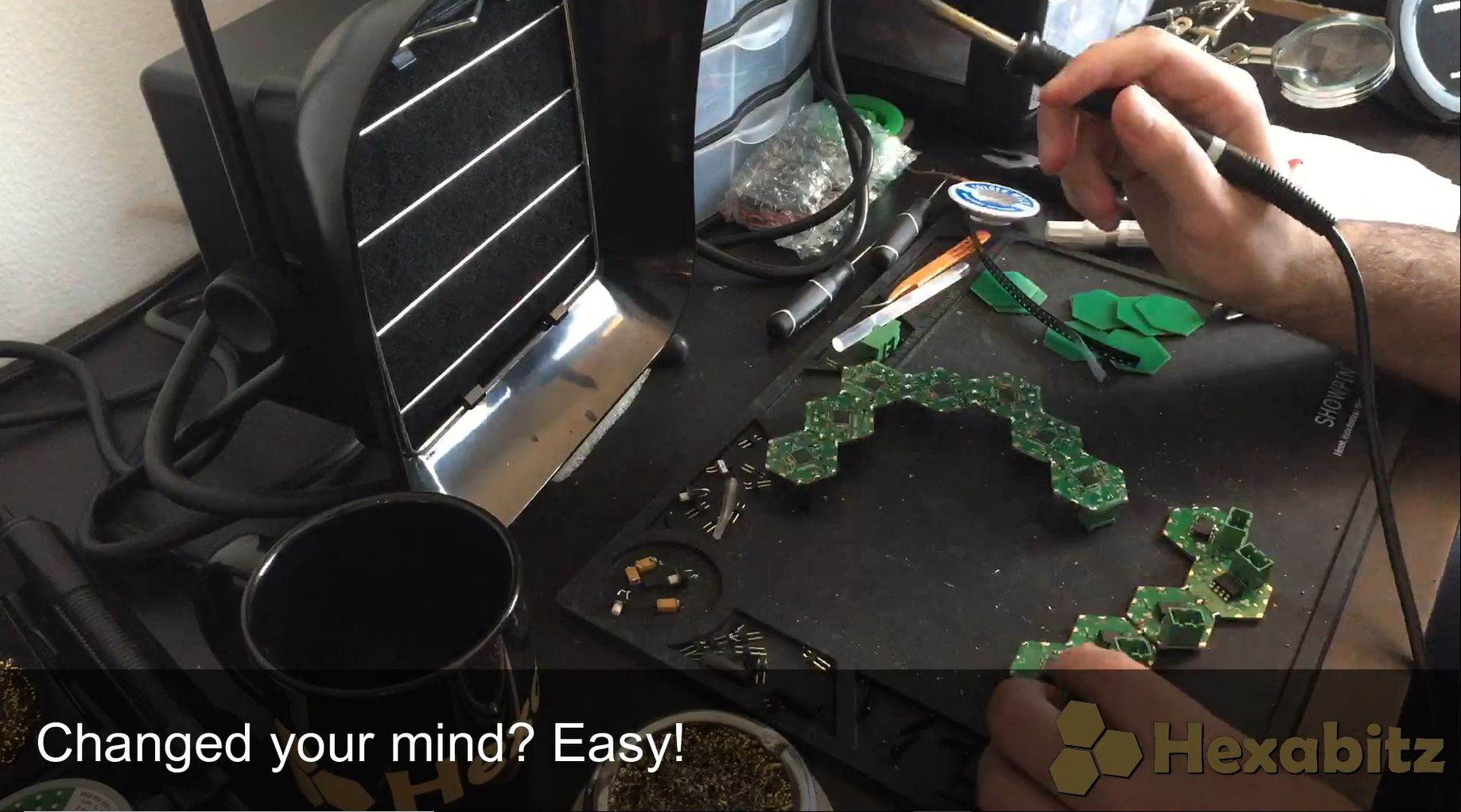
Can't decide what to build? Get twice the fun by disassembling the array and going into same process again for a completely different shape (and even quantity)! Before you disassemble the old array, make sure to erase the old topology from module non-volatile memory by executing the command:
default array
An here is your new...
Read more »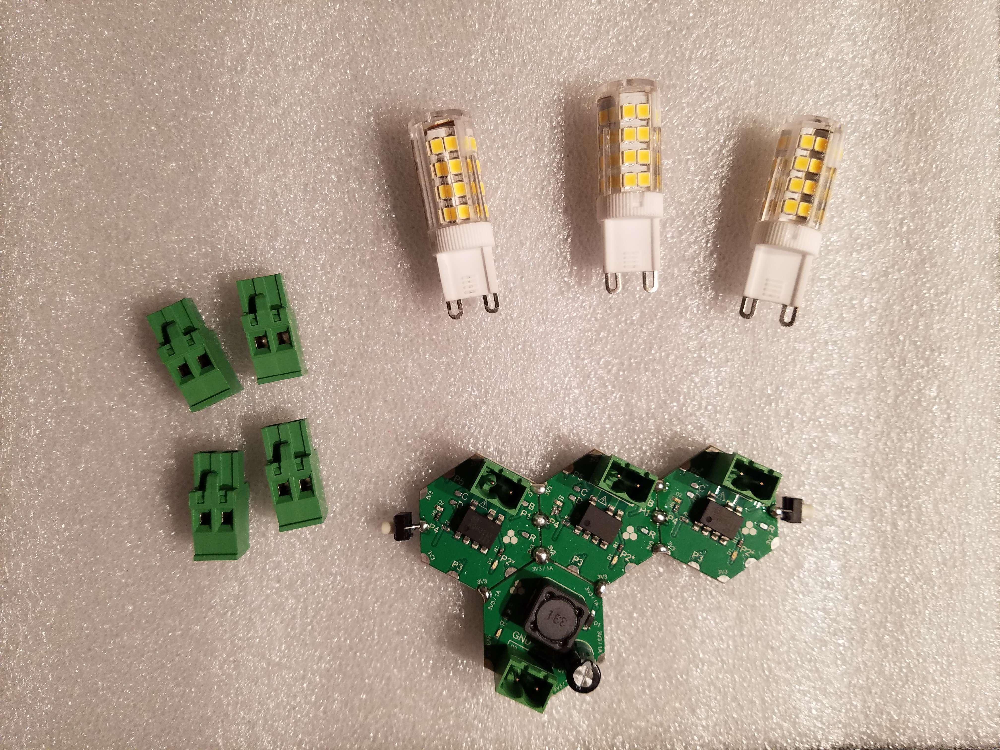
 Aula Jazmati
 Emilio P.G. Ficara
 Quinn
Quinn