The inspiration for this software came from Alexander Frank (http://www.changpuak.ch/electronics/Arduino-Shield-TOBI.php) who got it from Rich Heslip (http://rheslip.blogspot.com/2015/08/the-simple-scalar-network-analyser.html) who got his from PA2OHH (http://www.qsl.net/pa2ohh/11sa.htm). I made some pretty substantial modifications and in fact started over at one point but it's not my original idea so that's the history as best I know it.
I wrote it in Python 3 (using Anaconda, which contained most of the packages, except PySerial, which I had to download separately) . Here is a screenshot from my Network Analyzer running: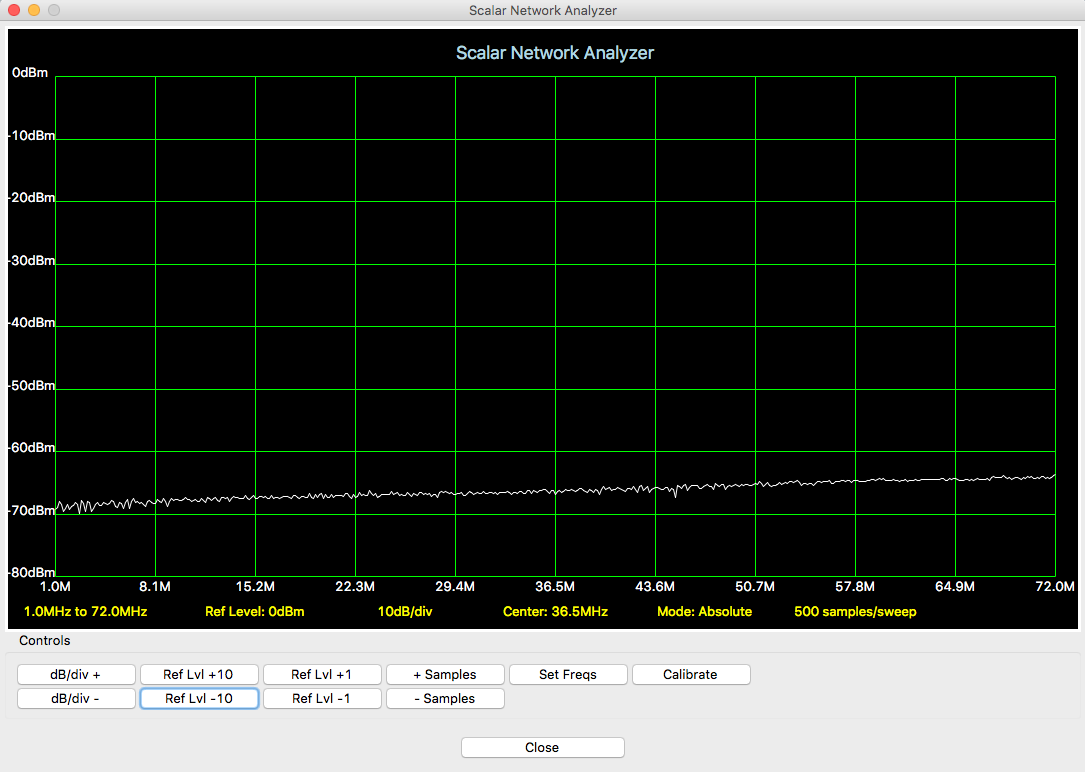 There is no option to select a port when it's running, you just have to know the port of your Arduino, edit the port name in the python file, then run the program.
Also, if you decrease the samples there's a chance it will stop running due to an array index out of bounds error.
All the controls are self-explanatory, I believe, with the exception of "Calibrate". When you click on Calibrate, it will complete a sweep at the current settings and save that trace as a reference. Ideally, this is done when you directly connect output to input. Then once the reference is created, connect the device under test to get a relative power reading. It moves out of relative mode back to absolute mode when either the frequency settings are changed or the number of samples per sweep are changed.
There are some magic numbers in the code where it converts from the ADC readings to power levels. I roughly calibrated the power detector by using my oscilloscope to observe the peak-to-peak voltage of the signal at the detector inputs, then converted those to dBm. I adjusted the potentiometer to lower the signal strength and made another observation. I plugged the readings into a spreadsheet and then did a best fit line to get the equation. That's where the magic numbers came from.
On the Arduino, the code is very simple. It parses a serial input for commands. If there is a number between 1 and 72,000,000, it sets the output frequency to that number. If it's anything else, it takes a power reading.
When taking a power reading, it reads the ADC 16 times, adds the conversion results together, then bit shifts right twice. This oversampling and decimating does two things: it averages out noise and it effectively adds two more bits to the converter (going from 10 bits to 12).
The sweep moves relatively quickly until the number of samples per sweep move up to 500 and 1000. At 1000 samples per sweep, it takes about 4 seconds to sweep the whole frequency range.
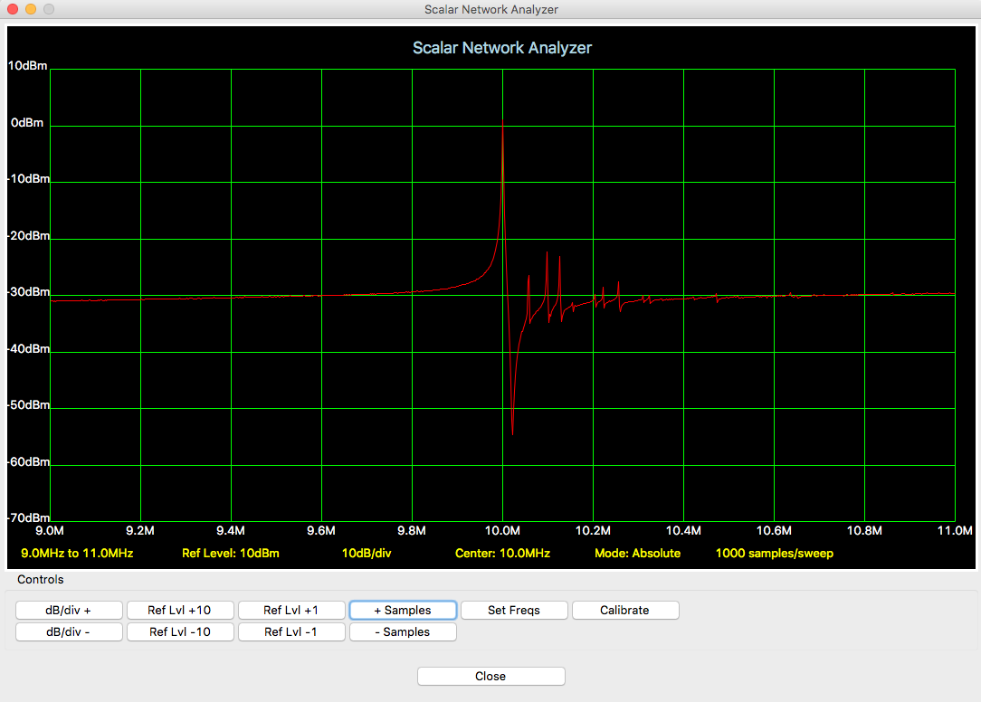
Here is a sweep of a 10MHz crystal on the Network Analyzer:
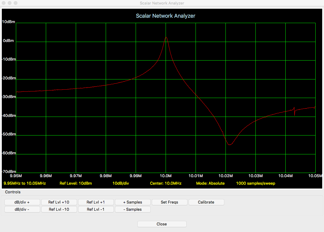
And here is a narrower sweep of the same crystal:
Look for the full Python and Arduino code in the files section.
Discussions
Become a Hackaday.io Member
Create an account to leave a comment. Already have an account? Log In.