There are several similar designs out there (most notably Alexander Frank's: http://www.changpuak.ch/electronics/Arduino-Shield-TOBI.php) which I only found after having designed my shield.
The AD9851 takes in a 30MHz reference clock which it multiplies by 6 to get its internal 180MHz clock. It takes I2C commands to control it's output frequency. It's a current output whose maximum current is set by a resistor. I went with a 3.92k resistor to give a max current of 10mA. My sine wave is then centered at 5mA and swings from 0-10mA.
I needed to filter out the aliased signal (basically 180MHz-desired output frequency) so I used a 7th order Butterworth LPF (because a flat passband is important here). I designed it for an input and output impedance of 100 Ohms. This way, the DDS sees essentially two 100 Ohm resistors in parallel (input and output resistors) giving a 50 Ohm impedance and converting my 0-10mA current into a 0-0.5V voltage swing. I was aiming for an output of 0dBm which is a 0.632V swing so I was a little short. I also wanted a buffer so that the DDS wasn't directly driving the output/load.
Enter the two transistor amplifier. It's a common emitter followed by a common collector with feedback. The design came for this came from Rich Heslip (http://rheslip.blogspot.com/2015/08/the-simple-scalar-network-analyser.html).
The schematic of my DDS/Filter/Amplifier is shown below: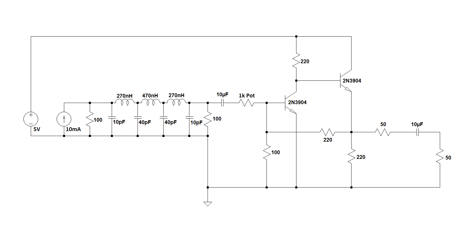 I added the 1K potentiometer to give some control to the output signal level. Turned up to 1K, the output is very small as it basically works as a voltage divider (it appears in series with the amplifier input impedance which is about 70ish Ohms). Turned down to zero, you get horrible distortion as the amplifier goes into saturation. In between though, you can finely tune the pot to give a nice 0dBm output sine wave.
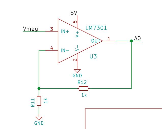
The input goes straight to a 51 Ohm resistor (no input filtering) to provide a broadband match. This means that the power detector is more sensitive to noise and such but also means it can be used as a power detector up to 500MHz. 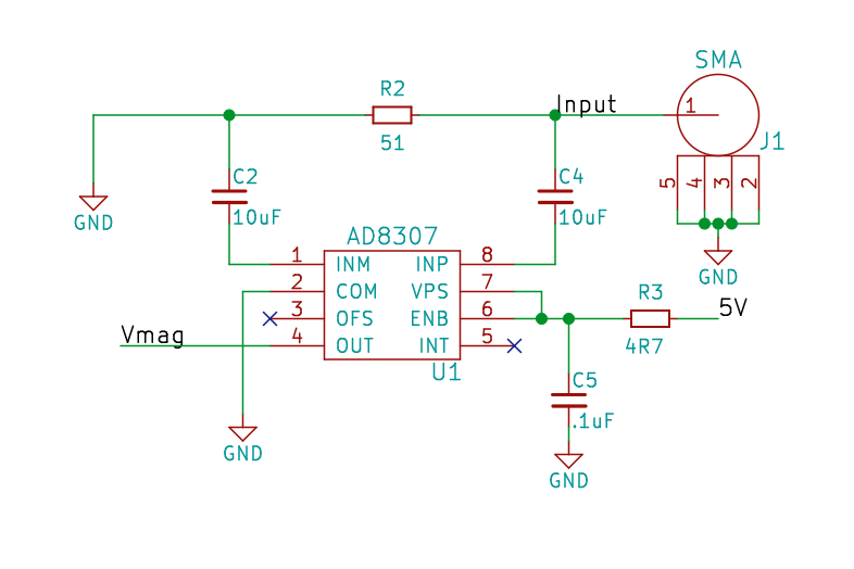 The output of the Analog Devices AD8307 (logarithmic power detector) goes to an Op Amp. This buffers the signal before it goes into the Arduino's ADC and also multiplies it by 2 so more of the ADC's range is utilized.
 Look for the complete schematic on the main project page in the files section.
I made the circuit on a four-layer board. RF traces run on the top layer and the I2C signals run almost entirely on the bottom layer. The board was made by Elecrow.
Elecrow did a great job and even though I only ordered five boards, they shipped me nine. All had been tested (I could see the probe marks on the pads). I think it was ~$25 for the boards and I paid the $20 for 3 day shipping (otherwise, it would literally take the slow boat from China). For around $50, I had nine four-layer boards that were 5cm x 5cm in my hands nine days after I clicked the button to submit my order.
Discussions
Become a Hackaday.io Member
Create an account to leave a comment. Already have an account? Log In.