 Robert
The main goal was to design heating bath temperature controller with as minimal overshoot as possible and good temperature control stability.
I made practically the same thing using a RaspberryPi and UniPi expansion board but it was a bit too complex and expensive. This solution might be a lot cheaper.
Requirements
- Temperature resolution of 0.1°C
- Temperature range 20-70°C
- Maximum overshoot < 0.5°C
- Temperature stability of +-0.1°C
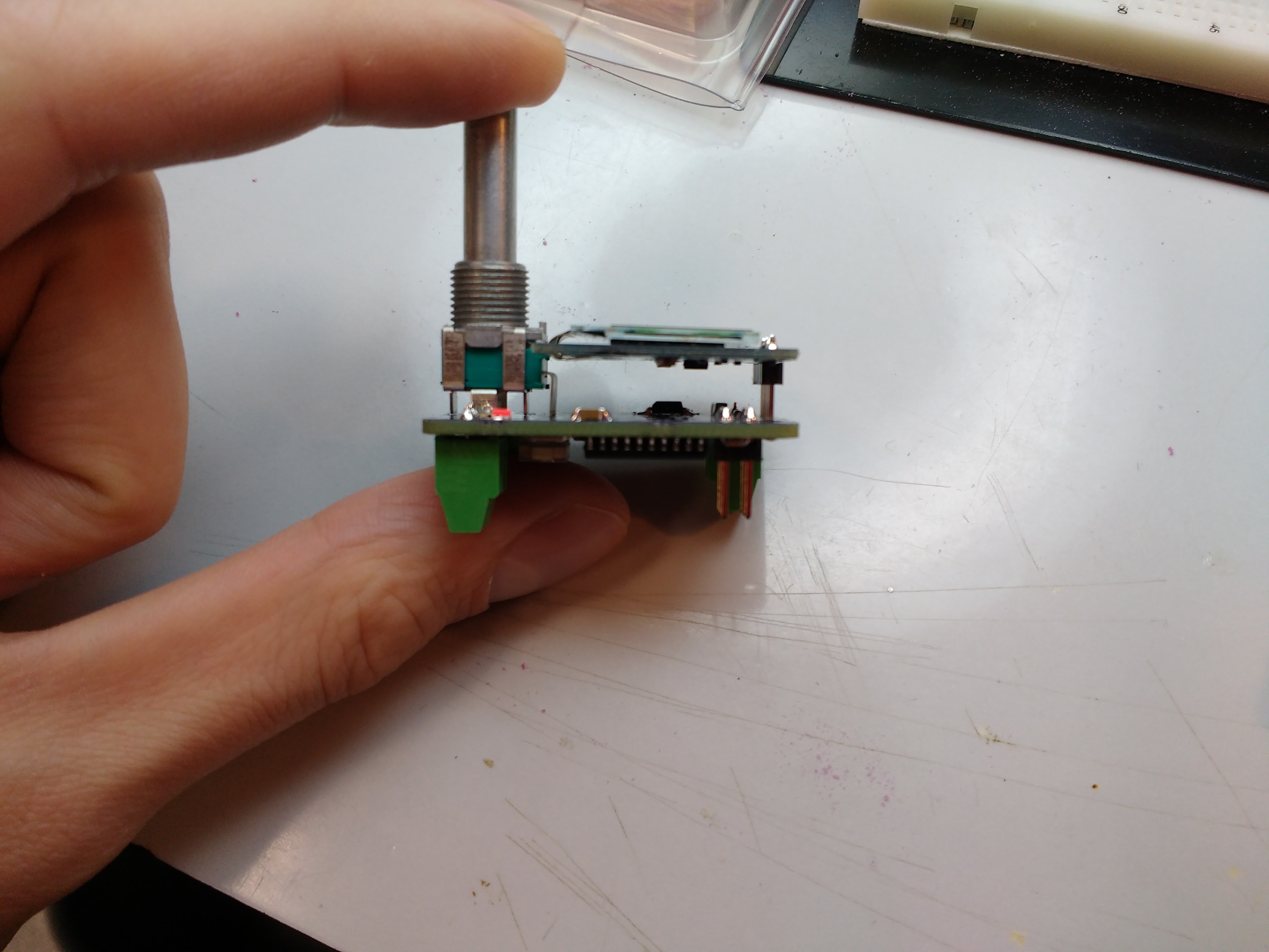
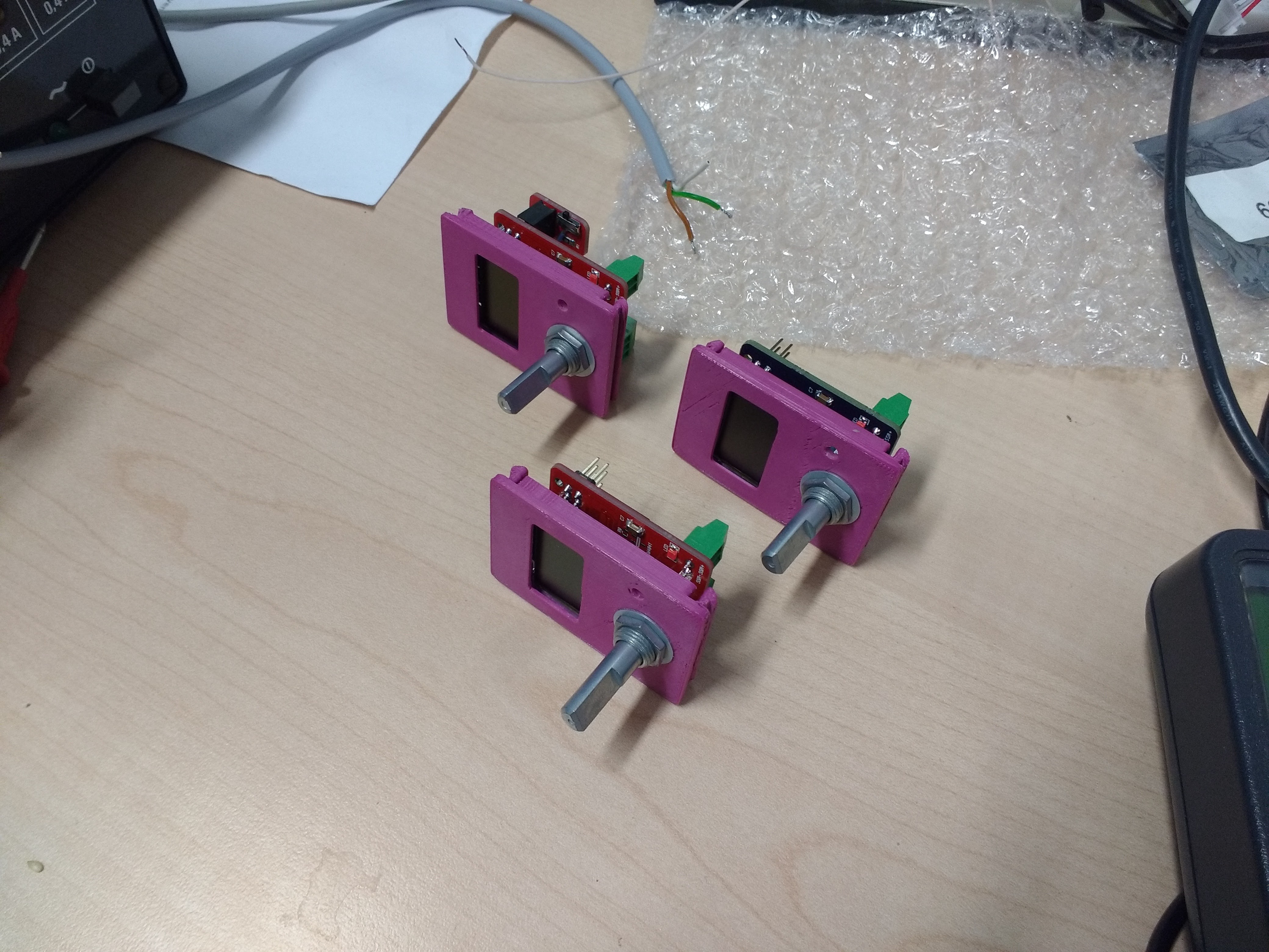
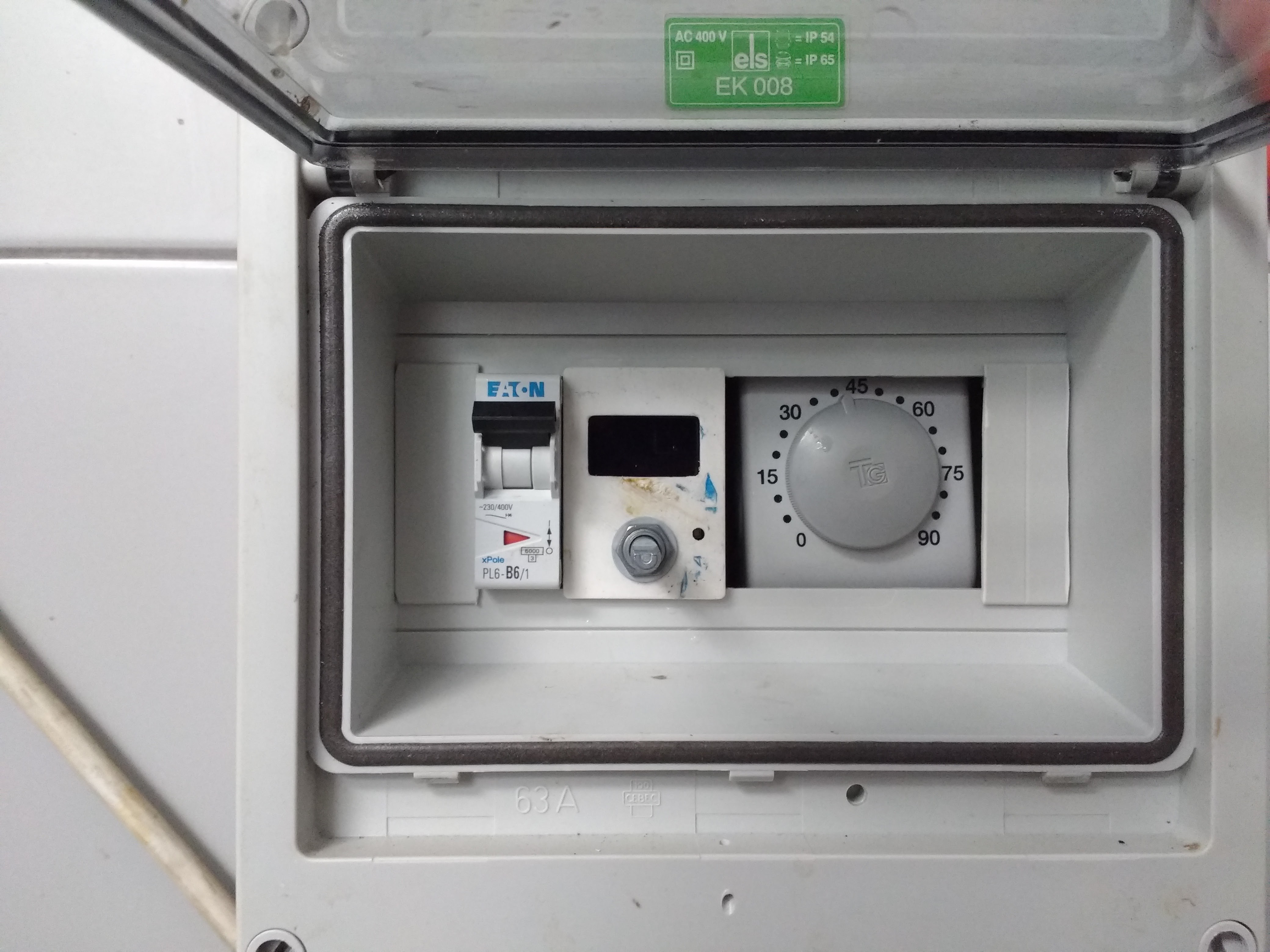
- To fit the regulator in fuse box two positions at max
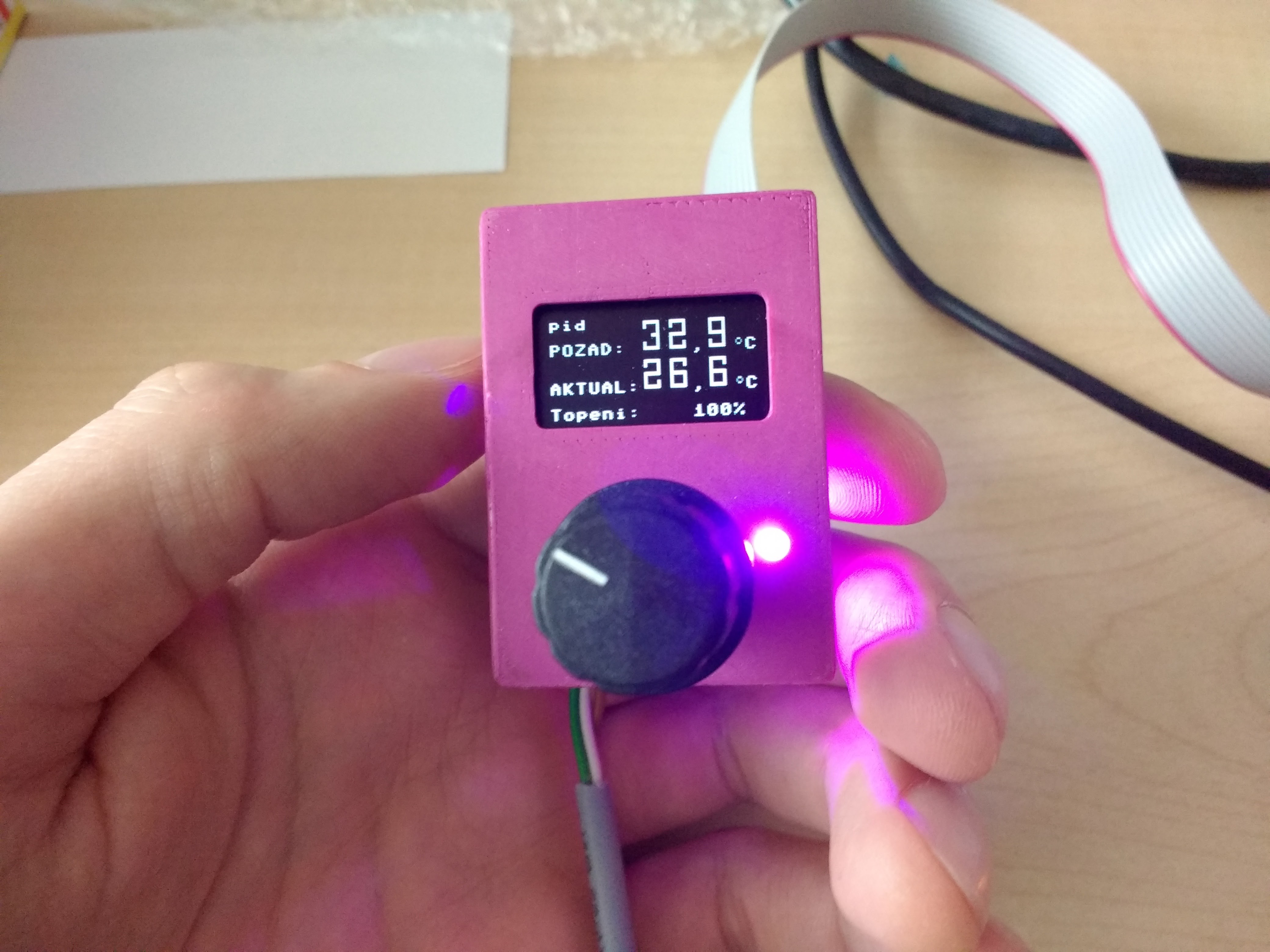
- Simple control with display
It is basicaly a Sous vide for sh*t :))
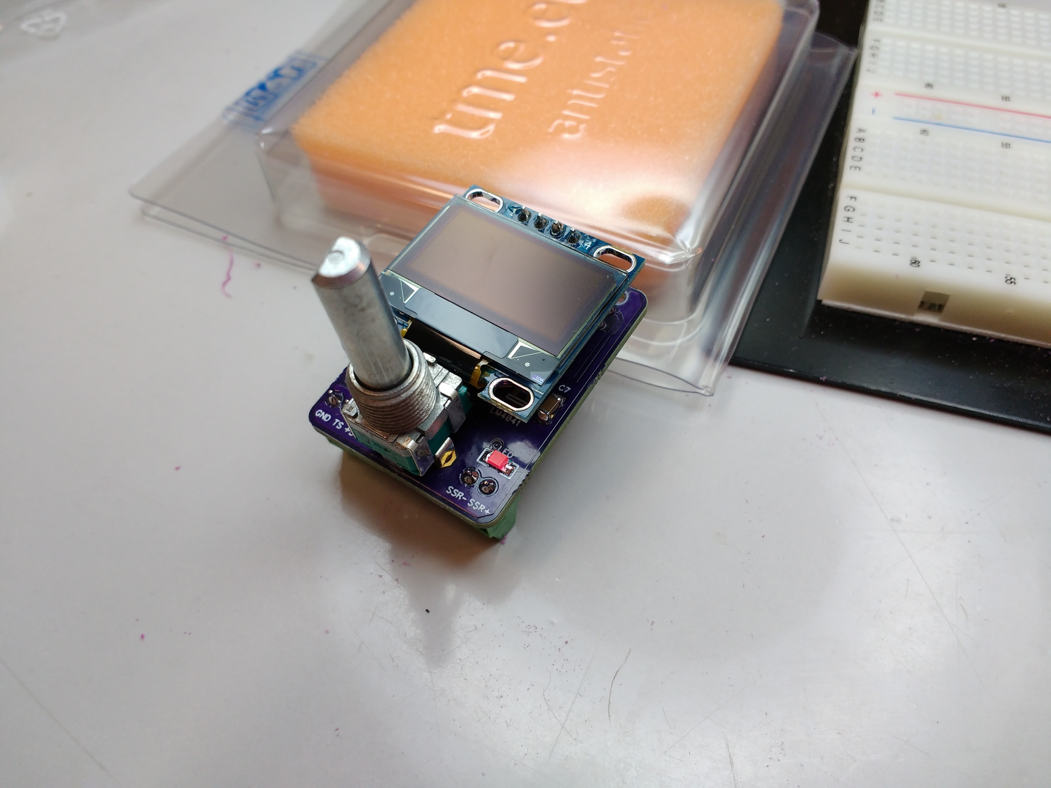
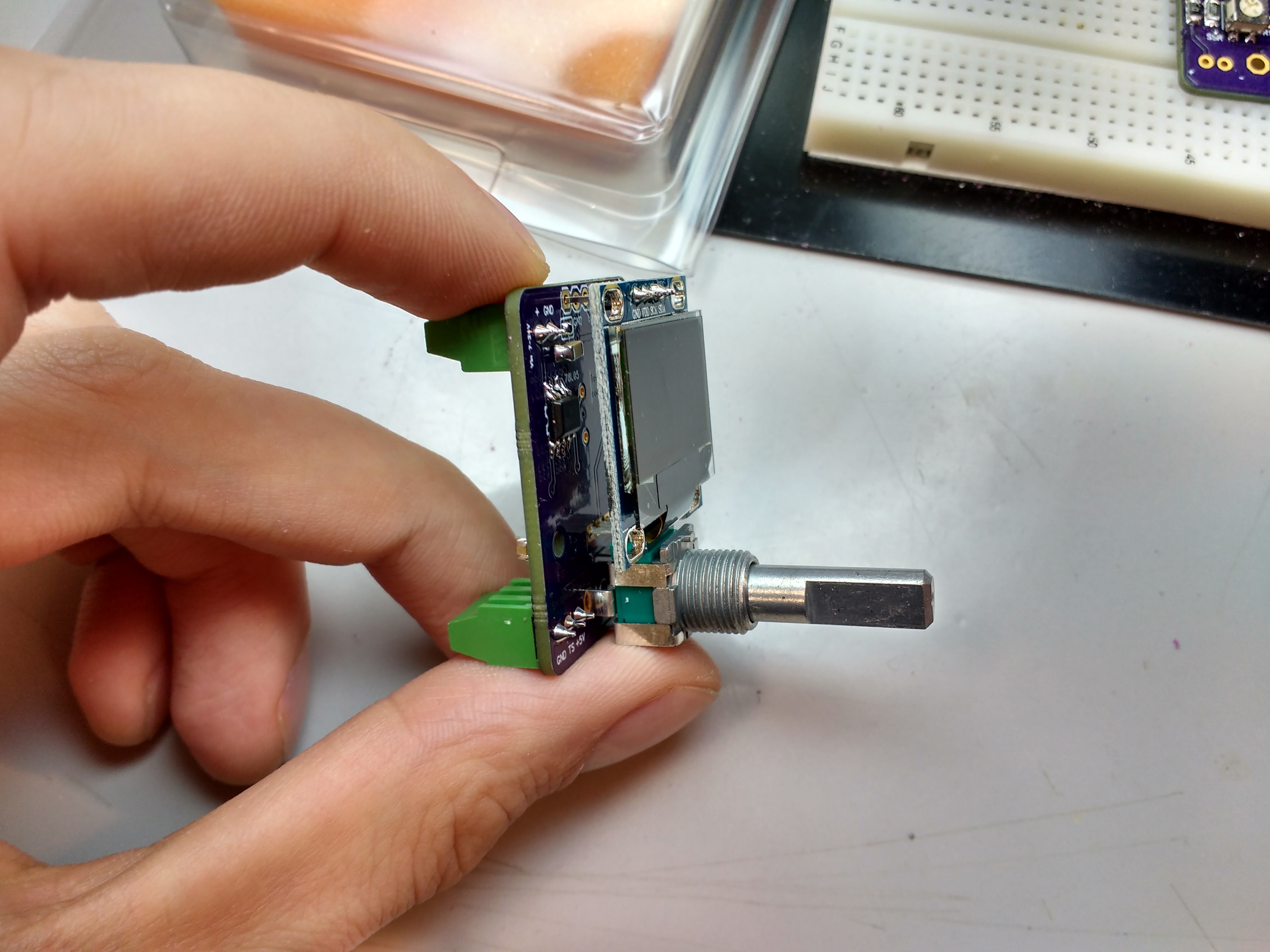
Main hardware components
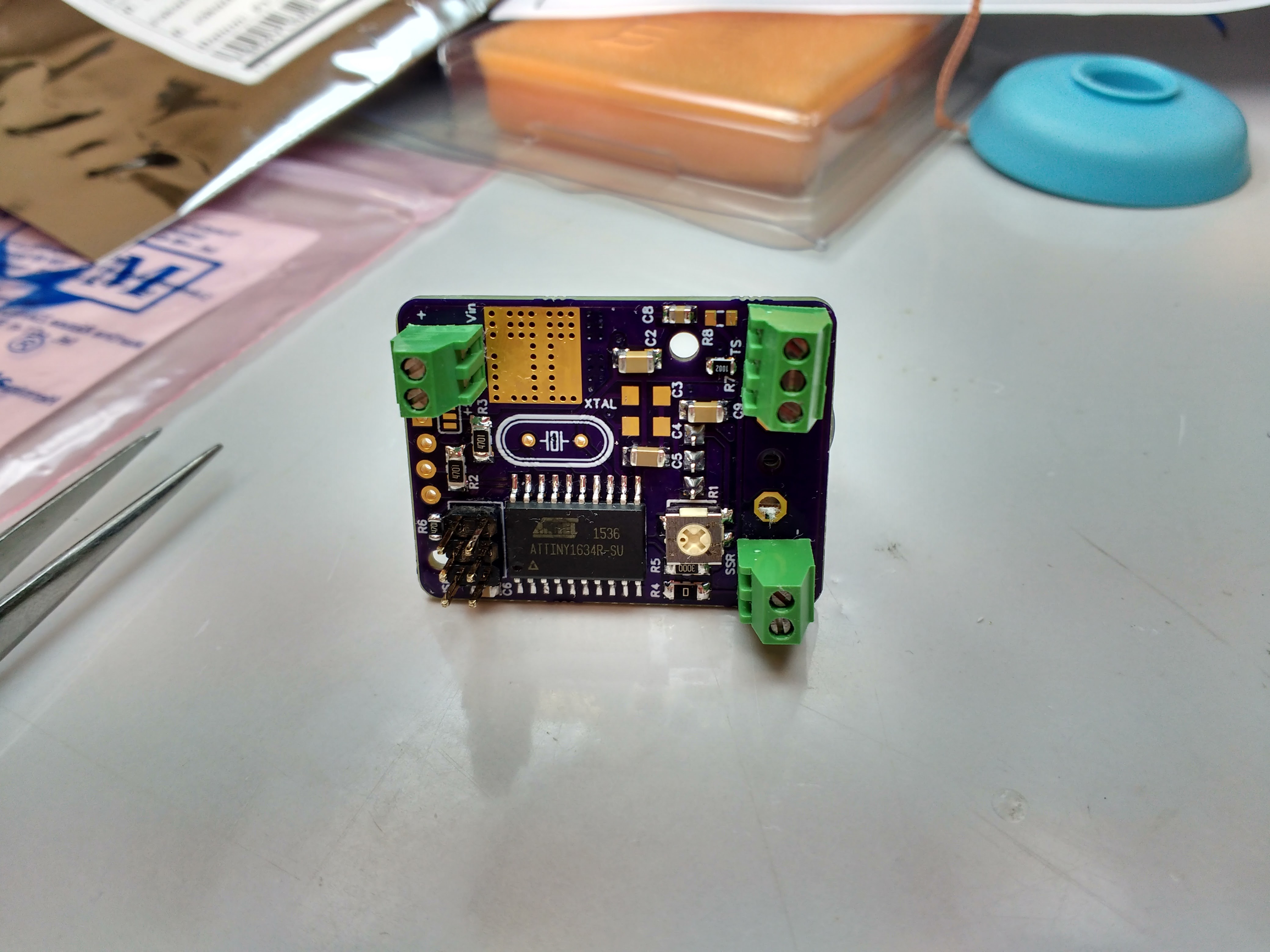
- ATTiny1634 - mainly because of 16 kB flash and price
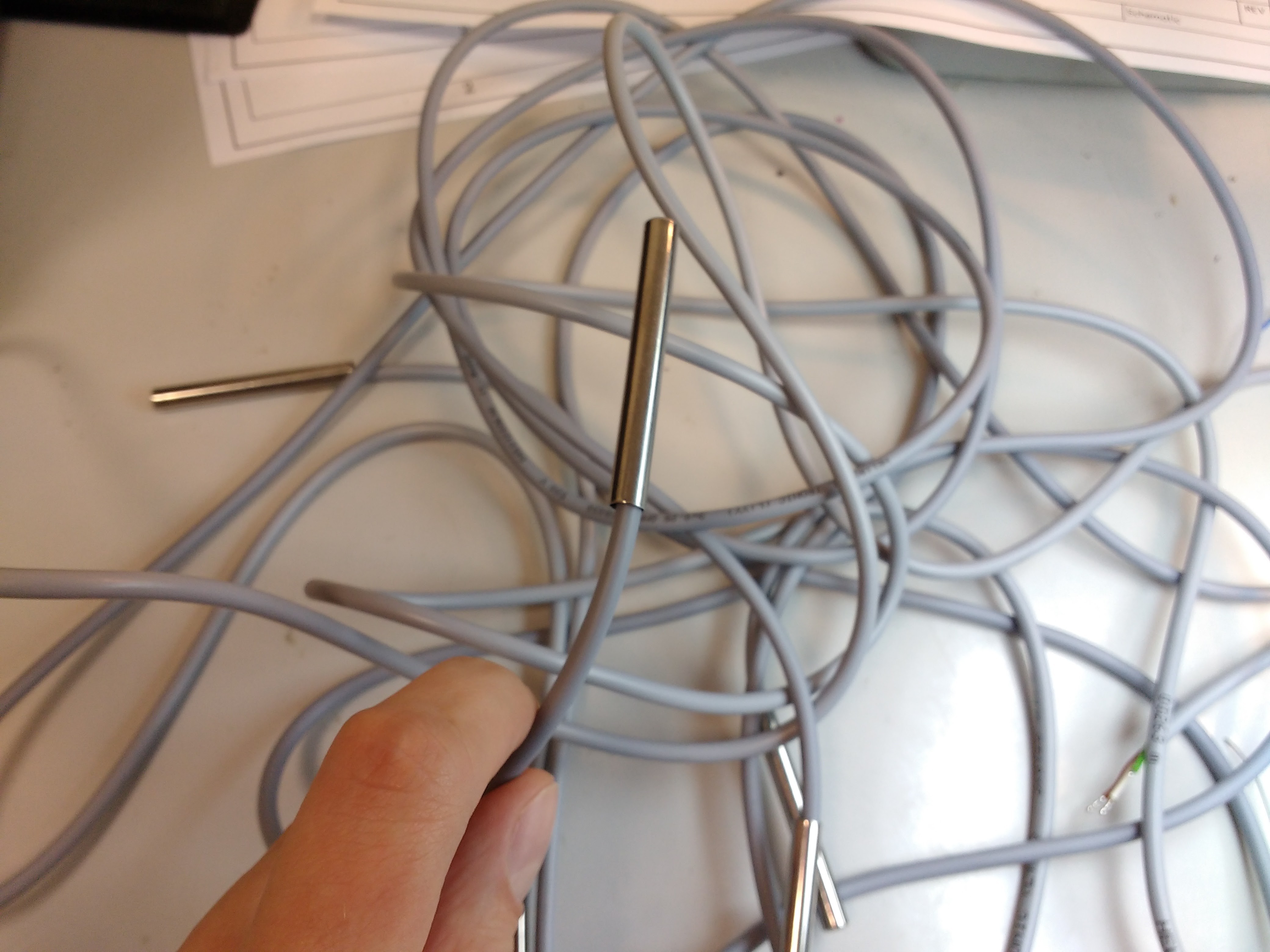
- LM35DZ temperature sensor
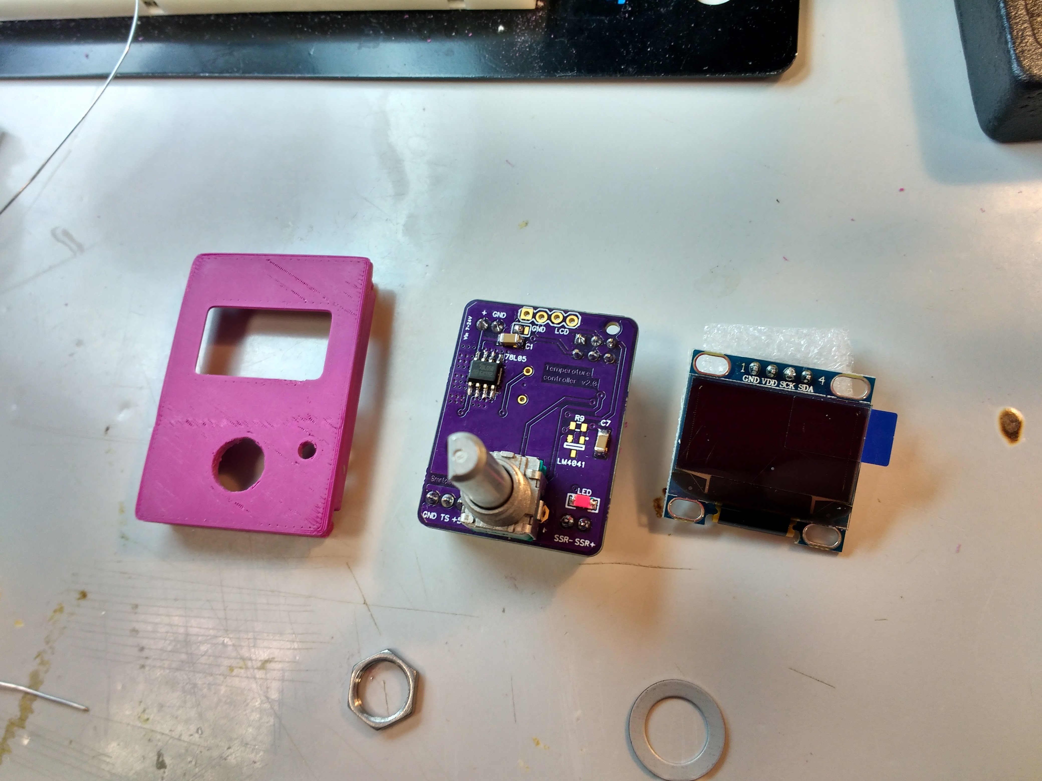
- 128x64 px SSD1306 OLED display
- 600 W heater in ca 100 l water tank
- SSR to drive and control the heater
Control
Everything is based on the PID algorithm with little tweak to avoid overshoot for different required temperatures (for different step sizes). This means that the classic control loop is used. Temperature is measured by LM35DZ sensor that gives 10 mV/°C.
To control heater power the duty cycle control is used. That means the heater is switched ON and OFF for certain amount of time from a fixed period. The result is possibility to set heater power from 0-100%. This can be achieved because of the high thermal capacity of water. (the process is "slow")
Control algorithm was simulated in Matlab/Simulink. It is all about Integration gain changing for different step sizes (step from actual to needed value).
To design PI(D) control I had to do 3 things:
- Measure and identify the system
- simulate the system in Matlab/Simulink and find the right setting for the controller
- write some code to transfer it to the ATTiny
1. Identification
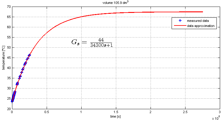
System identification was done using the heater at full power and measuring the response of the system (temperature rise). Measured data were approximated using 1st order lag function.
2. Simulation
There is a basic control loop on the next picture with some blocks added to make the model behave more like a real system.
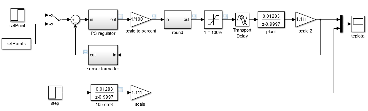
The idea behind the control algorithm i have used is to use PI control with a little tweak. If you want to use the PI control you need to tune the constants (P, I, D) of the regulator. The problem is one setting is good only for one situation (step size). So I change the setting of the regulator according to a situation (step size). I believe it is called gain shifting.
todo rest...
3. SW and control algorithm
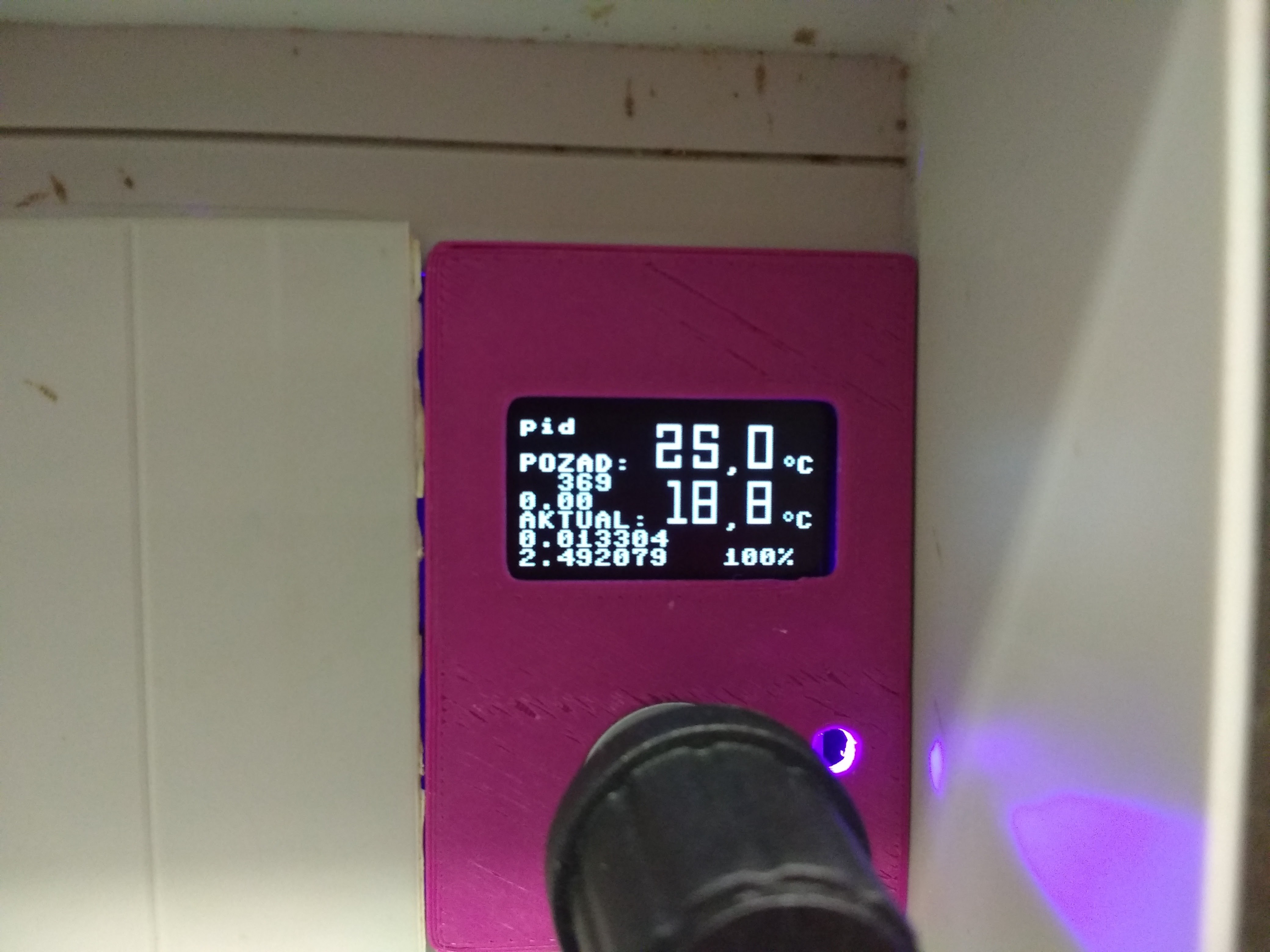
control algorithm looks like this
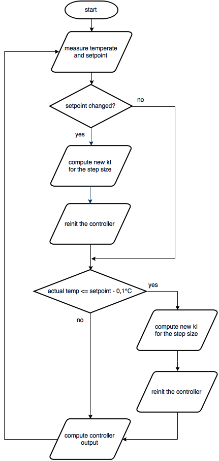
The main loop lasts 10 s. Each 10 s the setpoint and the temperature is measured and the controller output is calculated. If there is a setpoint change the algorithm computes new Ki constant and re-inits the controller. If the actual temperature is 0.1 °C below the setpoint It calculates new Ki constant because it makes the controller bit more "aggresive" and it can react to overshoot better.
todo...
TODO and problems
- PT100/PT1000 interface maybe?
- different settings for different heaters and/or water volumes
- Adding LM4040 2.5 V reference and opamp on mcu input to scale the sensor output and increase the accuracy.
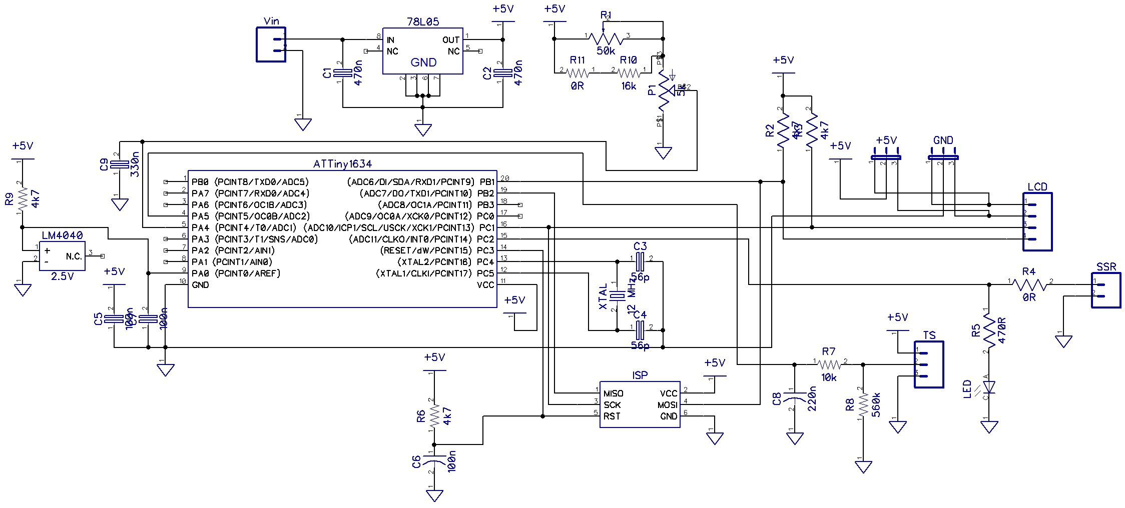
Schematic
Software
I have used Arduino core from SpenceKonde
SoftI2CMaster library
Arduino PID library
Arduino Timer library
todo rest....
 Kyle Gabriel
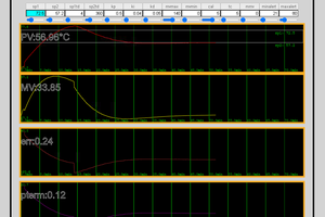
 justin.richards
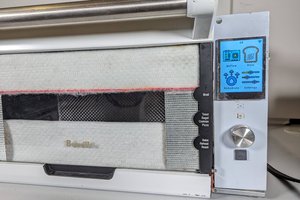
 Gonzho
DS18B20 sensors come in a waterproof design. A NodeMCU controller can host a free web page for monitoring and control instead of hardware. It can send the date to a cloud spreadsheet if you want. https://hackaday.io/project/171474-wifi-waterbed-temperature-control