 danjovic
The SILSpark is basically a Digispark Clone designed for DIYers as it features:
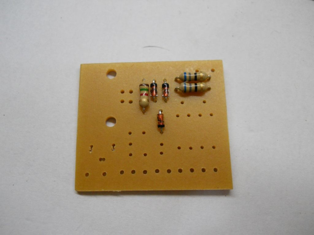
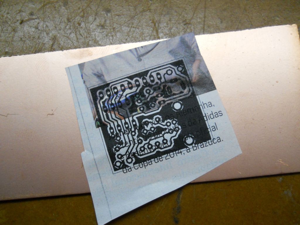
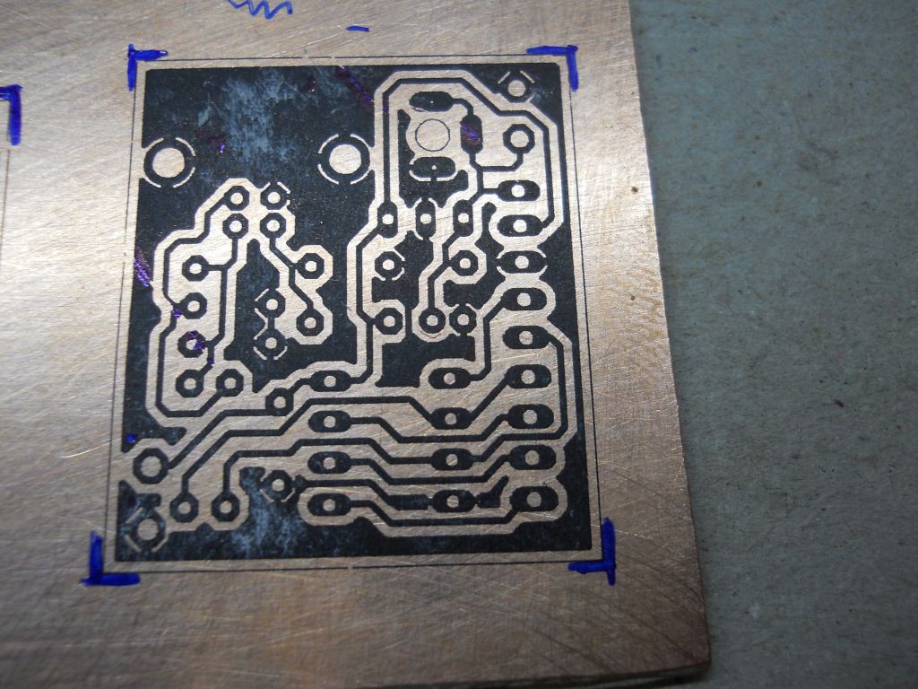
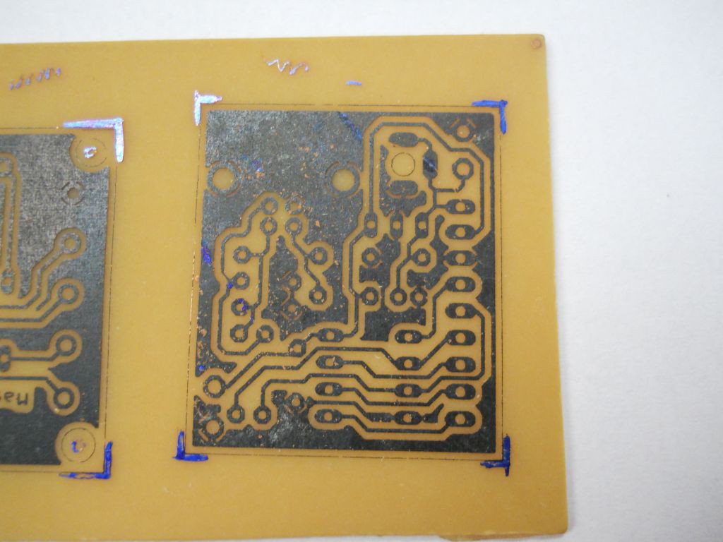
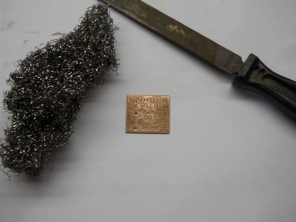
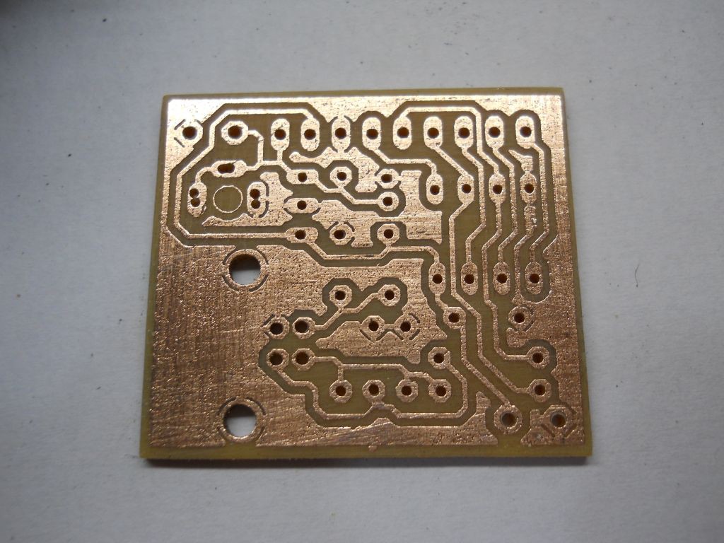
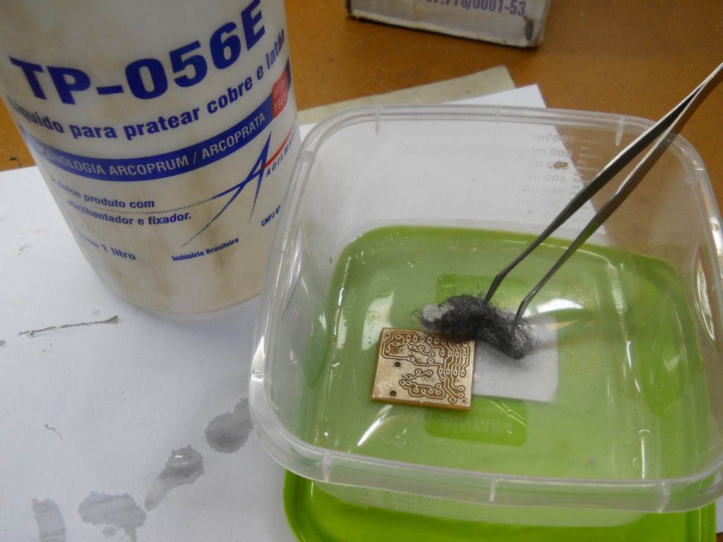
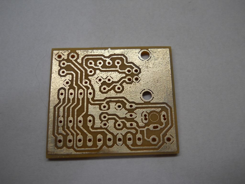
- Single Sided design, making it easy to reproduce at home using tone transfer or another method.
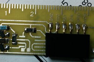
- Through Hole components, making it easy to assemble and to get components
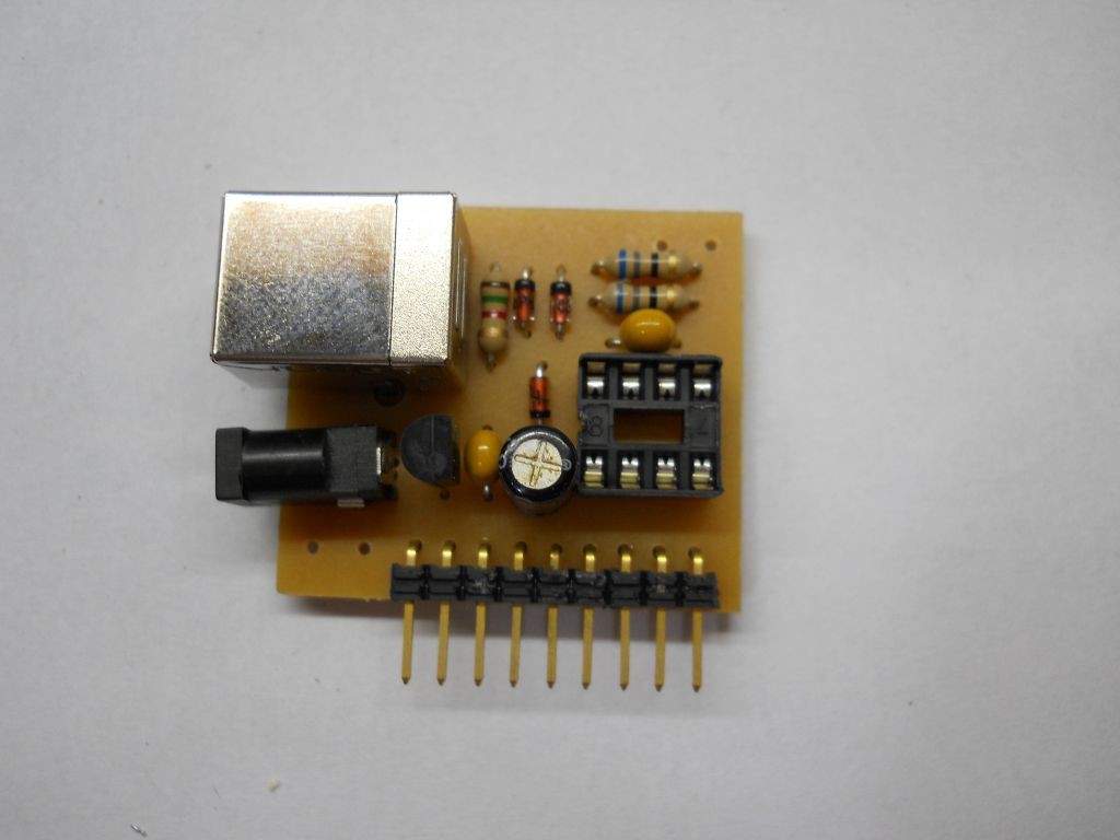
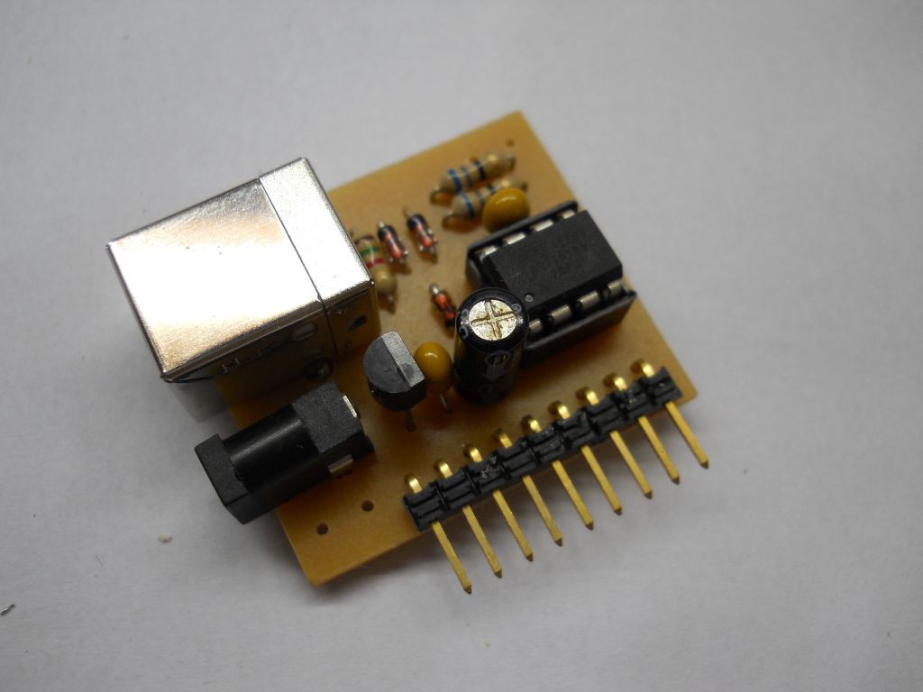
- Socket mounted DIL8 Attiny85 for easy replacement or reprogramming the bootloader specially when Reset PIN is used as IO.
- Several powering options:
- Barrel DC connector
- Pads for external battery
- USB connector
- Pads for +5V
- I/O connector
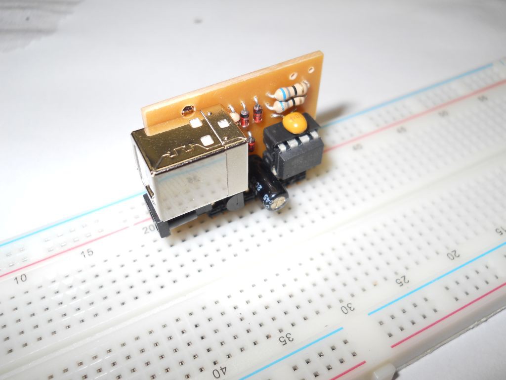
- SIL connector with all I/O pins as well as the power pins, making it easy to be mounted on a proto-board as well as making easy to attach 'shield' boards.

 XDjackieXD
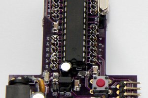
 Andrew Retallack
 technolomaniac