 Alvaro Ferrán Cifuentes
All the info on this project is available in github, including the board design, arduino library, servo firmware and mechanical parts as well as use instructions.
By enhancing the servo's capabilities, many useful new tricks are possible, from regular servo use
to controlling one servo by moving another one
or detecting a collision by measuring its current consumption.
All of the above examples' codes are available in the repo, as well as other, more complete examples.
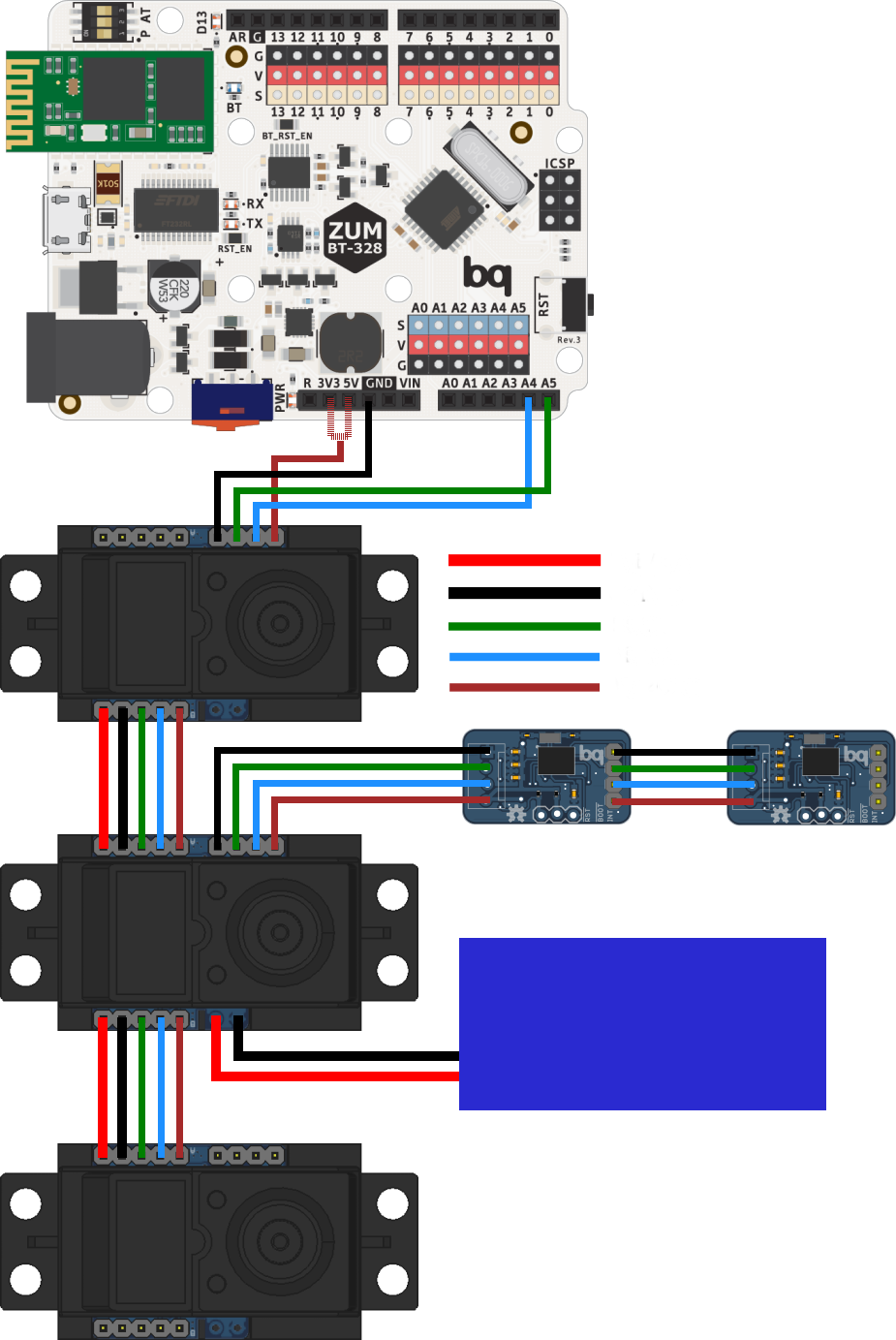
The servo has different connector groups:
- Main bus (5 lines): It is used to power and control the servos in daisy-chain configuration, attaching each one's A side to the previous' B side.
- Auxiliary bus (4 lines): Its function is to provide an extra link to the I2C bus, to allow other devices to be used at the same time.
- Power bus (2 lines): The main bus can be powered from the power bus on any servo, or from the last servo's main bus V_BAT and GND.
- Micro USB: Used both to upload the firmware to the board as to use it to control the servo directly from the PC, without involving other microcontrollers.


 patchartrand
 Luke J. Barker
 Boris Landoni
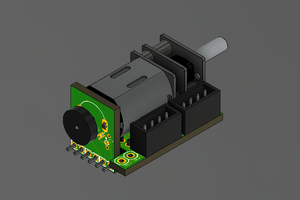
 Holotype Robotics
Hola Álvaro, ¿Qué tal?
I'm doing a similar project to IntelliServo. It's been many years since you did this project, but maybe you could take a look at it and give me some advice. :)
LibreServo | Hackaday.io
Cualquier consejo será bienvenido.