Musti
MustiCNC machine is usually controlled via parallel bus, containing six signals. For each of the three axes there are two signals: STEP and DIR. At each positive edge of the STEP signal, the corresponding stepper motor moves into direction set by DIR signal. In addition to these six signals, there can also be other general purpose control signals.
Parallel bus on longer distances and in noisy environment can be susceptible to electromagnetic interferences. Because of this we decided to design an interface to transport these parallel signals via an optical link. For successful transfer via optical fiber the first thing that must be done is to convert parallel data to serial bit stream. Moreover, because of the inherent design of optical transmitters and receivers, serial data must also be Manchester encoded.
Our design is based on Serializer / Deserializer for Audio Fiber Optic project published on Open Cores.
Use cases
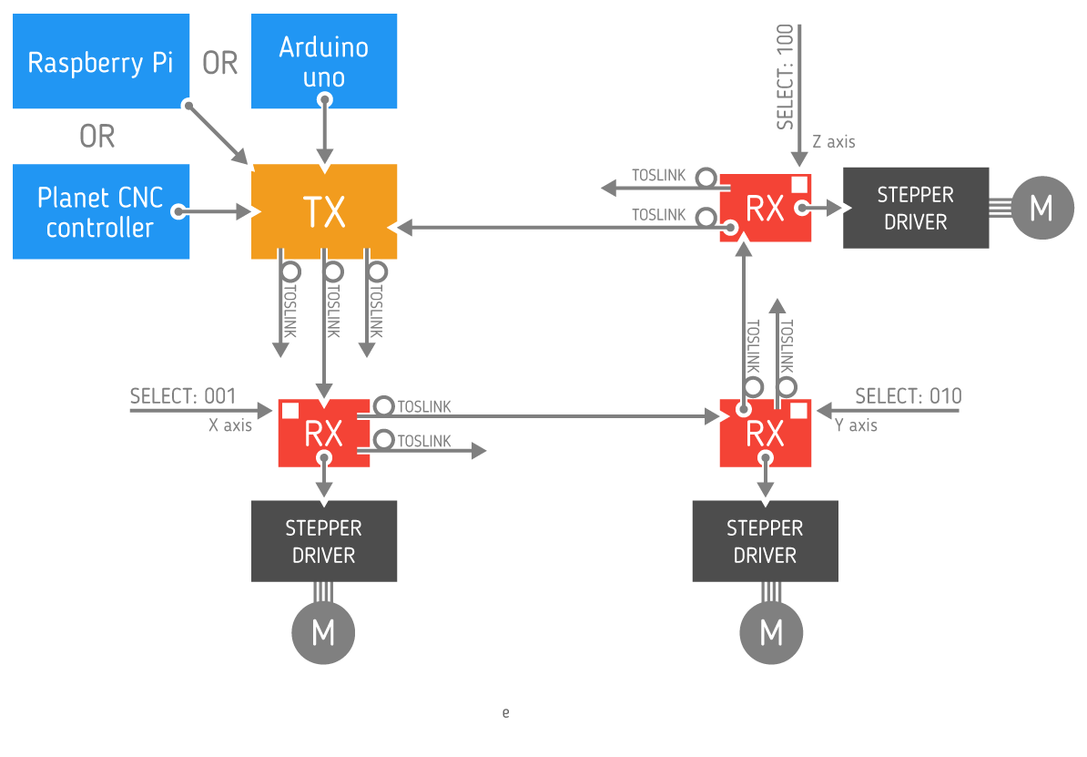
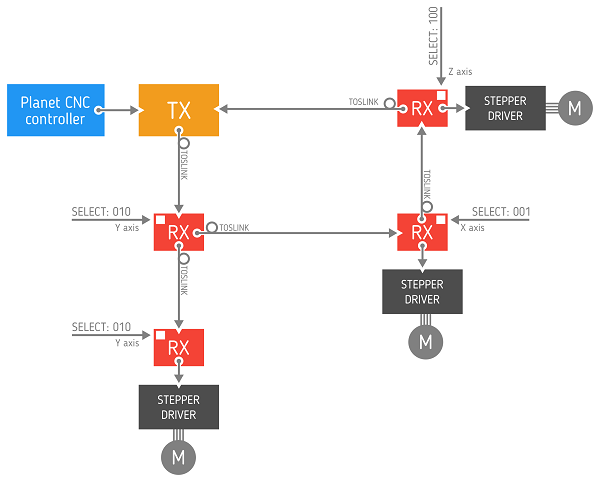
ToslinkCNC has been developed for use with GoodenoughCNC Plasma cutter as our answer to continuous problems with electrical noise and interference. The following configuration is used in the system.
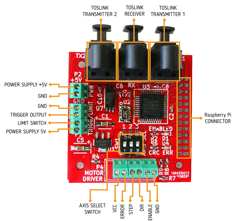
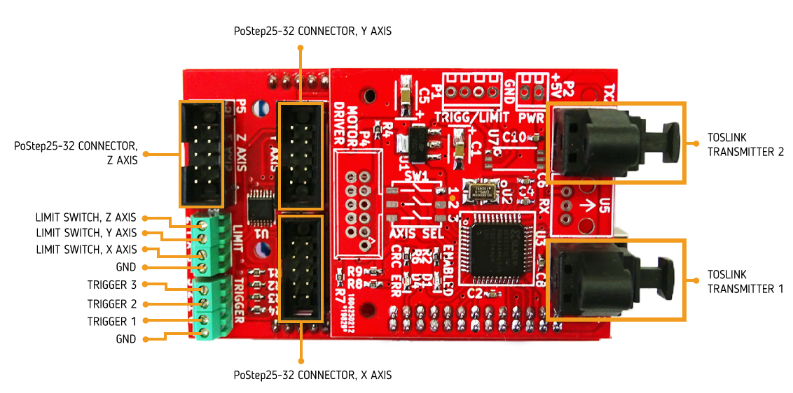
Toslink Receiver-transceiver
For each motor on the CNC machine there is one PCB, containing Toslink receiver. Receiver PCB, together with motor driver, can be mounted on the motor. Receiver is being used with PoLabs' PoStep25-32 stepper motor driver. PCB is being powered through motor driver connector using +5V. To enable this the +5V supply from motor driver should be connected to unused 9th pin on the driver's IDC connector usign a piece of insulated wire. PCB consists of one CPLD, two optical transmitters, one optical receiver, one DIP switch for selecting the axis and one limit switch / trigger connector. Limit switch is insulated through an optocoupler and trigger output is open drain type. Toslink transmitter DLT1111 and Toslink receiver DLR1111 were used, which enable data transfer speed up to 16 Mbps. We used Xilinx XC9572XL CPLD to implement the necessary logic for protocol conversion. Receivers can also be connected in daisy chain.
Using IDC-10 connector: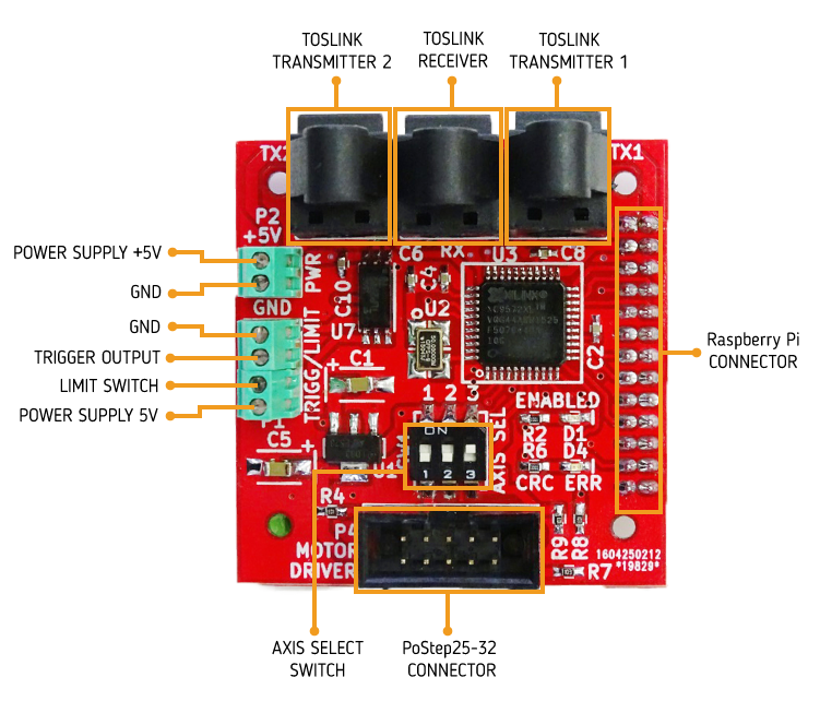
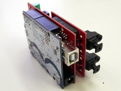
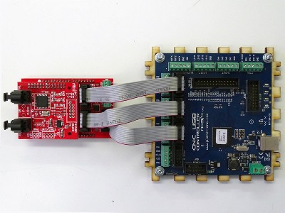
Toslink Transmitter
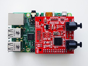
Transmitter consists of two PCBs, an Arduino sield and a Toslink transciever. Both PCBs are stacked together. Toslink transciever PCB is identical to one used for receiver. Arduino shield consists of headers for Arduino and connectors for CNC USB Controller Mk3/4 from Planet CNC and PoStep25-32 driver. There is also a terminal block for connecting limit switches and trigger signals. Circuit can be powered either through terminal block (+5V), through Arduino Uno if attached as a shield, or from Planet CNC Controller.
Toslink Transmitter - Arduino Shield
Toslink Transmitter - Planet CNC
Toslink Transmitter - Raspberry Pi Shield
Firmware Description
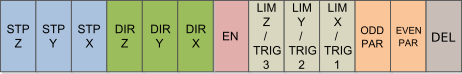
All data is being transmitted in frames of fixed length. Frames are transmitted without gaps between them. Each frame contains 3 direction values, 3 step values, vaule of enable signal, 3 values of limit/end switch signals (these fields are being shared with 3 trigger values), parity bits and frame delimiter. To detect parity bit corruption, both even and odd parity bits are being transmitted. Transmitter places direction, step, enable and trigger values in new frame, adds calculated parity bits and sends the frame to the first receiver in daisy chain. Receiver reads the enable value and direction, step and trigger values ( based on axis selection). Receiver replaces the correspondig trigger value with limit switch value, calculates new parity bits and sends this new frame to the next receiver in dasy chain. Output of the last receiver in dasy chain is connected to transmitter input. Transmitter reads all three limit switch values from received frame.
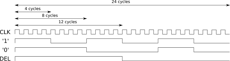
Data in optical fiber is manchester encoded. For logic '0', logic '1' and frame delimiter three different patterns are being used. They were selected so that all of them have the same length and are completely different from each other. Decoding is based on time elapsed between two rising edges of clock. If elapsed time is shorter than 12 clock cycles, receiver decodes it as a short step. If it's longer than 12 and shorter than 20 clock cycles, then it's decoded as a medium step. If elapsed time is longer than 20 clock cycles, it's decoded as a long step.
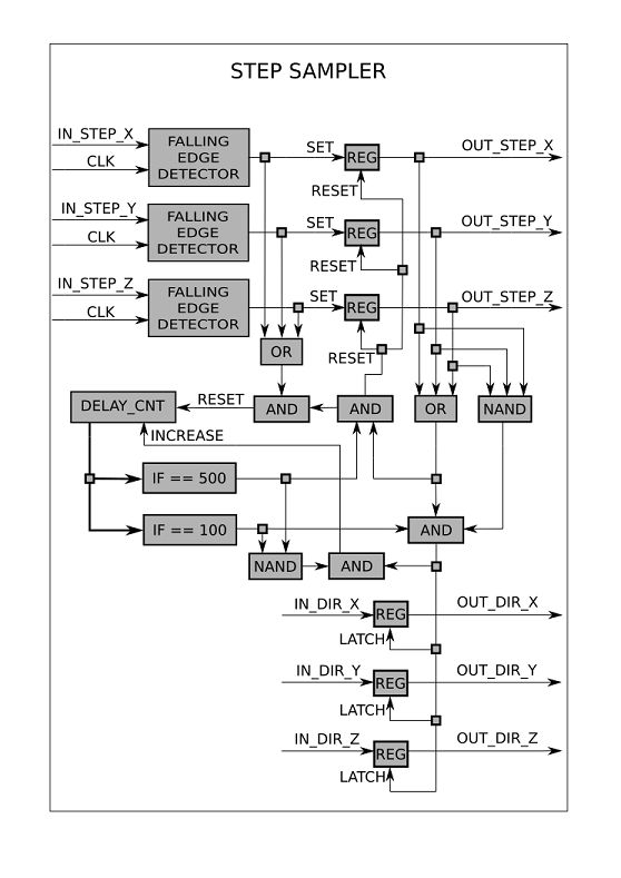
Main transmitter module consists of a step sampler and an optical transmitter. Step sampler samples and shapes incomming step, direction, enable and trigger signals and passes them forward to the optical transmitter. Optical transmitter handles data framing, manchester encoding and sends encoded data to Toslink transmitter.
Block diagram of step sampler is presented in figure below:
Optical transmitter consists of shift register and manchester encoder. Shift register block diagram is presented in figure below:
Manchester encoder consists of three look-up tables and one multiplexer. If value of tx_output is "00" the '0' pattern, if "01" the '1' pattern and if "10" the DEL pattern is generated on the output.
Main receiver module consists of an optical receiver and a step generator. Optical receiver accepts signal from Toslink receiver, decodes it and passes extracted data to step generator. It also adds limit signal values, calculates new parity, manchester encodes data and passes it foward to both Tolsink transmitters. Step generator correctly shapes the received signals.
Optical receiver consists of manchester decoder, shift register and manchester encoder (which is identical to the one used in transmitter). Block diagram of receiver shift register is presented in figure below:
Manchester decoder consists of a simple low-pass filter and a step sampler.
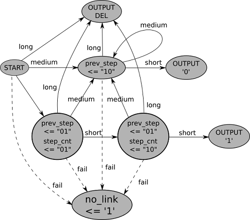
 Step sampler is a finite state machine. It's diagram of possible states is presented in figure below. Movement between states is based on received step width: short, medium or long. If step width is too long, the connection is lost and motor driver is disabled (enable signal equals to '1'). As soon as the correct manchester symbol is received, the connection is again established.