Sounds like a great hack!
Inspired by @ajlitt's #RPi WiFi (and I refer you there for instructions on building the kernel module etc), this project grew from a hasty implementation of the basics required by mounting an SD card slot on the back of a Pi Zero, with an ESP-03 mounted on a micro-SD adapter card:
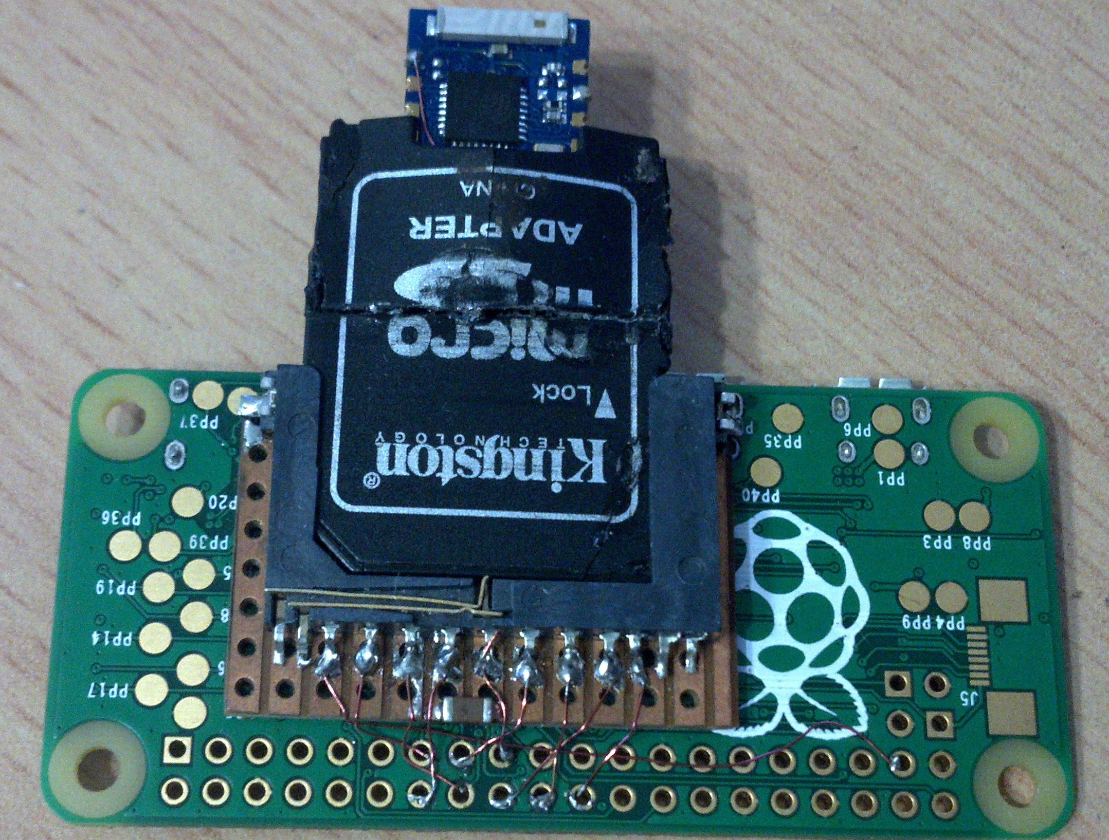 This worked well, and I found having the option to remove the WiFi & insert memory card handy.
Re-inserting the WiFi would cause the Pi to freeze, and I soon found that executing
sudo modprobe -r esp8089
prior to re-insertion would allow the module to reload & WiFi come back up.
To have this done automatically, a udev rule was created in /etc/udev/rules.d/60-esp8089.rules to unload the kernel module on removal of the WiFi card:
ACTION=="remove", KERNEL=="wlan0", RUN+="/sbin/modprobe -r esp8089"That was fine, but one issue remained - after issuing a "sudo reboot", the esp8089 WiFi would not come back up. I realised this was because the module still had the firmware on-board, uploaded by the previous linux kernel module's two-stage initialisation. I could see no way round this, bar simulating what I was doing in practice, namely briefly pulling the card out & re-inserting it.
Pi, tell me you're booting.
This need set the ball rolling on adding components to power-cycle the socket at every reboot. But how to detect that the Pi is rebooting? Was there a signal, with luck on the 40-pin header, which would show that the Pi was commencing the boot process?
It dawned on me that I could (mis-)use the HAT eeprom polling, done once only by the videocore VPU, before linux is even started. I connected my logic analyser and saw a low-going pulse train of ~3.5ms on both ID_SC & ID_SD, even when there was no HAT connected, and before the rainbow splash screen was drawn. Bingo!
I bread-boarded a simple pulse-stretching design based on an RC delay, and found that 330nF & 1M, with a couple of FETs to get a nice square pulse of ~300ms with the correct logic level, proved to work well.

My next challenge was to add an ESP-12E/F module alongside the SD slot, and see if they could co-exist somehow...
Multiple cards on the SDIO bus?
I was encouraged on reading this thread that I could simply parallel up a second device & have it work, the last post in that thread claims up to 40 cards on the MMC bus! Yeah, this is SDIO, not MMC, but worth a shot.
Alas no, one memory card or the other would work, whichever was inserted first, but at least the second card didn't interfere with operation of the first. While searching ebay for old SDIO peripherals I might try in the card slot, I noticed the TXS02612 SDIO port expander, pretty much a six-pole double throw switch for the signals. That there even was such a thing ended my hopes for two devices working at the same time on the SDIO bus.
As an aside, ebay also threw up this interesting card, a combo WIFi & micro-SD device. Pretty much what I was striving for, but not an option at that price, or as much fun, compared with the esp8266 hack.
So, back to my stacked SD sockets & the two memory cards. I snipped the Vdd wire to the working card, and smiled broadly when the other card popped up on the Linux desktop. It later turned out I should have investigated this more thoroughly, but that was enough for me to start putting a design together. The plan was simple - use the card-detect switch on the socket to turn off the esp8266 power in the same way as I'm employing ID_SD.
Learning KiCad.
What a pleasure that turned out to be - I could get hooked on this. With the aid of a few youtube tutorials I was soon up & running. I implemented jumpers here & jumpers there for socket only, esp & socket, 1-bit & 4-bit operation etc That was at a time before @ajlitt had vastly simplified things by noticing that the module's spi flash could be relied upon to sit dormant...
Read more »

 Zepan
Zepan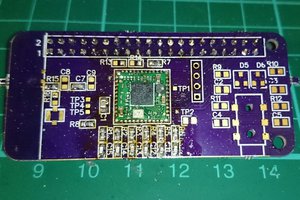
 jacksonliam
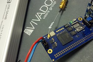
 Antti Lukats
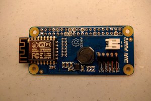
 ajlitt
Do you maybe have a schematic of how you hooked up the SD card to the RPi ?