 Jarrod
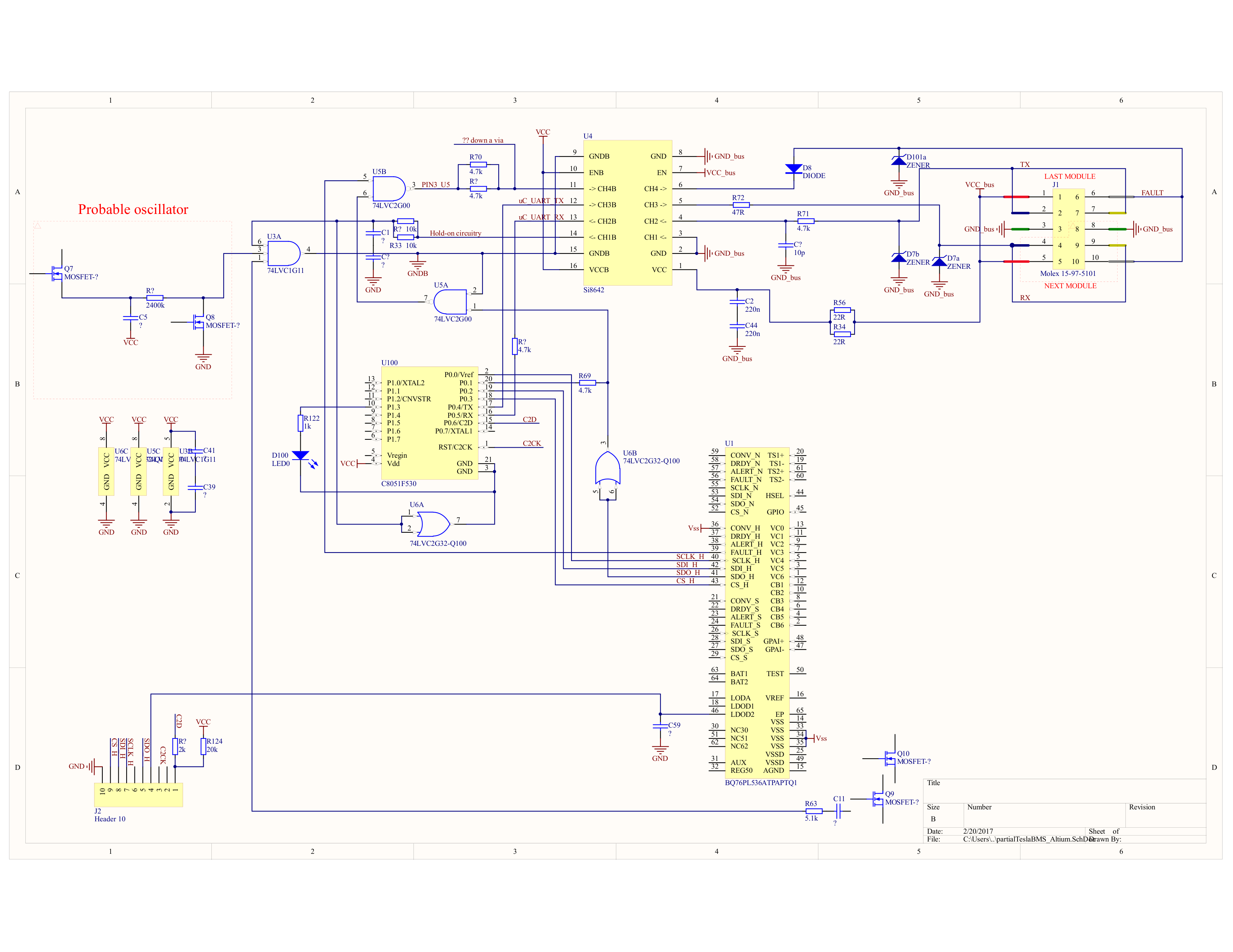
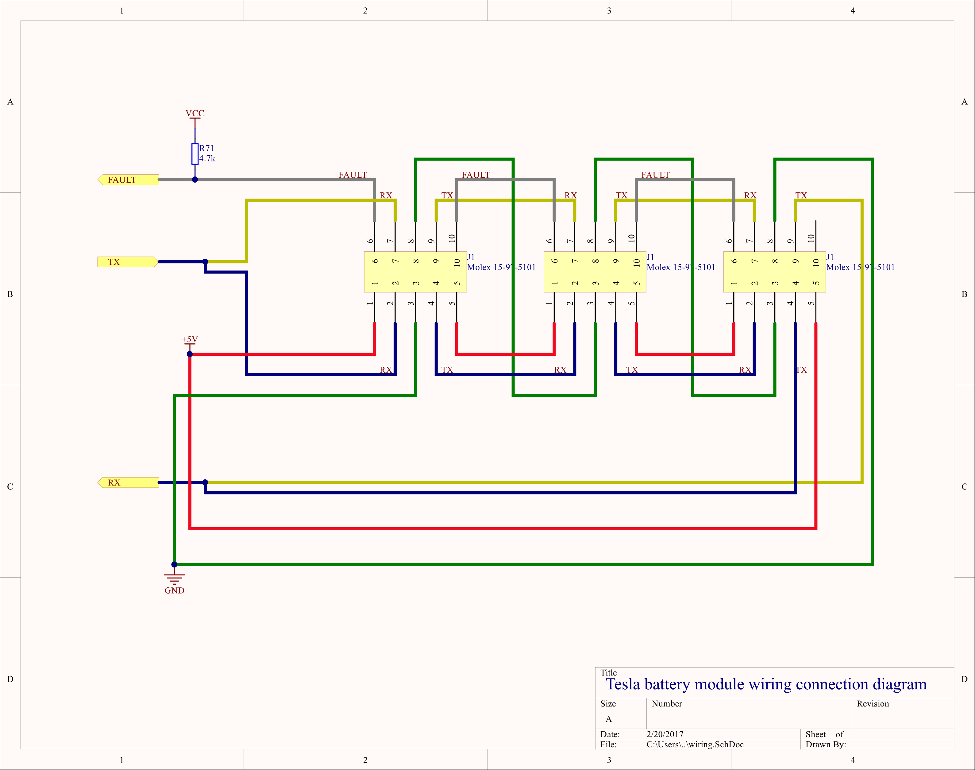
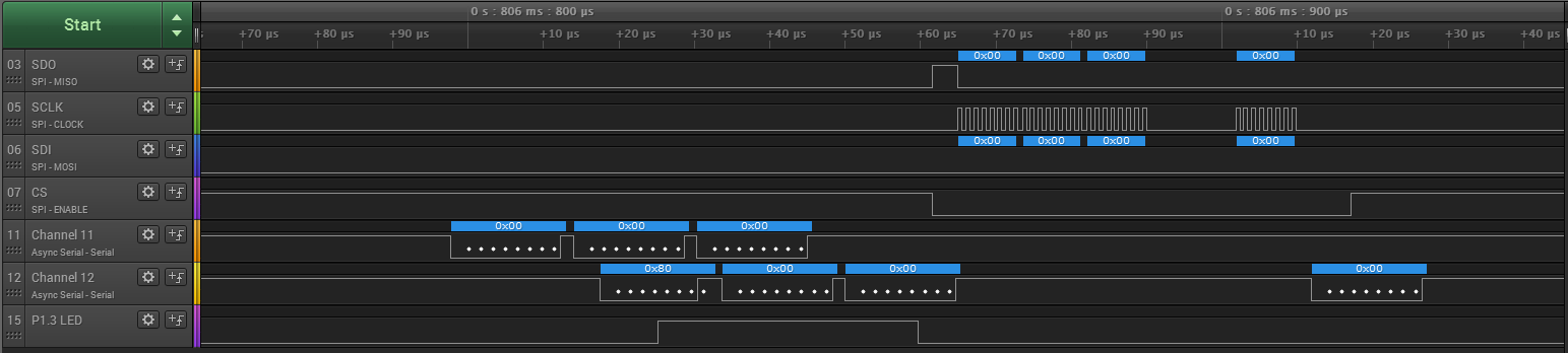
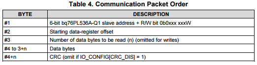
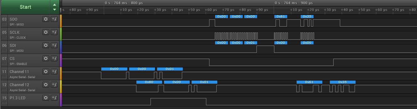
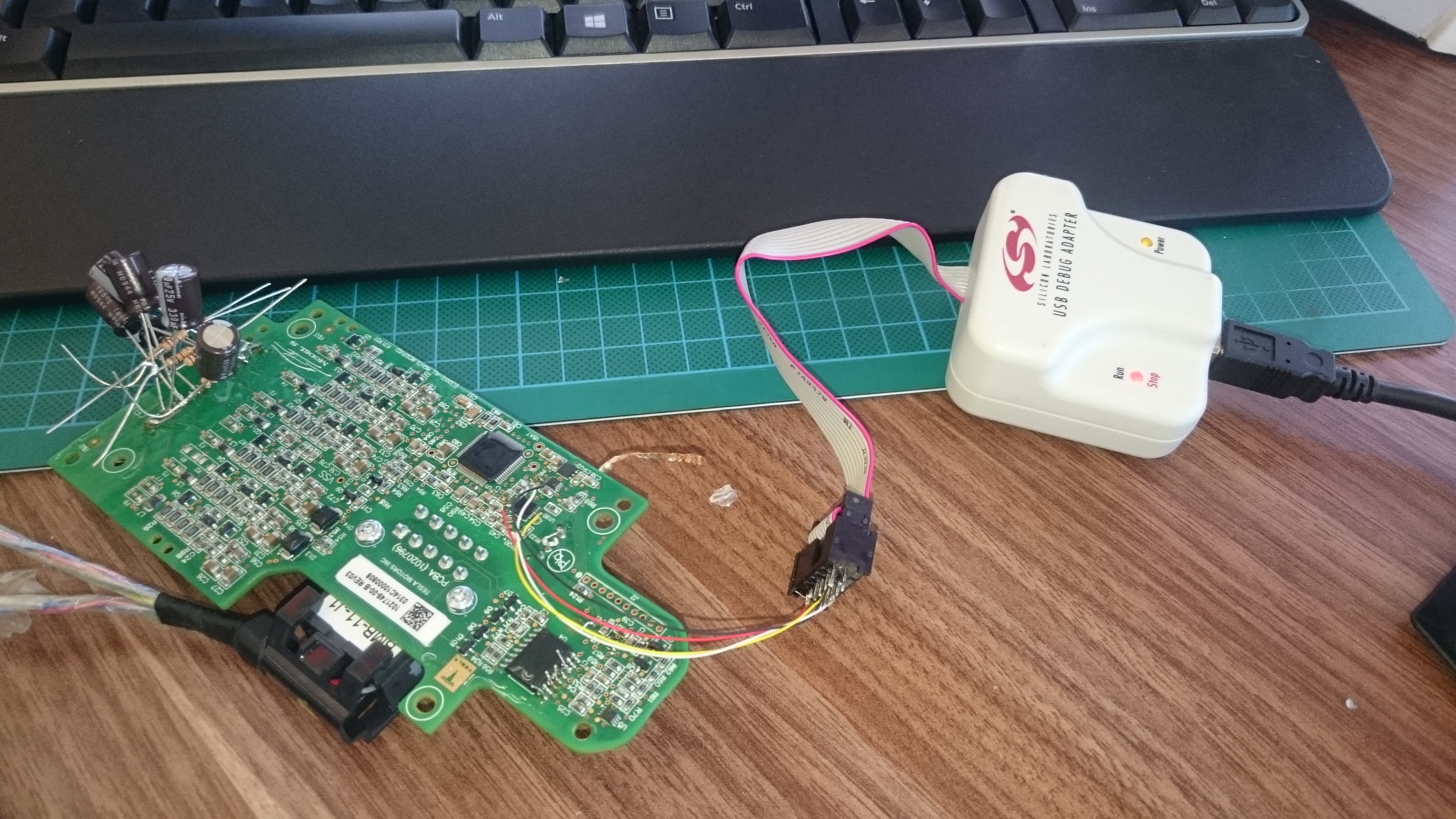
We now know the basic communication scheme used within the pack between each of the 16 modules! check out the project logs.
A basic Arduino Due based BMS controller is up on Collin's Github: (The BMS available from EVTV is based on this project.)
https://github.com/collin80/TeslaBMS
Another branch for the Teensy 3.2 by TomDeBree: (this one includes hardware design)
https://github.com/tomdebree/TeslaBMS
We are currently working on code required to preform basic cell voltage and temperature measurements, and implement a cell balancing scheme.
Other features will include:
- A charge controller to interface with an OEM charger via CAN bus.
- DC Contactor control circuitry including pre-charge capability.
- Current shunt for tracking state of charge (fuel gauge) and providing over current protection.


 surfingsteve
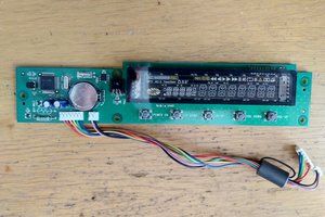
 Lauri Pirttiaho
 Hari Wiguna
 Hacker404
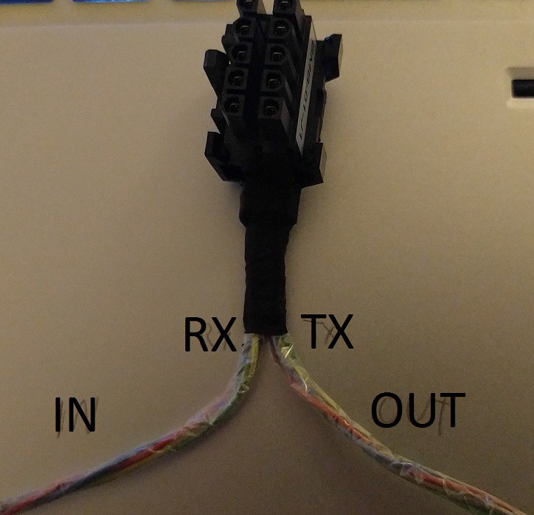
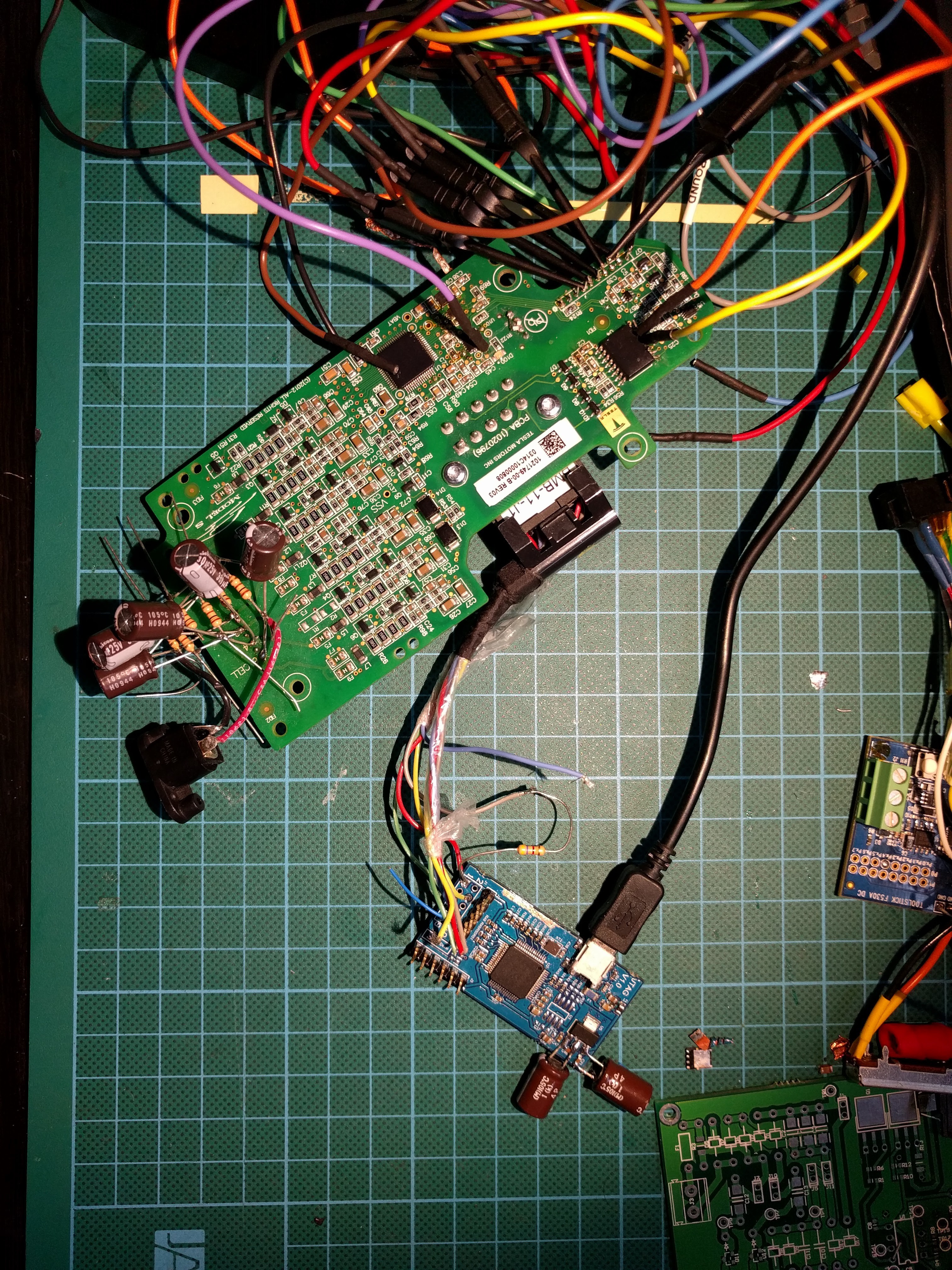
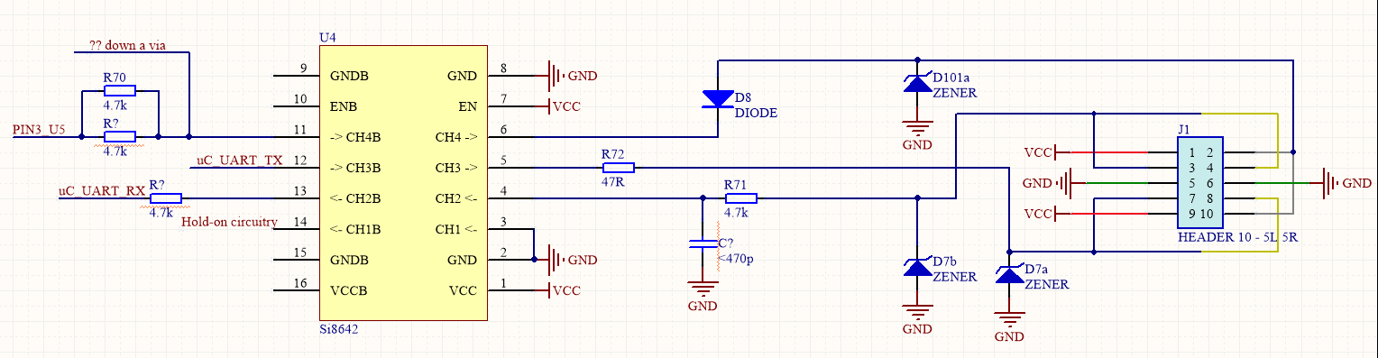
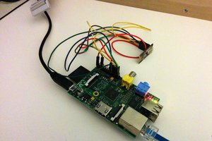
FWIW, due to the digital isolator chip on the slave BMS boards, you can power them with 3.3V and use a 3.3V serial port. I hooked up a Raspberry Pi to the slave board connector directly (no voltage dividers etc) and am communicating.
Thanks for your work. I'm converting a motorboat from 1920 from diesel engine to electric, using Tesla modules: http://electric-boat.lewin.nu/