 Eric Hertz
Oh man...
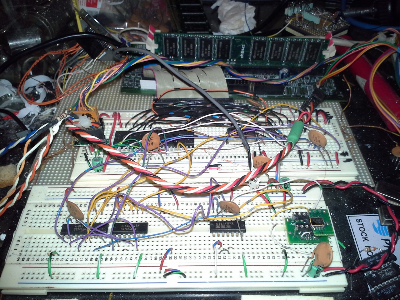
For a bit of background, the ol' #sdramThing4.5 "Logic Analyzer" peaked at 30MHz, Admittedly, its wiring was a bit of a "rats-nest," due to the progression of prototyping... but it was on a soldered breadboard. And, yahknow, I did my best to route those wires in reasonable ways that wouldn't be too long, dramatically differing in length, or too close to other signals which would cause crosstalk, etc.
OK.
Well, now... This might be a "duh" to the most've'ya'all, (if you were raised in the '80's anyhow? Is "duh" still a term?). But I replaced the 74LS00 on this project with a 74HC00... and... now it runs up to 30MHz!
OK!
On a *solderless* breadboard, no less... And, yahknow, these guys are known for their wonky-factors such as "huge" capacitance between pins, etc. Nevermind, again, a ratsnest of wires... (I certainly don't have the patience to cut those wires so they're proper-lengths to lay flat). And, yahknow, the weird layout of the power-signals... (power's coming in via the multi-colored twisted-cable near the uC, which is the programming-header, and the entire circuit is powered *exclusively* by the surface-mount 3.3V regulator on my FT2232H-breakout-board!)
Nevermind, again, much like on sT4.5, the one-shot circuits, etc. are quite a bit further away from the SDRAM, introducing wire-delays in both directions in addition to the delays introduced by the glue-logic (though, I made a bit more effort to reduce the back-and-forth delay by inserting an additional latch at the outputs).
Yep, again, we're talking: I *was* using a 74LS (rated for a minimum of 4.5V) on a circuit running at 3.3V... And, it worked great for up to 22.3MHz. I didn't expect it to run within-specs, but I made-due with what I had... and was more than pleasantly-surprised. Until I found this 74HC00 in my collection. Bumping "up" to the 74HC consisted of nothing other than popping that old LS and replacing it with an HC... No wiring-changes.
ONE change: The One-Shot circuits are now driven through an *inverted* clock-signal (so they *ideally* latch on the *opposite* edge of the SDRAM, but, yahknow, HC's aren't really *that* fast, so it's likely the propagation-delays are shifting that a bit). I definitely experimented with inverting that clock-input in the old setup... So, the HC is definitely the factor in this speed-increase, and might just indicate that even faster families would run even faster on this breadboard setup. (Note that I've been using a *much* faster 74AHC574 as the D-latch in my one-shots from the start...)
For #sdramThing4.5 "Logic Analyzer", I used a 74S51 (S, not LS, yes, I tried *numerous* 5V families, which all worked, but definitely with different speed-limitations) as a multiplexer... due to supplies. I found the S to be faster than the LS, (and still functional) even at 3.6V. (That multiplexer is NYI on this project... And may not be, as this is not a Sample/Repeat logic-analyzer, but a Sample/Read-Back, which mightn't necessitate a MUX for the "Side-Kick"). And, 30MHz was the limit... The other chips were all HC, so ... Kinda makes me wonder if I'da invested in an HC++ for that 7451, if I coulda bumped that up even higher, despite the ratsnest.
And, of course, I have every intention of using higher-speed (3.3V-compatible) 7400-series chips in the future.
..........
So here's a moment where I might just add a slight tangent in the project-path--first, to take a moment to Thank the folks 'round here at Hackaday for selecting this project for a bit of funding! With a bit less of a budgetary-constraint, I might take a bit of a more "scientific-method" approach with this wonky prototype--invest in some higher-speed (DIP/Breadboardable) 74-series chips, and just see what this ol' breadboarding-technique is capable of, in addition to the original plan, of course, of designing a PCB and using surface-mount chips.
.......To be honest, I never expected this wonky-breadboarded-circuit to go this fast... Guess yah learn something new every day!
Here's some output from the system, as it's running, currently:
Boot
# colShift = 1
...Verified.
col 4096 <-- 12
@0 read: 12
col 2048 <-- 11
@0 read: 11
col 1024 <-- 10
@0 read: 10
col 512 <-- 9
@0 read: 9
col 256 <-- 8
@0 read: 9
# 9 col addr bits
= 512 col/page
row 4096 <-- 12
@0 read: 12
row 2048 <-- 11
@0 read: 11
row 1024 <-- 10
@0 read: 11
# 11 row addr bits
= 2048 rows
bank 2 <-- 1
@0 read: 1
bank 1 <-- 0
@0 read: 1
# 1 bank addr bits
= 2 banks
16777216 bytes = 16 MB
Loading FreeRunner Loop...
/...done
Starting FR: 2048 rows
29389
29159
29158
29164
29157
29156
29160
29157
29158
29159
29163
(SEVERAL hours later, and it's still free-running! This is lookin' pretty stable)
After boot, it detects the SDRAM chips' dimensions (number of Columns, Rows, and Banks)
(This DIMM is pretty small, imagine what a 256MB DIMM would do...)
Plans are in the works to provide for e.g. sampling 8-bits for 4x as long. That shouldn't be a huge change, but might involve a shift-register attached to the Side-Kick's DQM inputs. Since those DQMs already have to be registered, converting it to a (selectable) shift-register shouldn't be a huge deal.
So, we're seeing 29160 rows/sec * 512cols/page * 1page/bank * 2banks/row = 29.86million cols/sec, or, yahknow, 30MS/s with this 30MHz crystal oscillator. (I'm guessing the inaccuracy is due more to the fact of how I measure "one second" on the AVR "host" than any other factor, but there's also the possibility the Crystal Oscillator isn't 100% precise, and there are *two* involved...)
Oh, and ColShift... Well, that was a thing early-on... Now, I'd've expected it to be 0, as my timing-diagrams are pretty well-understood, at this point. But I've been cleaning up the code recently, and somewhere in there it went from 0 to 1... (I think I deleted a delay() somewhere I thought it was unimportant). ColShift is the difference in *requested* column-number from that used during a *write* vs. getting that same *requested* column back in a *read*. A little strange that it's still a concern at all, and, again, likely due either to the removal of that delay(), or due to a delay introduced by the clock's being inverted before feeding into the D-Latches.
Discussions
Become a Hackaday.io Member
Create an account to leave a comment. Already have an account? Log In.
Thread's getting deep...
@K.C. Lee Interesting rule-of-thumb... so if I understand/remember correctly, there's the one that says signal propagation is roughly 1ns / 6in of wire.
And what you're saying is that, e.g., say Trise/Tfall = 1ns, then 1ns/6 * 6in/1ns = 1in before needing to worry about termination? That's quite a bit shorter than I'd've thought, but was definitely thinking more along the lines of pulse-width rather than rise/fall.
Are you sure? yes | no
( FYI: since I've done a lot with AVRs, thought I'd see what they claim as Trise/fall... and it's slightly more complicated than looking in a data-sheet: http://www.avrfreaks.net/forum/rise-time-avr-gp-port-pins )
Thanks, all, for the heads-ups on transmission-line stuff... here and in that other log a while back. It has indeed been dang-near a decade since I studied/used that stuff... might be wise to dig out my ol' text-book when it comes time to PCBify this thing. But I've gotten some great rules-of-thumbs and keep-awares from y'all, Thanks!
Are you sure? yes | no
It is always the edges that is causing the issue. That ratio could be smaller/larger depending on how much overshoot/undershoot you are allowing. A short piece of wire means that the wavefront can make a few round trips during the rise/fall time. The reflections sees a fraction of the full swing so the amplitude will come out to be smaller.
http://www.ttelectronicsresistors.com/pdf/application_notes/HighSpeedDigital.pdf
They are using the 1/6 ratio in the app note.
Are you sure? yes | no
Interesting document, Thanks!
Are you sure? yes | no
They don't typically tell you the rise/fall time in a regular uC datasheet.
ATmega has a rise/fall time for SPI in section 29.6 table 29-18, row 3 for SCK Master: 3.6ns typ (i.e. not tested for production) That's likely the fastest I/O on that chip. (2-wire interface intentionally slowed down the fall time as a requirement, so it is not a good way to gauge the overall speed.)
The good vendors have IBIS models so that you can figure out the output impedance etc. and use for simulation.
Are you sure? yes | no
Indeed, that's basically exactly the conclusions at that forum-post I linked. Makes sense, the rise/fall times would definitely depend on the load.
Are you sure? yes | no
:cough: FPGAs can run at those speeds easily... and be changed at a moments notice with programming :cough: WHO SAID THAT! I know it wasn't me 'cause I promised not to....
Are you sure? yes | no
*cough*
Are you sure? yes | no
Wonder what the drive-strengths on that FPGA are ;)
Are you sure? yes | no
On the PSoC, they are pretty darn good, since it's routed out through standard IO pins on the uC.
Are you sure? yes | no
FPGA drive strength are programmable because they support multiple driver standards. (They select the number of drive transistors.) Also impedance control, slew control, termination options etc.
Are you sure? yes | no
Now you have me wondering if a 74AC00 will make it go even faster, or break things because of crazy edge rates and ground bounce and all the other goodies that come with the untamed speed of AC...
Are you sure? yes | no
Interesting proposition. I think I have a few sparse AC components in my collection, but judging by how rarely I've spotted 'em, odds are against their being the ones I need.
Had been pondering that, though... As I recall, HC components at 3.3V are actually *slower* (longer propagation-delays, at least) than LS at 5V... but maybe I'm mistaken. Regardless, it's likely there're several factors at-play here.
No problem visualizing that ringing/overshoot/ground-bounce of any sort, especially that caused by fast-edge-rates, could cause tremendous problems if fed into a clock-input... hmm. Although, again, the inverted-clock wasn't necessary with the LS at 22.3MHz... Also calls into question the clock-fan-out chip I'm using, which I would find pretty shocking if its output-edge-rate was a function of the frequency. Pretty sure I 'scoped that thing as pretty much a square-wave.
Hadn't been paying too close attention to edge-rates.
Are 74AC's known for these sortsa problems, or are you just using them as an example of high-speed devices?
We come into that gray area, as was mentioned by @James Newton in another comment-thread, e.g. RS-232 was specifically designed with shallow edge-rates in mind, and surely for a multitude of reasons not limited to merely the obvious, EMI, crosstalk, etc... nor limited to merely the facts of how it was often-used at the time (long stretches)... and, probably not even limited to the factors of the available technologies at the time... (seeing as how those specified edge-rates are *maximums*, not *minimums*) and, yet, we live in an era where nearly every serial port that claims compatibility with RS-232 completely disregards those specs. Kinda makes you wonder what's changed since then.
Are you sure? yes | no
AC seems to have a reputation for causing problems, and I think I read somewhere that a few of the latter CMOS families were an attempt to correct the issues introduced with AC. I like them for analog-ish uses like 50-ohm drivers and such because they have a nice +/-24mA drive (and they're very fast). Also because I picked up a bunch of surplus ones cheap :-)
That actually brings up another point - maybe the 74HC works better because it is better at sourcing current than 74LS. The bipolar TTL families sink current like nobody's business, but they are weak on the high side. 74HC drive is symmetrical, I'm pretty sure. Maybe that helps squash reflections and stuff.
Are you sure? yes | no
74HC has slow slew rate - so you can get by without termination for a long piece of wire, weak drives i.e. higher driver impedance - probably in the 100+ ohms range. Once you introduce a faster slew rate and stronger drive, then you have to start looking into terminations.
Rule of thumb is you can get away with 1/6 of length of rise/fall time * propagation rate (give or take) of unterminated line.
Are you sure? yes | no
Good call regarding sourcing vs. sinking current... I tend to forget about that... guess I've gotten spoiled with all these newfangled AVR-projects, and 20-40mA high/low outputs ;) Actually, differing drive-strengths is a really good point, considering just how many SDRAM chips are being fanned-out-to. (16!)
Surplus is nice :)
Found this about Ground-Bounce, and specifically the AC series... looks quite informative:
https://www.fairchildsemi.com/application-notes/AN/AN-640.pdf
(That'd've been a heck of a lot easier to find if Google still allowed wildcard searches!)
Are you sure? yes | no
Interesting you've gotten me on this 74AC realm... Apparently *still* amongst the highest-speed devices (stocked) in DIP packages. AHC seems to be a close runner-up, and LVC has *a few* in DIP packages... otherwise, it seems the fastest of the 7400's in DIPs are actually in the TTL (vs CMOS) realm, from *decades* ago. Weird.
But: The surface-mount devices... those seem to come in a *much* wider variety. I even saw some D-Latches rated for 500MHz(!). I've just invested in some (T)SSOP breakout boards for that purpose.
--------
And... I apparently used some AC245's as buffers for a text-based LCD-display on a project a while back, and was surprised to have had *any* issues with my addition of 245 buffers... But adding them actually made it *worse*. It actually worked more reliably *without* the buffers, despite my 3.3V microcontroller's outputs not being within the 5V-input specs of the display. Kinda boggled my mind at the time.. But, now that you got me thinking about this AC ground-bounce and whatnot, makes me wonder if that's where the problem was (especially, e.g., on the *strobe* input).
Are you sure? yes | no