 Eric Hertz
UPDATE2: Wow! 27 hours! I mean, yahknow, it'd be *easy* to bump a wire on this thing sitting right above my keyboard... but still running at 50MHz. Cool.
UPDATE: Been "Free-Running" continuously for over 5 hours straight at 50MS/s... I might go so far as to call it reliable! (and more notes added below regarding 62.5MS/s and the IDE-breakout... and completely rambling below.)
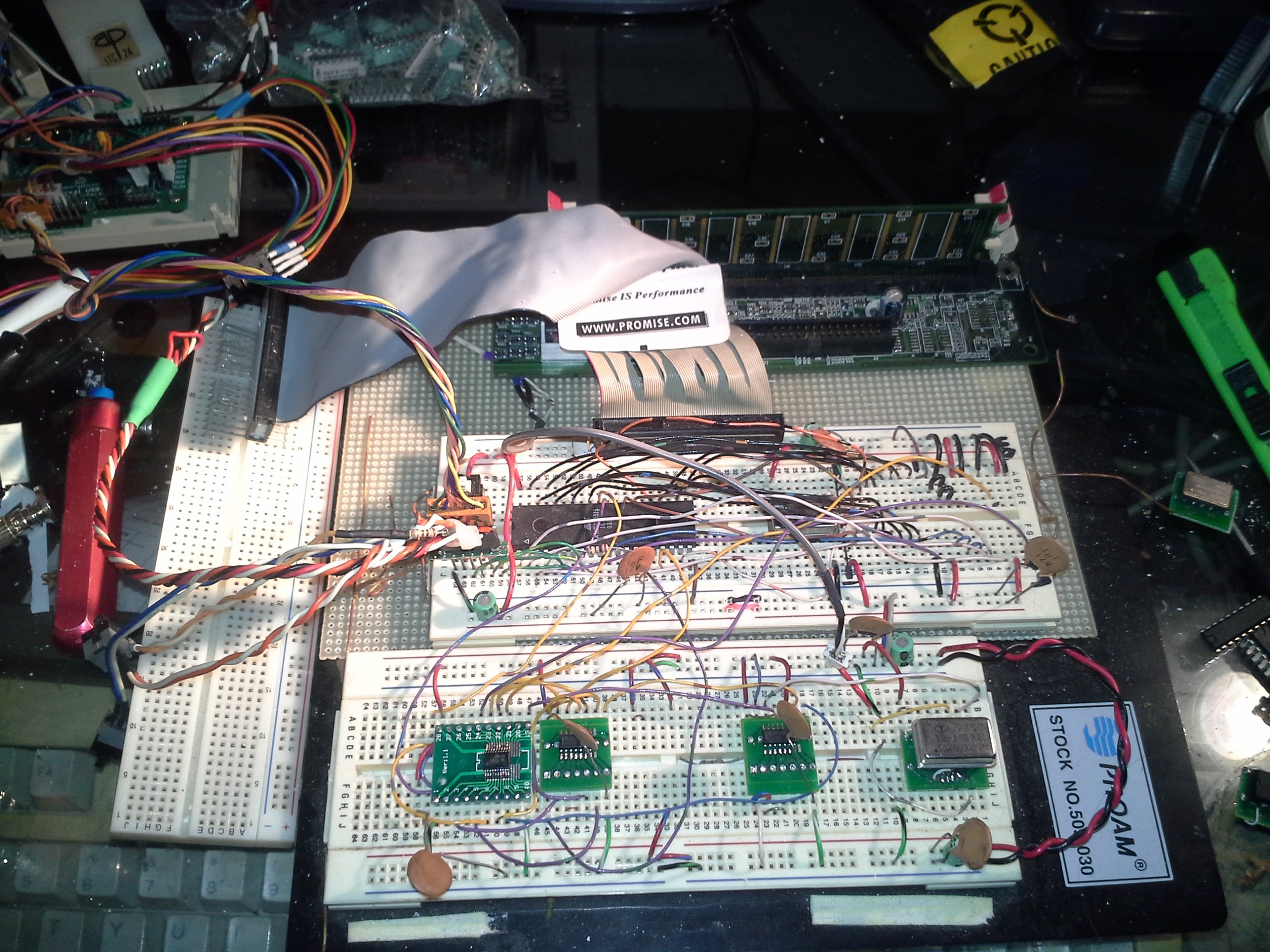
The short ribbon-cable is a "breakout" for the Free-Runner half of the DIMM's memory-chips, including the Address/Command signals. The longer ribbon-cable, leading to the left, is for the Side-Kick, which will handle the actual sampling of data to be [logic]-analyzed. Currently the Side-Kick/sampling/trigger-handler are not yet implemented.
A brief overview (explained in various previous logs): The system is currently controlled by an ATmega8515 (upper-left 40-pin chip), running on a 16MHz crystal-oscillator (the "host"). The SDRAM is running at 50MHz. The circuitry with the 7400-series chips is "one-shot" circuitry, allowing the *slow* 16MHz processor to interact with the much faster 50+MHz SDRAM. Further, that circuitry alleviates any necessity for the "host" interface to require precision-timing... Simple GPIO-toggling gets the job done.
The code currently running on the AVR is written in (mostly) plain-ol' C... so it should be pretty easy to port to any other system with enough GPIOs, including those running an operating-system like Linux (e.g. a Raspberry Pi... I've a PiZero in the works).
The biggest hindrance to using such a device, however, is the *number* of I/O pins available on such a device. Thus, a bus-interface will be added in the future, to connect the 80ish data and address/command signals from an SDRAM DIMM to, say, an 8-bit bus. That'll require numerous latches and other circuitry, but I'm doing my best to keep that parts-count low by using as much of the SDRAM's inherent functionality as possible.
The IMPORTANT factor is: Even though dropping these 80 parallel signals down to 8 would slow down the interface between the "host" and the SDRAM, this will have *zero* effect on the *sample-rate* of the overall system. So, this is no different than how one might have a 100MS/s logic-analyzer connected to their computer via a 115200b/s serial-port. Except, in this case, using GPIOs via a bus, there's no need for a dedicated microcontroller in the logic-analyzer "peripheral." (The AVR, in this current incarnation of this system would be replaced by your own "host" be it a Raspberry Pi, or your FT2232H breakout-board, etc. In a sense, the "Free-Runner" half of the SDRAM-DIMM is your dedicated controller, with "firmware" uploaded by your "host.")
(Today's interesting realization: This is kinda like the equivalent of a "WinModem" wherein there's no dedicated controller handling the brunt-work... Except, that's a bad example, because the brunt-work of *sampling data* is handled, *in real-time* by the SDRAM itself... OTOH, the brunt-work of telling the system *how* to sample the data is handled by the "host" before-hand... making this a bit more like today's USB-attached devices which don't contain their own firmware until it's uploaded by the driver... except, again, that "firmware" is generated and modified on-the-fly... so, maybe, this is a unique sorta thing altogether...?).
------------
Previously: The system maxed-out at 30MS/s... Now...
Replaced the 74AHC574 and two 74HC00's with a 74LVTH574 and 74ALVC00's... still on the solderless-breadboard.
Looking at the wiring, and a few other things, I would've been impressed if it bumped up to 40MS/s... But that worked pretty much right off the bat.
Threw in a 62.5MHz crystal... and... it works! -ish
It's a little bit wonky at this speed, but worked one time, allegedly. Didn't a couple times between... now it is running again.
UPDATE: And a couple more did-work/didn't-work scenarios thereafter. Interestingly, one of the recurring "didn't-work" phenomenon is that of allegedly free-running at something like 50MS/s when connected to the 62.5MHz crystal. Can't explain that one.
Only changes to the circuit-layout was moving the wiring up to the outter breadboard-positions, because these new chips are surface-mount and installed on (large) adapters.
...
Check out this beautiful IDE-cable-breakout...
I made this well over a decade ago for experimenting with Floppy-Drives. Coming in handy again. Albiet a bit ugly (and a few pins short... It'll do the job for this prototype). Check out #Breadboard adaptor for double-row pin headers for a much better method. And check out https://hackaday.io/page/1299-repurposing-ide-cables-even-for-video for how to determine *which* pins you can use for your IDE-cable-repurposing endeavors.
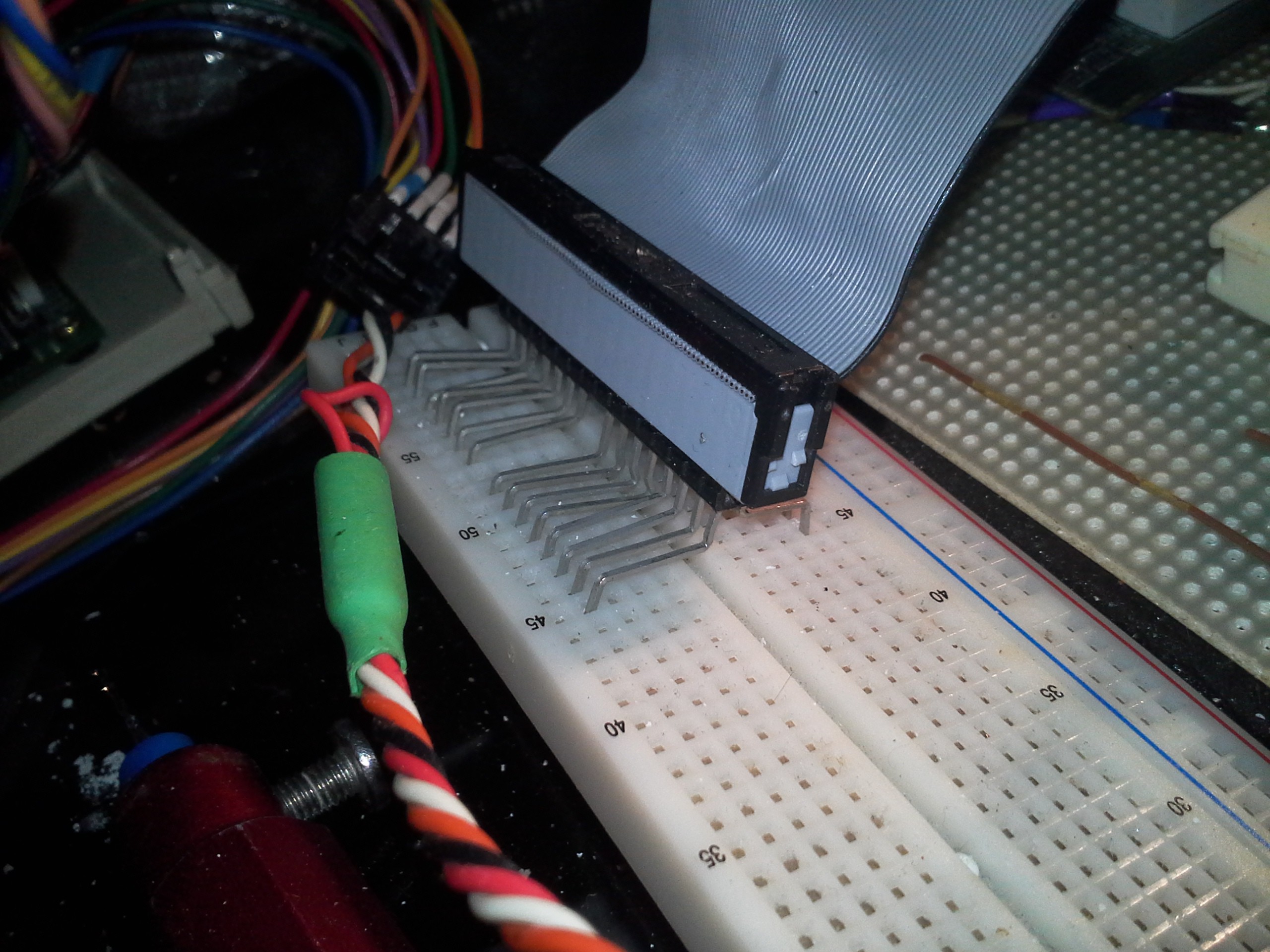
(Heh, if this guy wasn't a right-angle mount, originally, those pins are long enough they probably wouldn't've even had to've been bent to reach the inner two rows... Either way, I don't have any more connectors with pins this long in my collection, that I'm aware of, so we'll stick with this one, for now.)
---------
Oh Hey! I forgot to mention that I'm using the "Flip Pins" for my surface-mount breakout-boards... They're perty-slick! Note how my SOIC-breakouts have the chip *over* the pins... Yeah, it'd've been *much* smarter to solder the pins in before the SOIC chip, but I managed to make it work anyhow, and these pins are *really nice* on breadboards.
Order some! Check 'em out at #OSHChip V1.0
Discussions
Become a Hackaday.io Member
Create an account to leave a comment. Already have an account? Log In.
Wow :-) and with a proper PCB ? ;-)
Are you sure? yes | no
133MS/s, here we come!
Are you sure? yes | no