 Eric Hertz
Apparently it's brain-dump time.
In the previous log I showed my thoughts on making a sorta general-purpose prototype-board that can be used for the first soldered prototype, as well as be used/usable for many other unrelated projects...
Here's the latest fixation... Weee!
What I didn't mention was how this proto-board also looks to the future of *this* project...
This project has two main phases, I see...
First is getting it as fully-functional (sample/repeat, high-speed, trigger, adjustable sample-frequency) as I can... That's easiest done with a uC that has plenty of GPIO pins... Thus I'm using my trusty ol' ATmega8515 40pin-DIPs... and, as I described in the last log, that lays-out perfectly over some otherwise currently-unnecessary breakout-space on my protoboard-design...
The second phase is replacing the dedicated AVR in favor of whatever host one might want to use... e.g. a single-board computer like the Raspberry Pi, or even via an FT2232 chip connecting it directly to your computer via USB. The hurdle, here, is that this requires whittling down the number of required GPIOs to something reasonable... like an 8 or 16-bit data-bus.
There's plenty of contemplation in my various logs regarding how I'll do that, and I don't doubt that I've got it mostly-figured-out... I could probably, if my brain works in my favor for that long, whip it out in less time than it'd take to receive this PCB order.
But, I guess, I tend to take an iterative-approach with my projects, rather'n going gung-ho with a design->PCB... And, the current scenario is that the solderless-breadboarded prototype has become increasingly-flakey (largely, I'm sure, due to wires getting bumped, "antennae" everywhere, etc...(interestingly, when I run it at 50MHz, it interferes with my TV reception!))... The likelihood of this guy lasting a year and being able to just power it up and make use of it is... pretty low.
So, iteratively, I still have a bit I could experiment with and implement while connected to an AVR... and, I wouldn't mind having a reliable prototype that I can come back to later down the line and turn on and expect to still work.
-------
Oy, all that explanation to say... no, I haven't forgotten about the second-phase, in this proto-board's design.
Whittling down the GPIO-necessity is mostly just a matter of a bunch of latches... and low-and-behold, I've laid out this board for two 8bitters... Right under where the AVR goes, currently. And, again, I'll be using *two* of these boards for a single DIMM, so I'll have four 8bit latches available and broken-out. And, again, I've laid out SOIC-breakouts as well, 20pinners, which will also work for 74xx574 latches. So... I think we're set. And if not, then I can just as easily throw a third board at it. (Yay buying in quantities!)
In fact, who knows, I might just bypass the AVR soldered-proto... It's plausible. I do have a PiZero and now also an LCD with HDMI, after all! And I plan to order an HDMI cable/adapter alongside this PCB-order... So, who knows.
--------
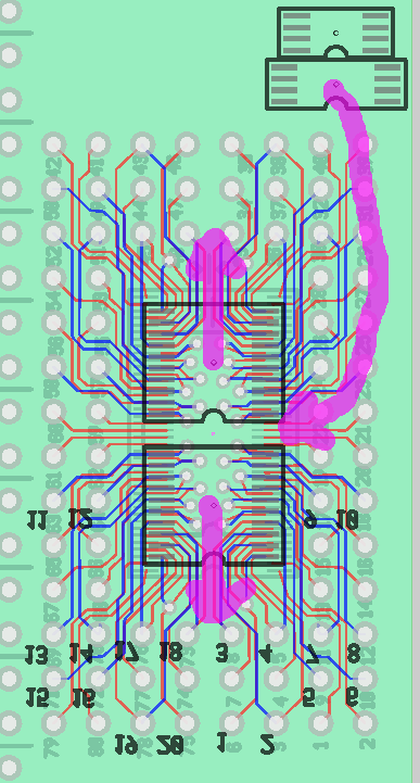
The image above shows the current state of the 574 breakout(s)... It wasn't easy fitting them in there, being that the other side is a TSSOP-80/56 breakout, but it wasn't particularly difficult, either. It was easier than I expected, though. A pleasant surprise, for sure.
I *think* I might be able to squeeze that 8-pin TSSOP in between, but that might be almost as much work as the two 20pinners, and plausbly not possible, due to the number and positions of the vias and the red-traces necessary for the current setup.
The idea, there, is to throw in the clock-generator chip... (also explained in previous logs)... That guy basically allows one to select from a huge selection of clock-frequencies anywhere from 500Hz to 200MHz (thus, sample-frequencies). Could be quite the gizmo, and I haven't yet experimented with it.
(Also, it requires I2C, which I'm not expecting the "host" to provide, meaning I might be implementing it via bit-banging via the host-interface, or something).
----
TODO: Believe it or not I did all that layout without actually verifying the chips I have match those footprints. Usually that'd be the *first* thing I'd do... Usually I'd make my own, in fact, because I rarely trust those provided. This time, for some reason my brain's been on this tetris-style packing-kick. Could be risky. I guess we'll see. I can feel the datasheet-lookup energy building... may be a few days. Or maybe I'll just print the danged thing and set my chips on the printout.
----
Anyways, all that to say, of course this project is still aimed at more powerful hosts than this lowly AVR. And of course I'm keeping that in mind while developing this protoboard. These things develop the way they do...
Discussions
Become a Hackaday.io Member
Create an account to leave a comment. Already have an account? Log In.