THE DESIGN PROCESS
I've always wanted to build a rotating POV display, and had gone so far as to order some surface mount LEDs, but never came up with a satisfactory method to transfer power to the rotating part. With the availability of the Pi Zero my interest was revived, so I decided to compromise and mount a battery along with the Pi Zero as a workaround. Then I ran across this kit which prompted me to do my usual design review.
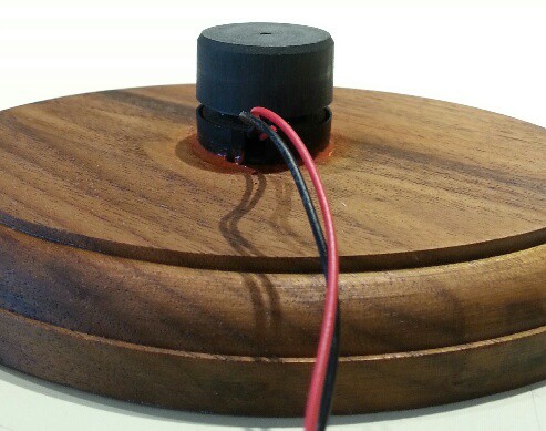
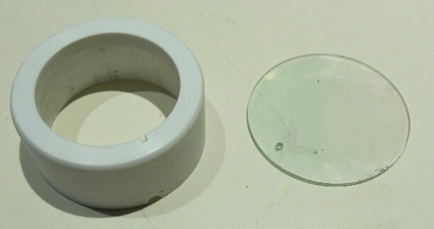
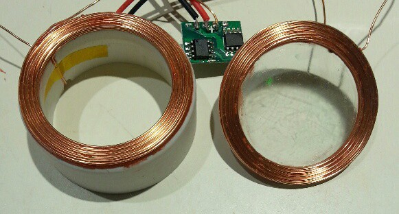
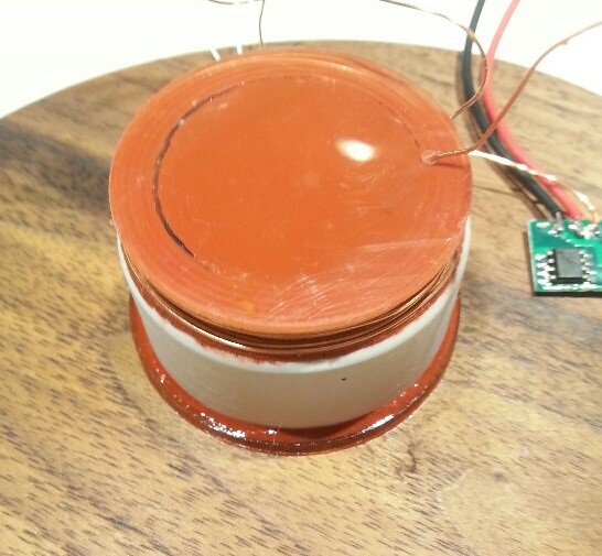
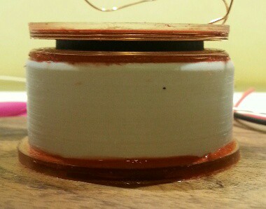
First I looked at the power transfer. The kit uses a rotary transformer, made up from a large ferrite bead and hand wound coils. I was NOT looking forward to winding coils and making driver circuits. Then I realised I already had a complete solution on hand - an Adafruit inductive charging set I'd bought for another project. Problem solved!
The motor looked like a cheap brushed type, and I didn't think it would last long in use, so I decided to replace it with a brushless one. Candidates included the spindle motor from a hard disk, the spindle motor from a CD drive, or a brushless DC fan. The hard disk motor would interfere with the charging set (the hub is aluminum), so it was out. The CD motor would work, but I'd have to buy a $7.00 ESC to drive it. I was left with the fan. I was worried about the lack of ridigity, but after some testing it seemed OK.
I didn't need the top display, so that could be eliminated. I could eliminate the chip resistors and instead use leaded resistors from the LED board to the Zero's gpio holes. These would also hold the board rigidly to the Zero. The board would be quite easy to design and should cost under $5.00.
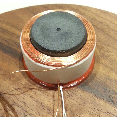
Holding the coils in position should be easy, and the Zero would mount on top of the rotating coil. I decided to test later to see if the magnetic field from the coil will induce any harmful currents in the Zero. If it did it would always be possible to shield it.
The Zero would be mounted off-center to make the display diameter as large as possible. As in the kit it would need some counterweights, but those could be easily attached to the Zero mounting holes.
The IR sync method of the kit should work, and the parts for it could probably be salvaged from a mouse scroll wheel. Bluetooth could be used instead of the IR remote.
Existing Python POV software should work, or I could write a kernel module using DMA.
All sorted. Time to build it!
NAYSAYER NOTES: Yes, this will cost a bit more than the kit. But I wouldn't learn anything that way except maybe some soldering practice (which I don't need), and how to use the Arm programming environment provided with the kit. Frankly, I'd rather write my own code in a familiar environment instead.
 Ace
Ace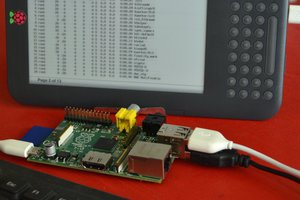
 j0z0r pwn4tr0n
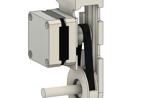
 Adam
Adam