 hayden
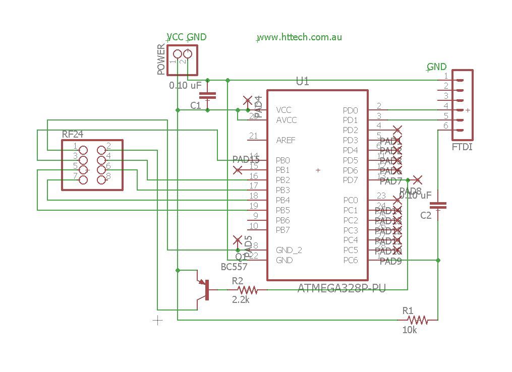
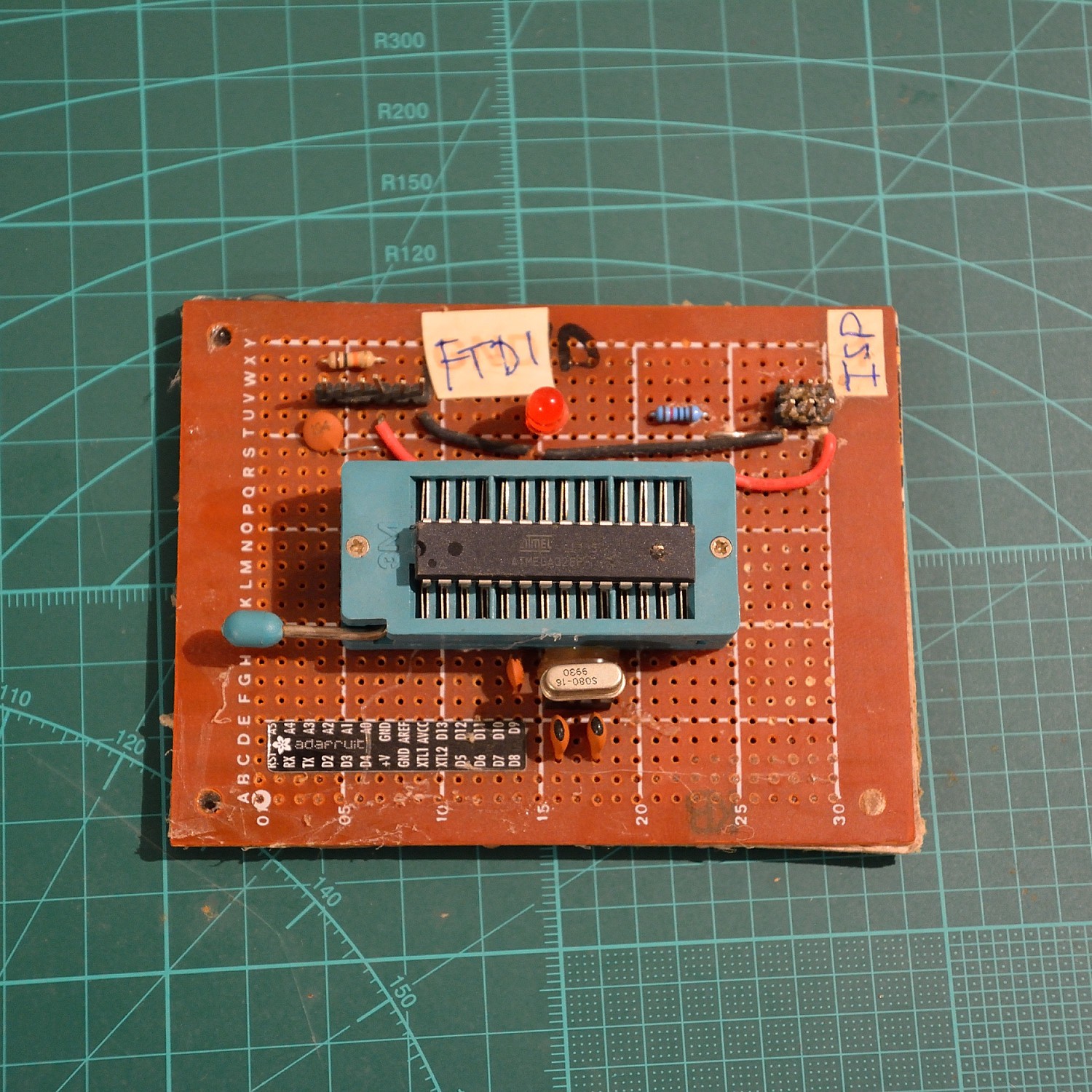
- The Arduino 328 chip has boot loader for ftdi & fuse settings to set low voltage protection to 1.8v & run at 8Mhz via the internal oscilator (avr programmer reuired.)
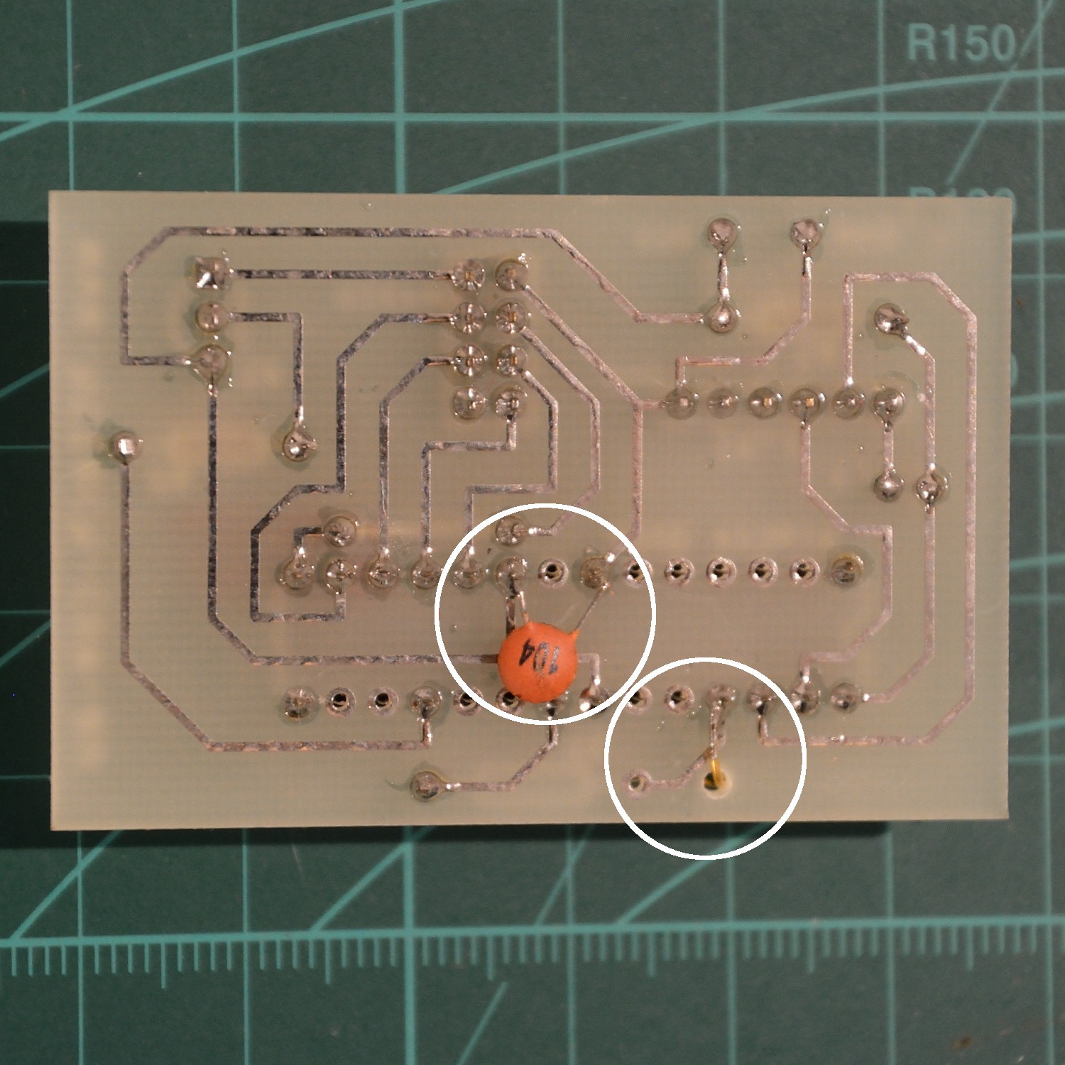
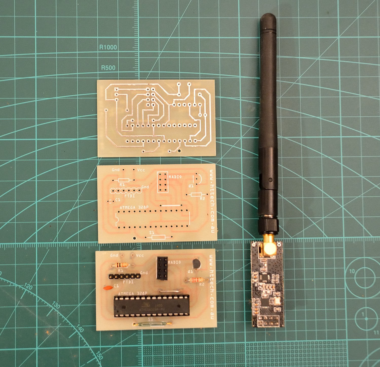
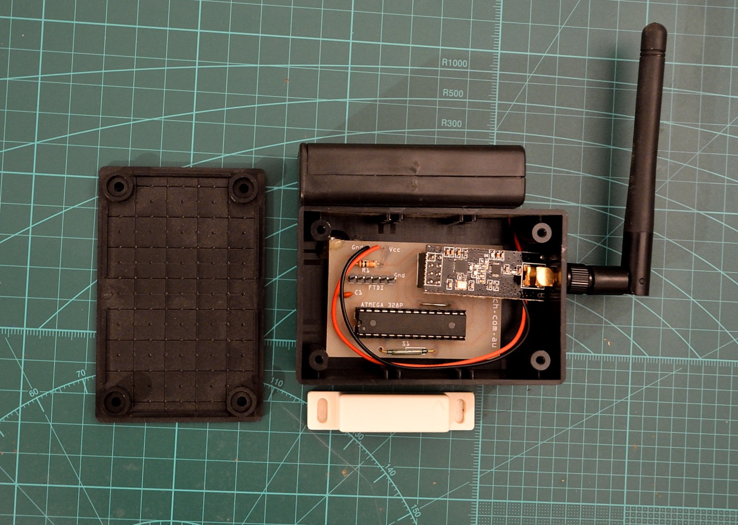
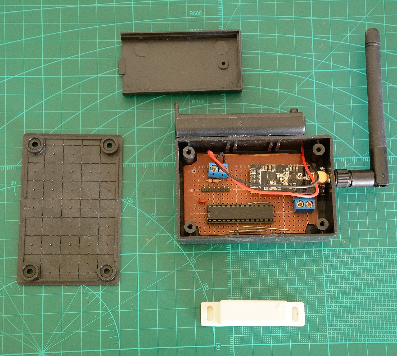
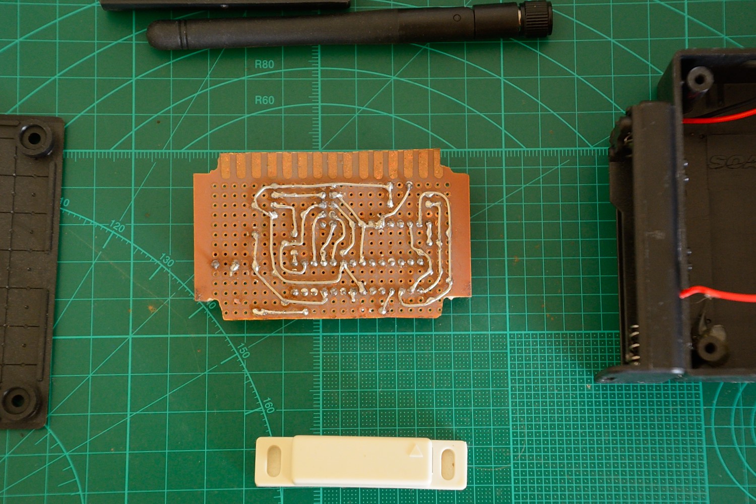
- Version 1 i have had produced and you see in the photos, this was my first pcb run, and there where a couple of minor problems, my reed switch had a wider whole spacing, and i needed to add a 100nF ceramic capacitor across the 328's vcc/gnd to smooth its voltage.
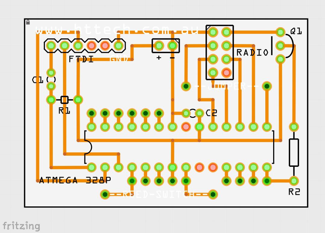
- Version 2 has some improvements, though i have not produced it.
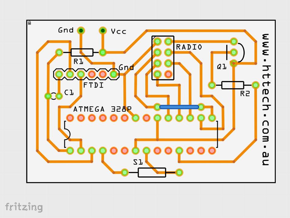
- Version 3 has been converted to Eagle, ive dropped the reed switch spot, relocated the rf24 switch transistor out from under the radio, and changed radio wires/routing to eliminate need for jumper.
0%
0%
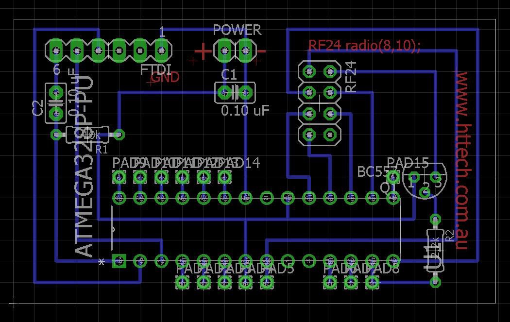
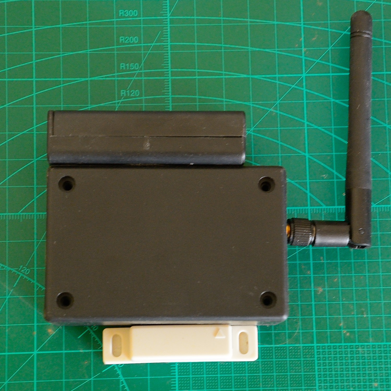
Single Layer Through Hole Arduino 328 & NRF24 PCB
Minimal, Long Range, Low Voltage, Long Life, with switchable RF Vcc
Become a Hackaday.io member
Already have an account? Log in.
Just one more thing
To make the experience fit your profile, pick a username and tell us what interests you.
Pick an awesome username
hackaday.io/
Your profile's URL: hackaday.io/username. Max 25 alphanumeric characters.
Pick a few interests
Projects that share your interests
People that share your interests


 Tom Goff
 ElectroBoy
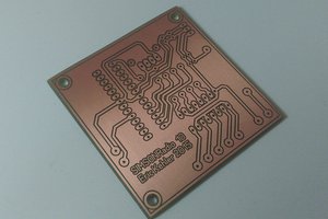
 Smikey
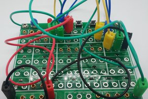
 Tinkers Projects
What method did you use to print the silk screen on PCB?