0%
0%
Used Cell Phone Orchestration
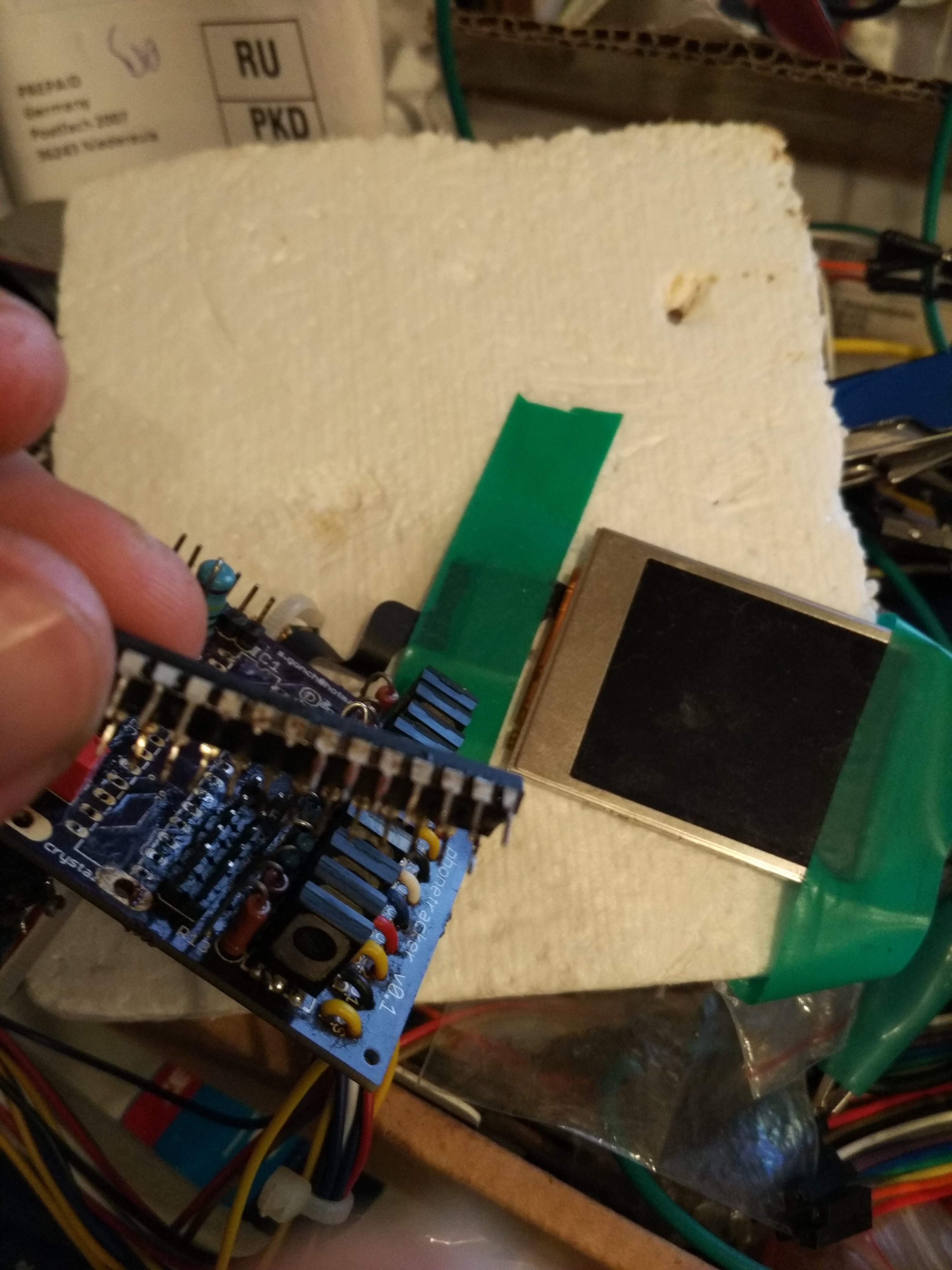
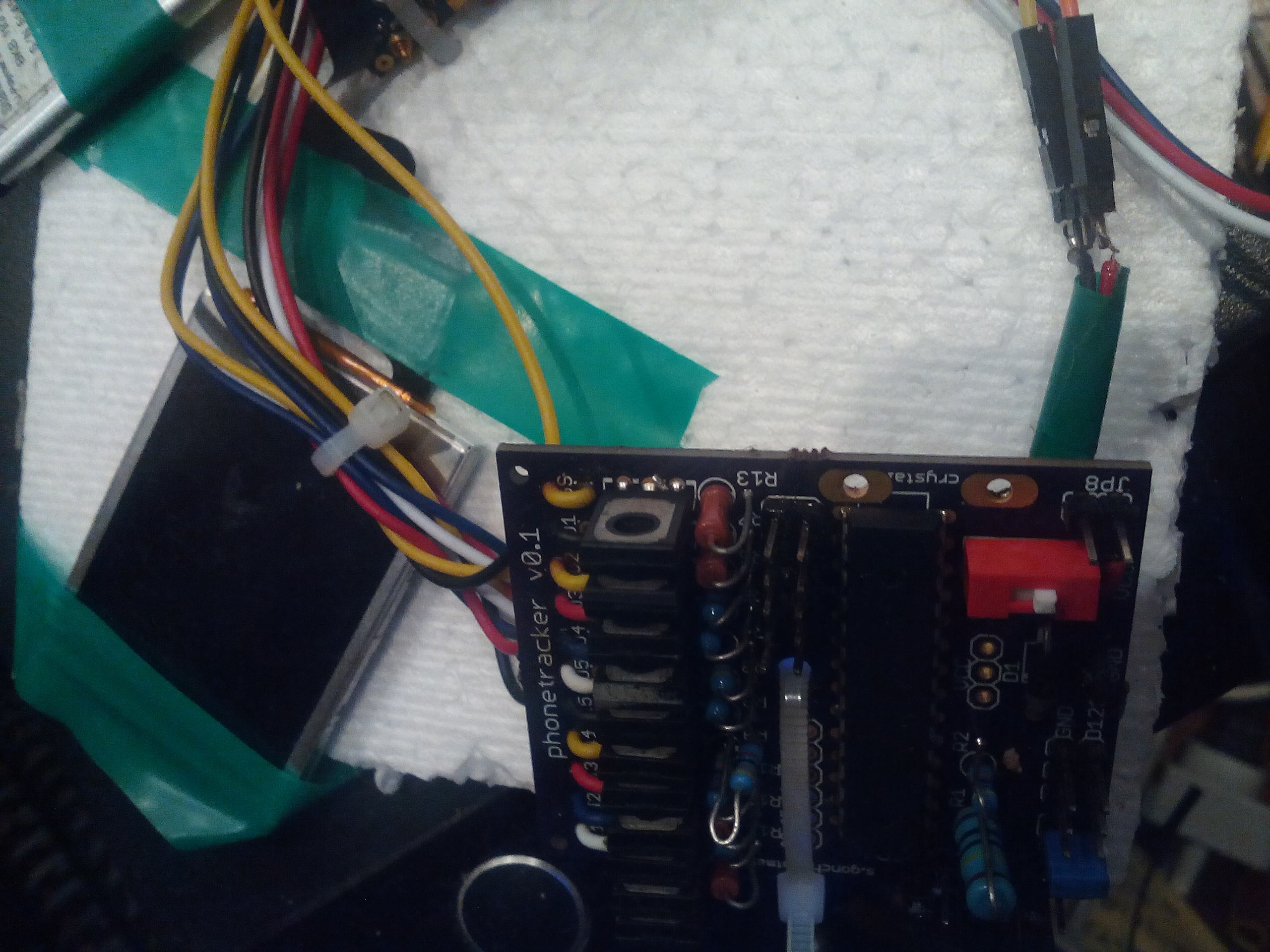
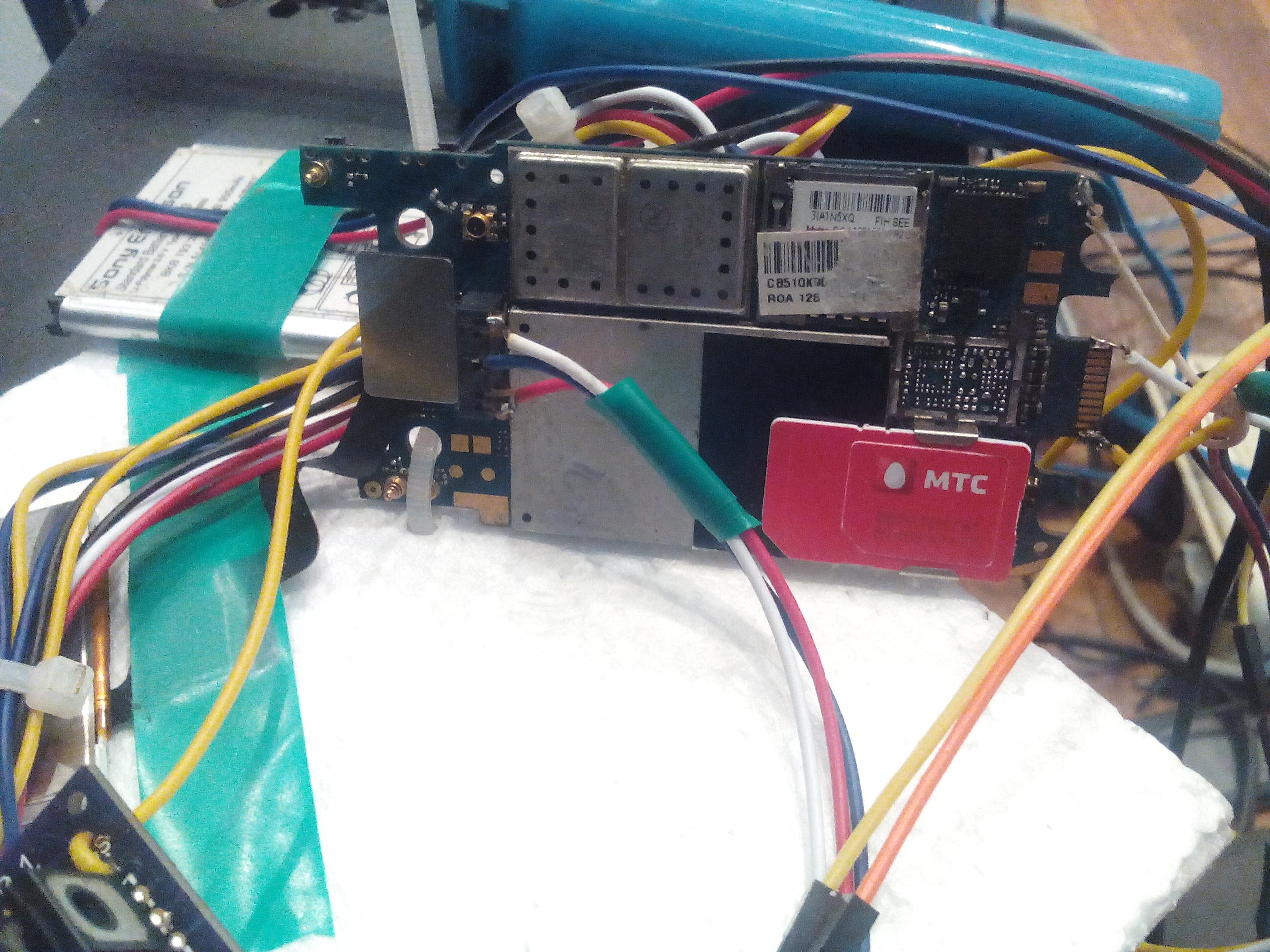
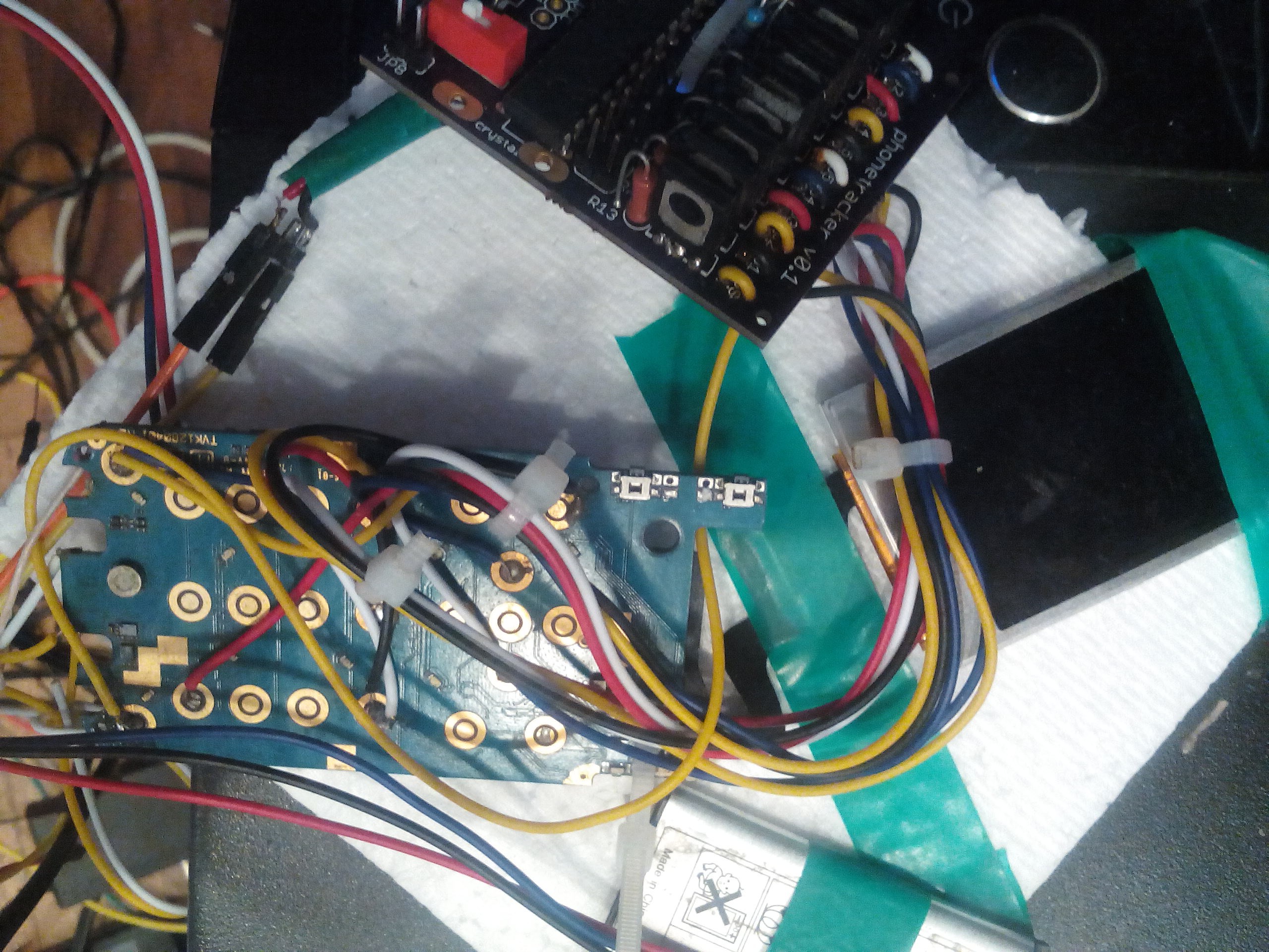
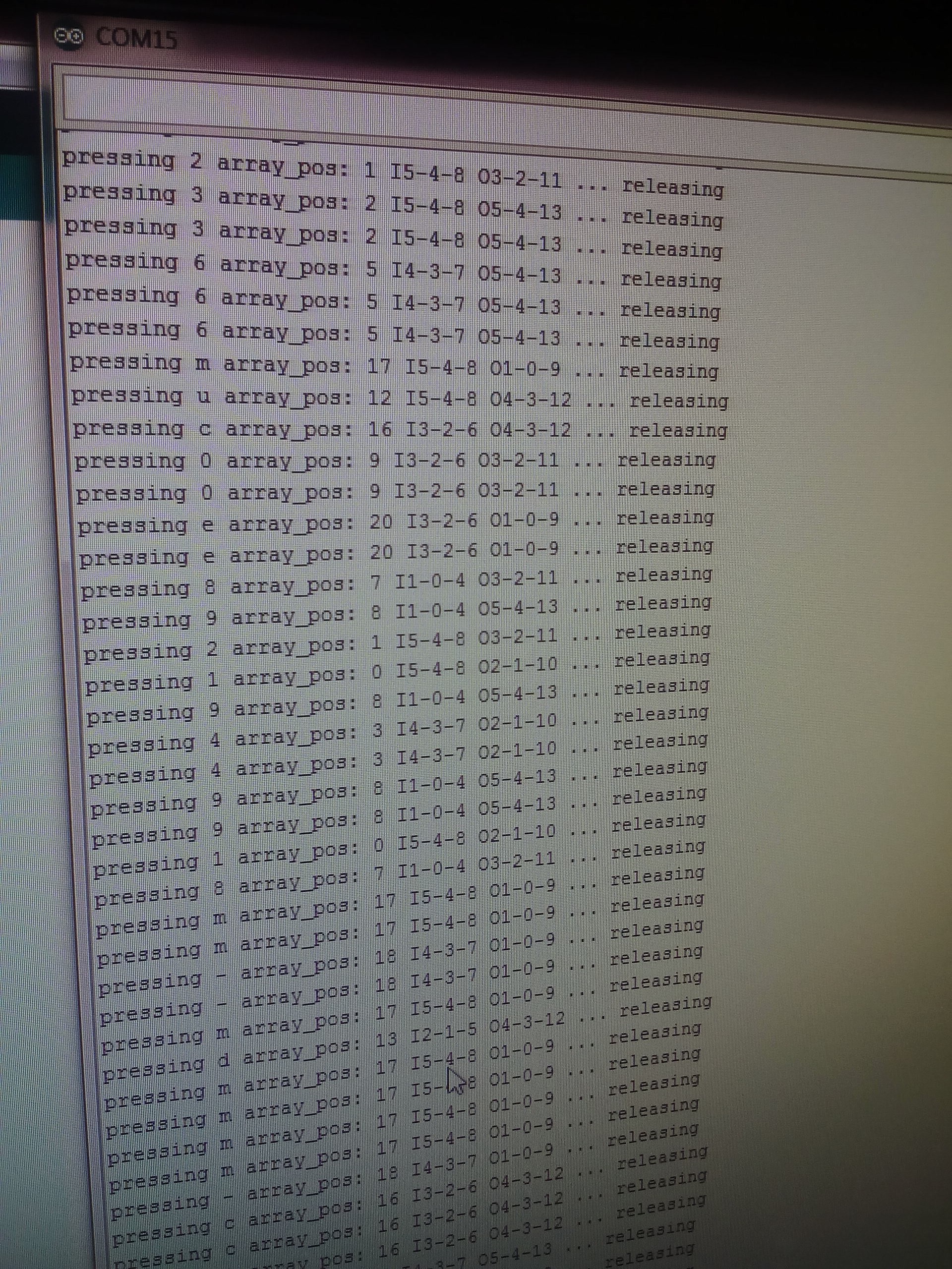
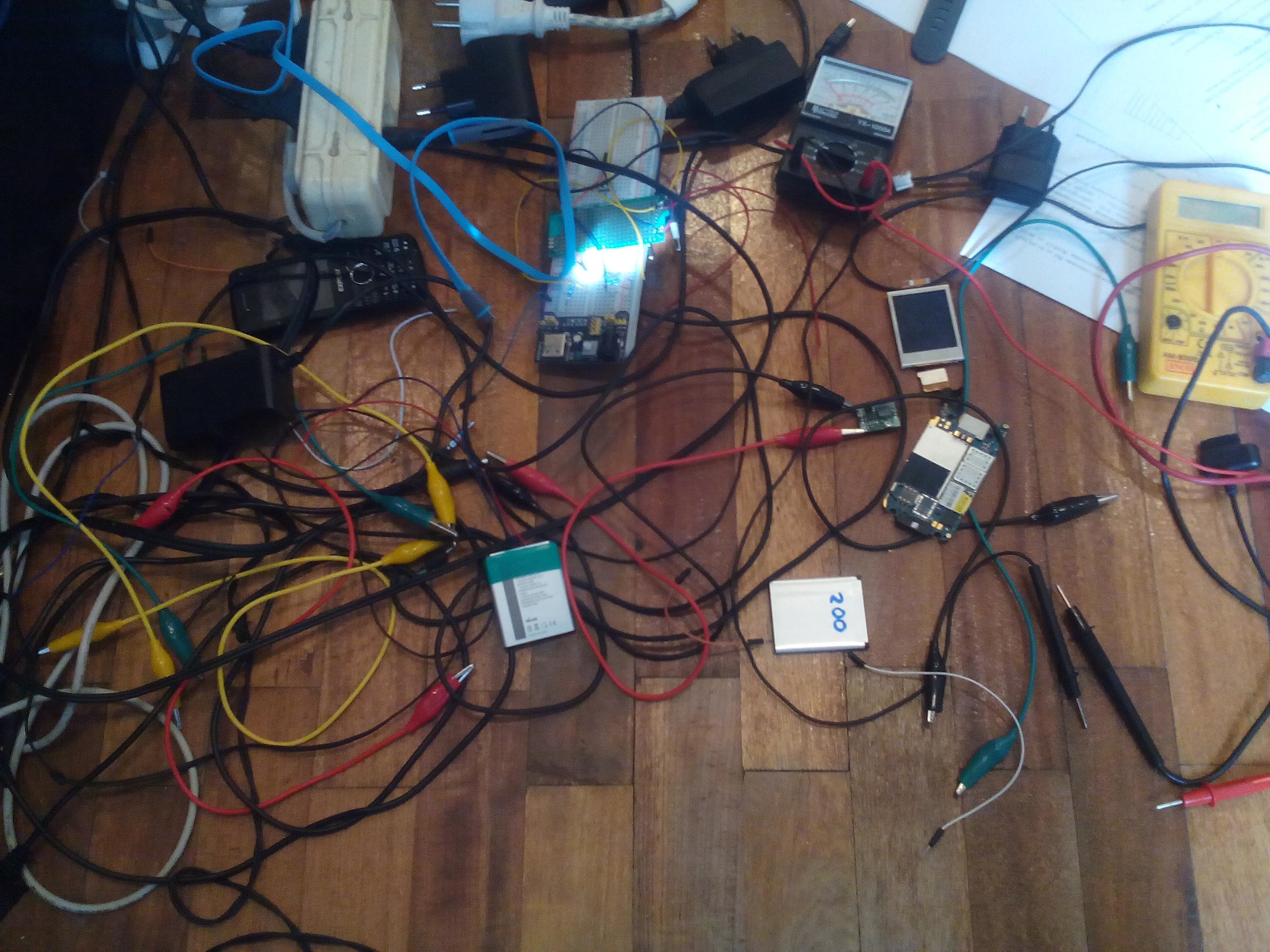
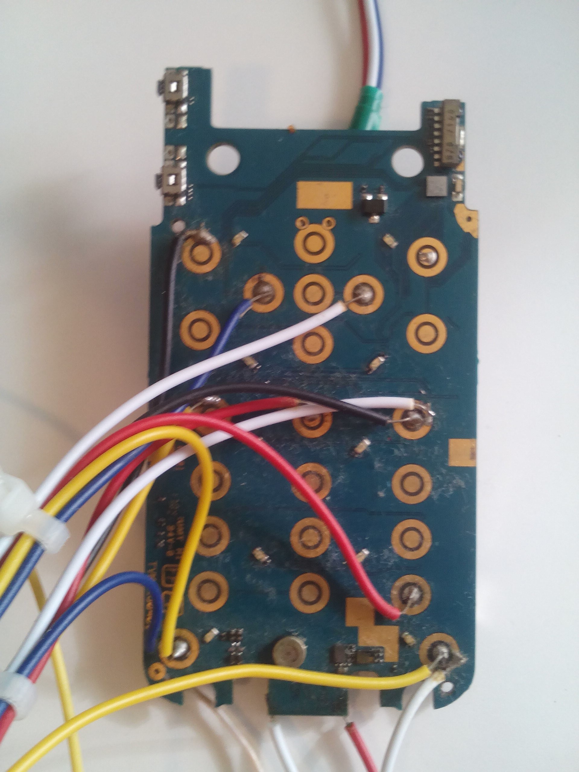
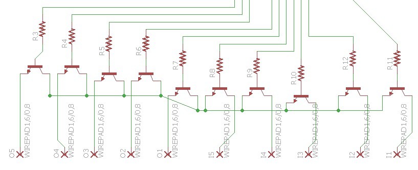
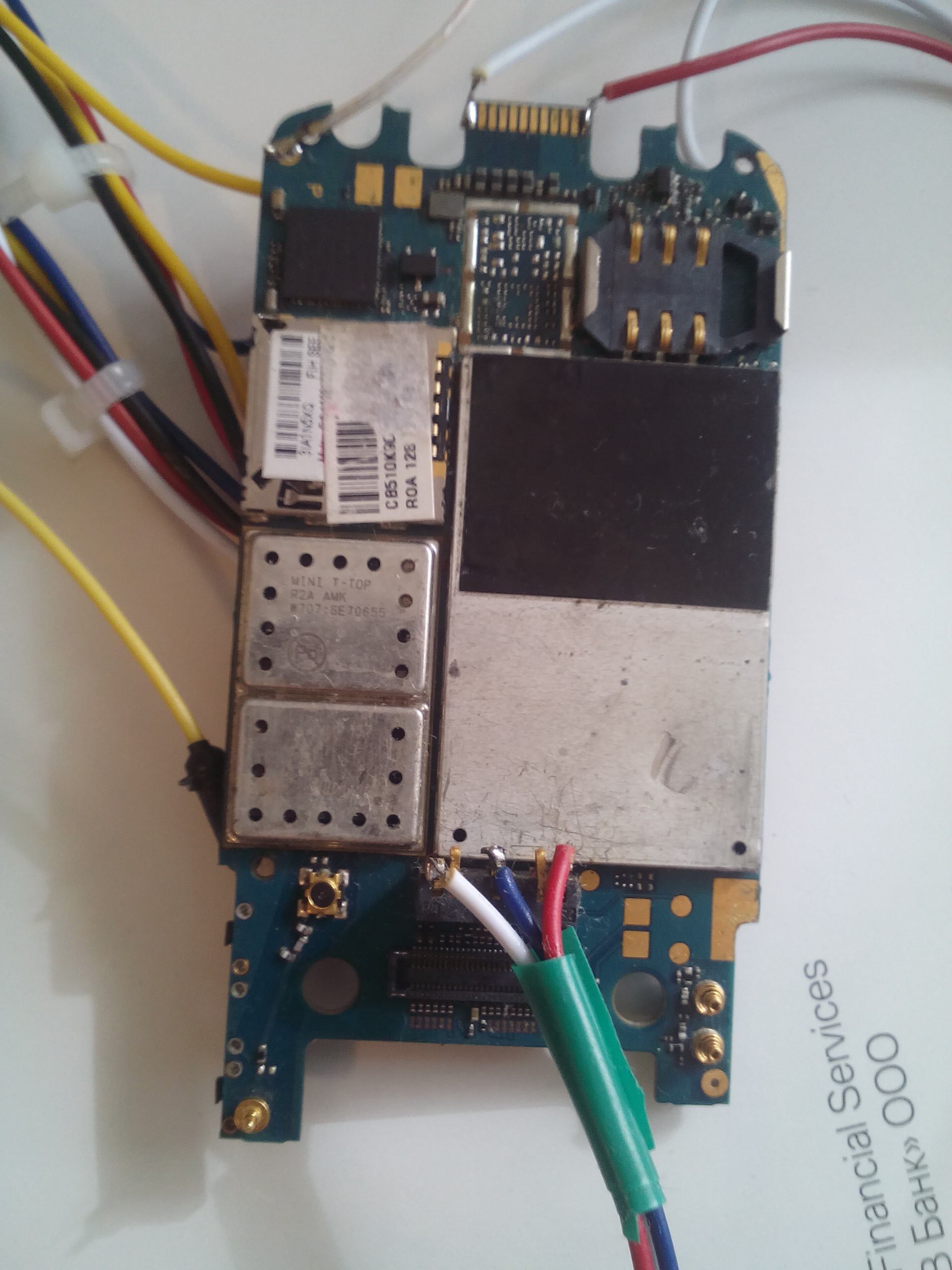
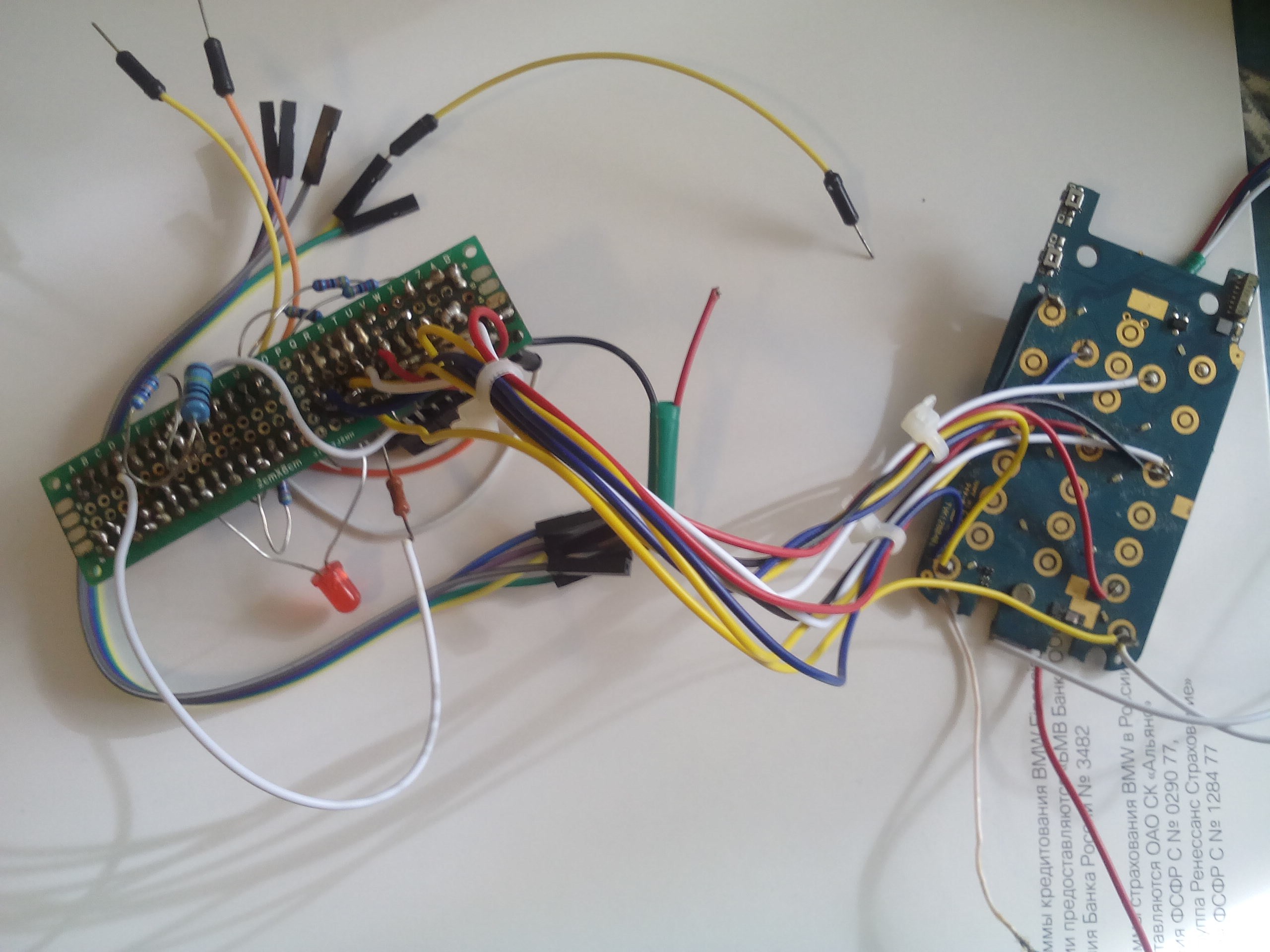
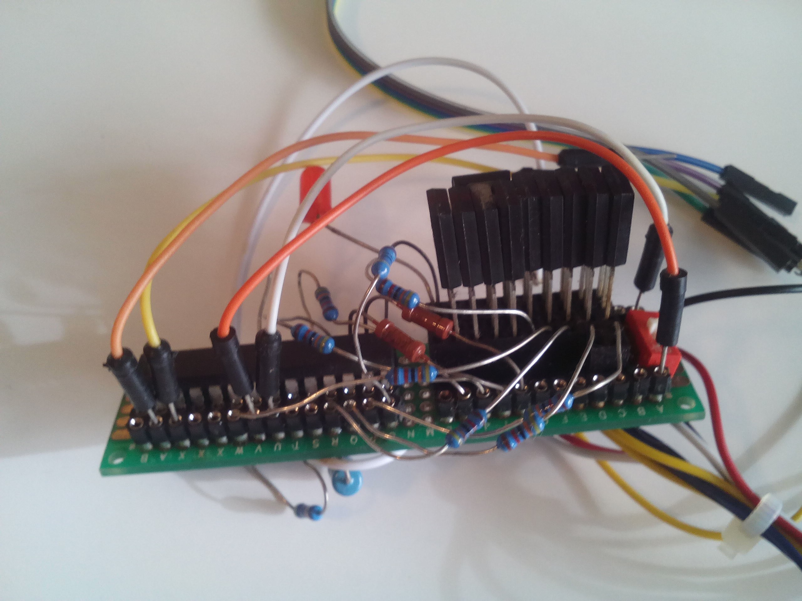
Atmega-based PCB to control Cell Phone keypad. Can be programmed to perfom any phone operation (call, sms, photo, web)
 Sergey
Become a Hackaday.io member
Already have an account? Log in.
Just one more thing
To make the experience fit your profile, pick a username and tell us what interests you.
Pick an awesome username
hackaday.io/
Your profile's URL: hackaday.io/username. Max 25 alphanumeric characters.
Pick a few interests
Projects that share your interests
People that share your interests
 Jeff Cooper
 Nikos
Nikos
 charliex
 blinkingthing