 Mike Rigsby
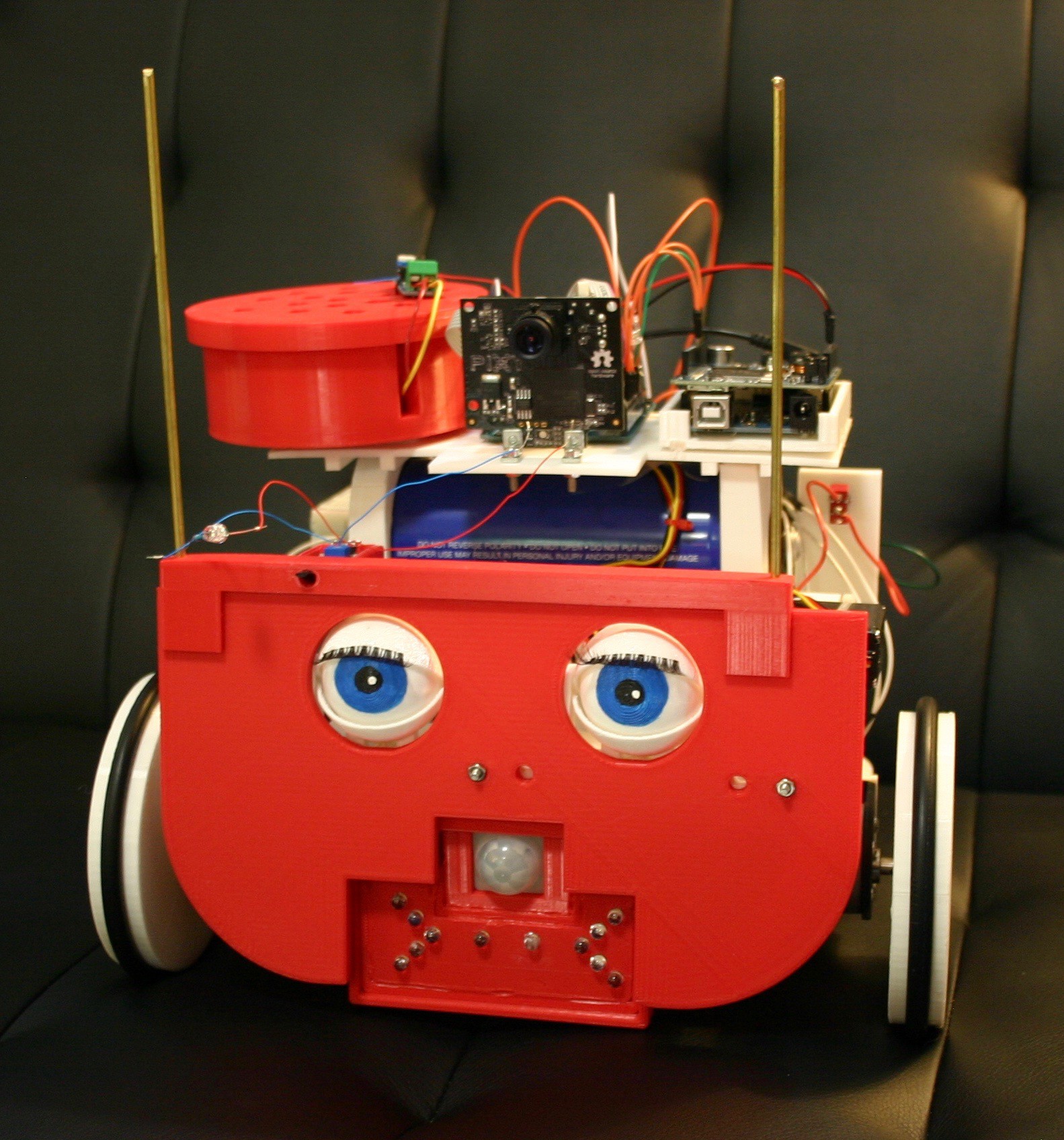
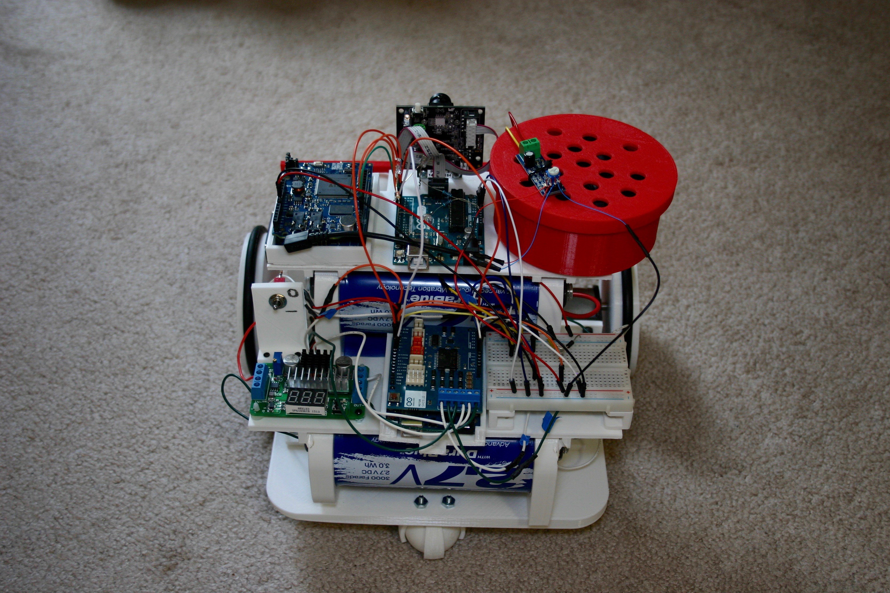
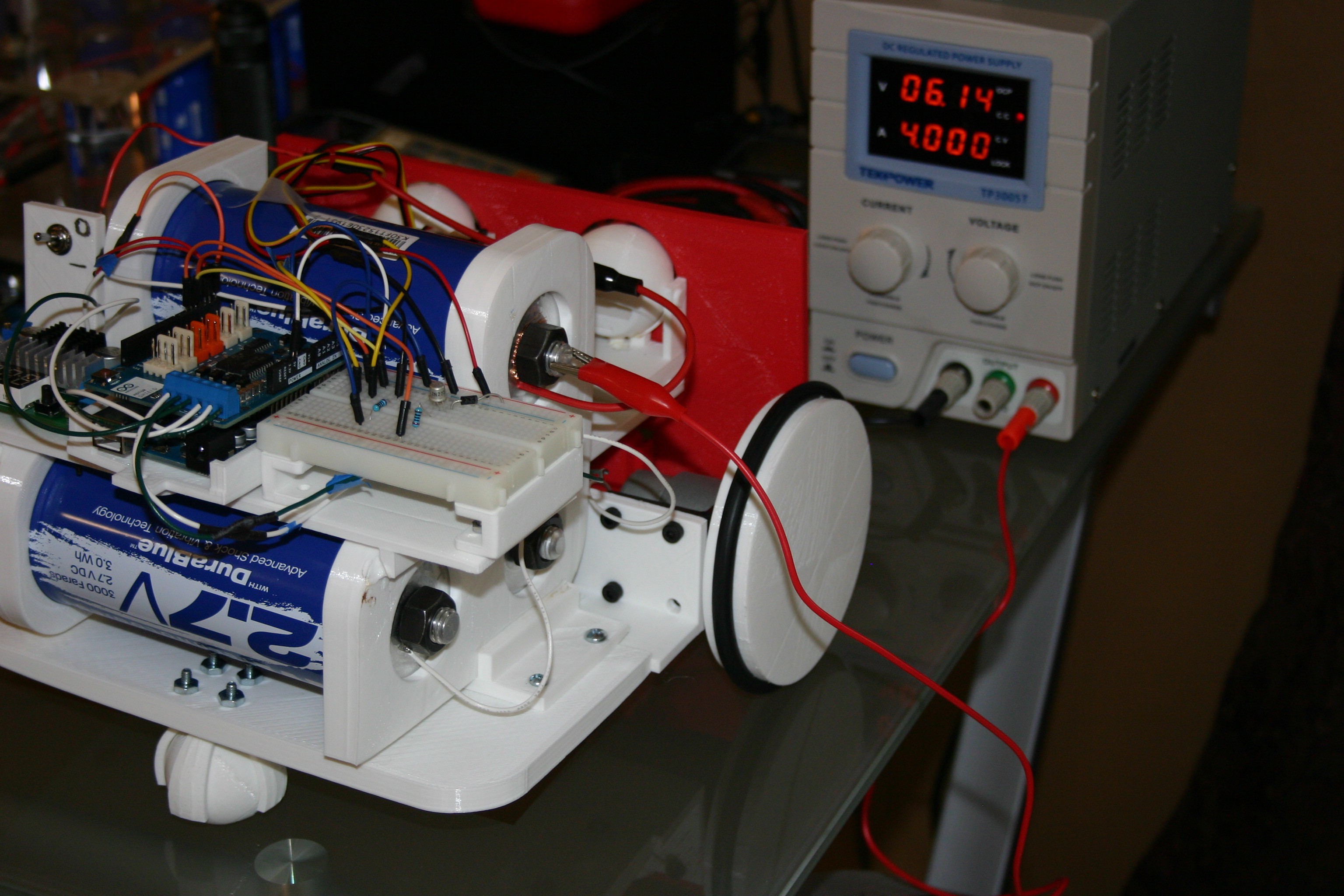
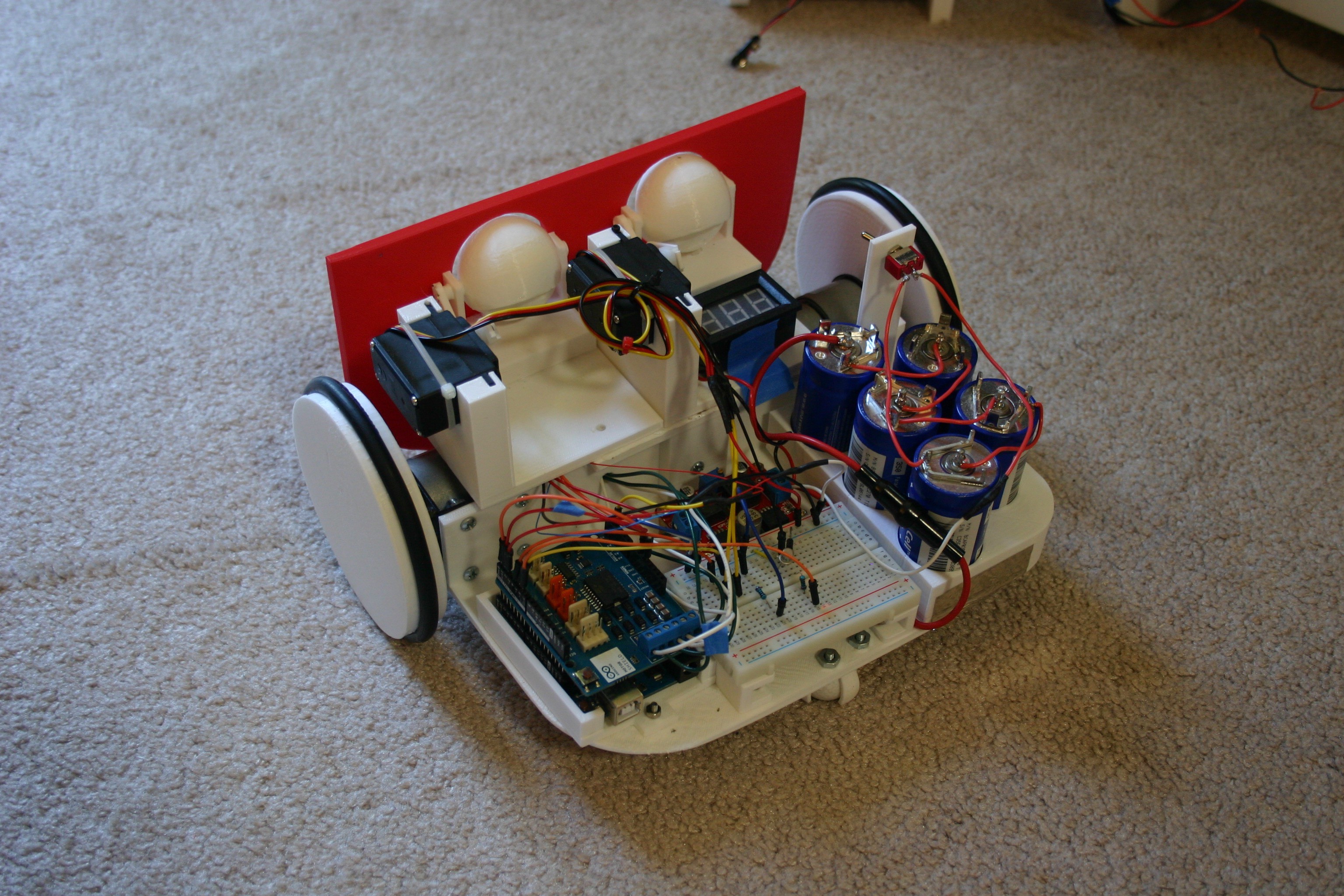
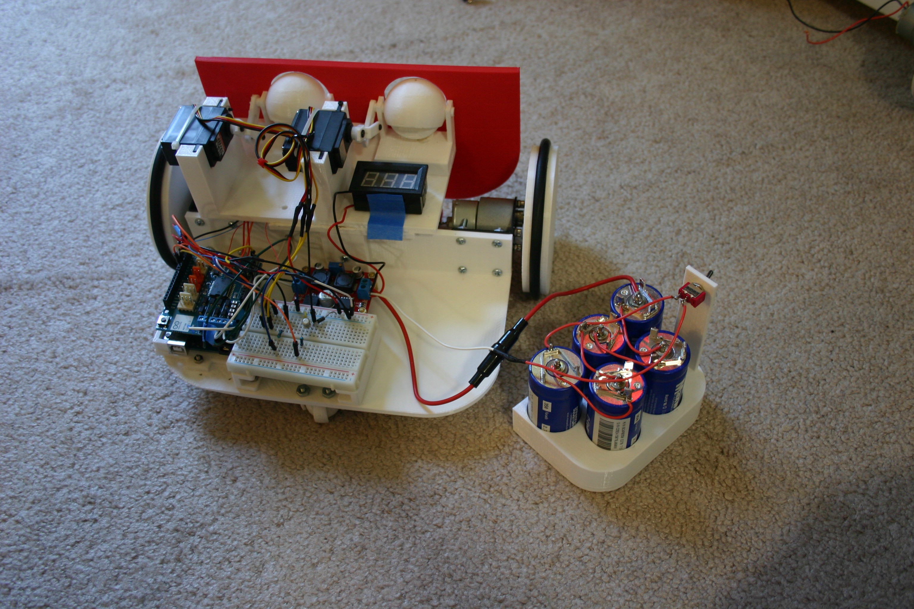
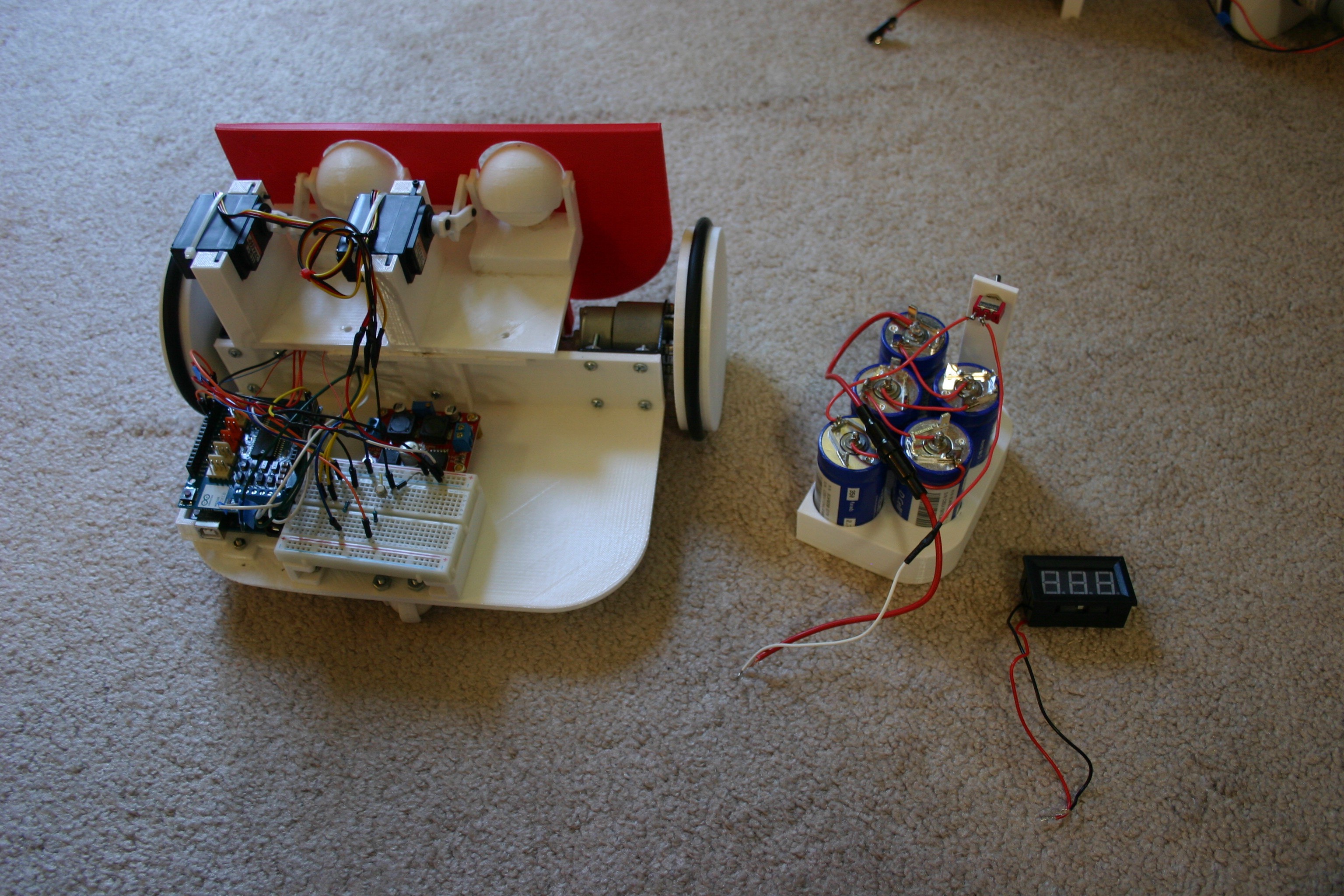
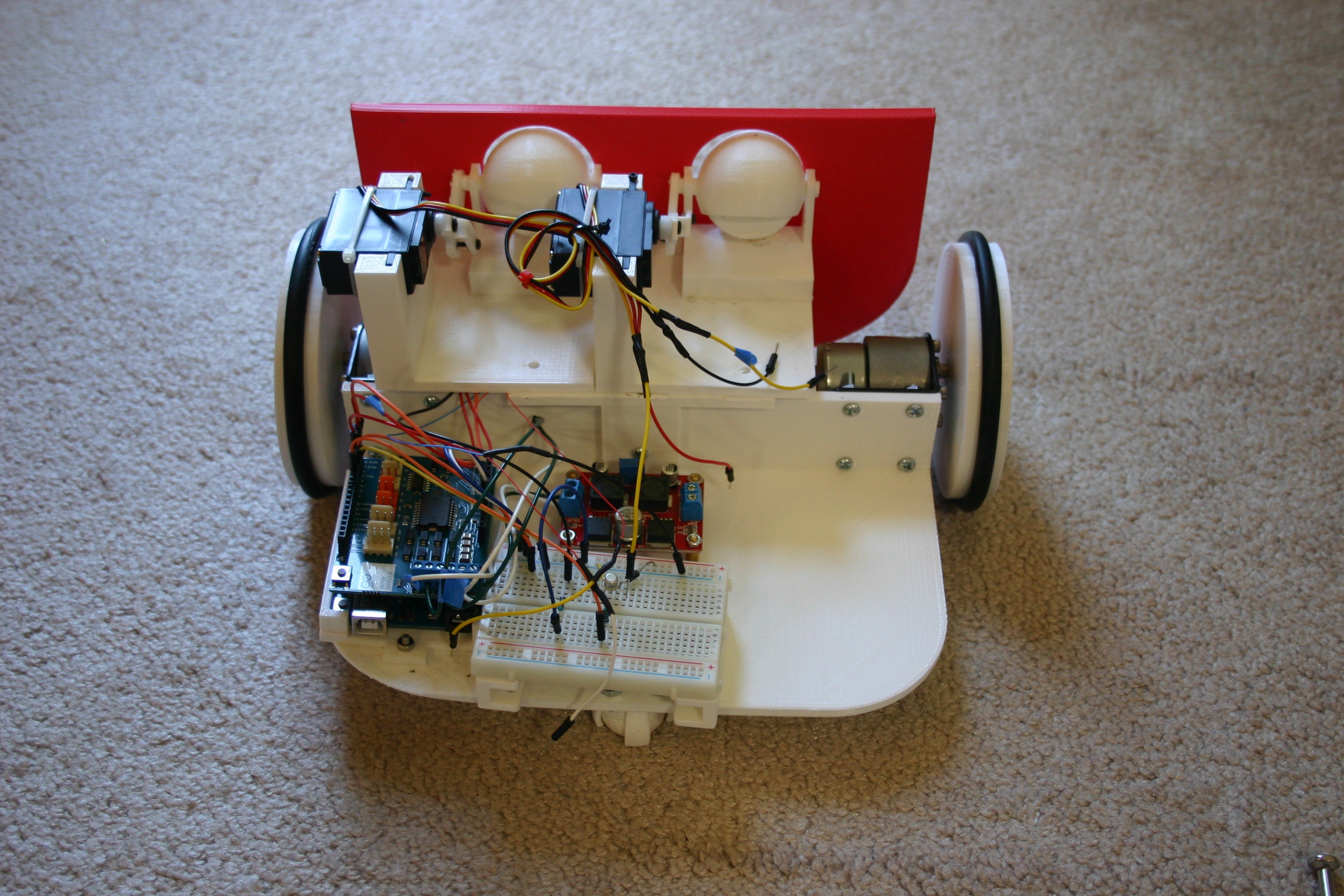
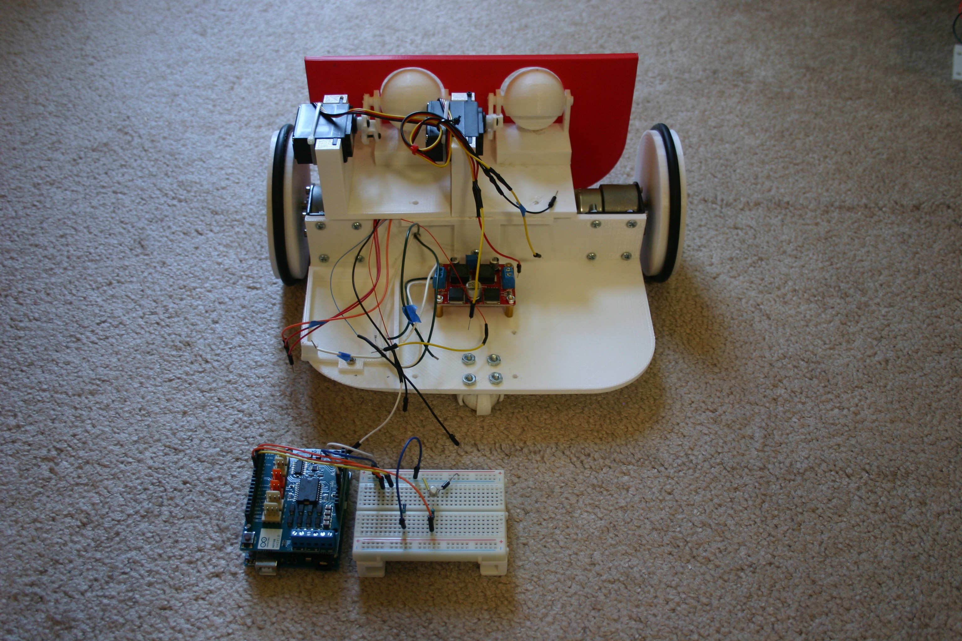
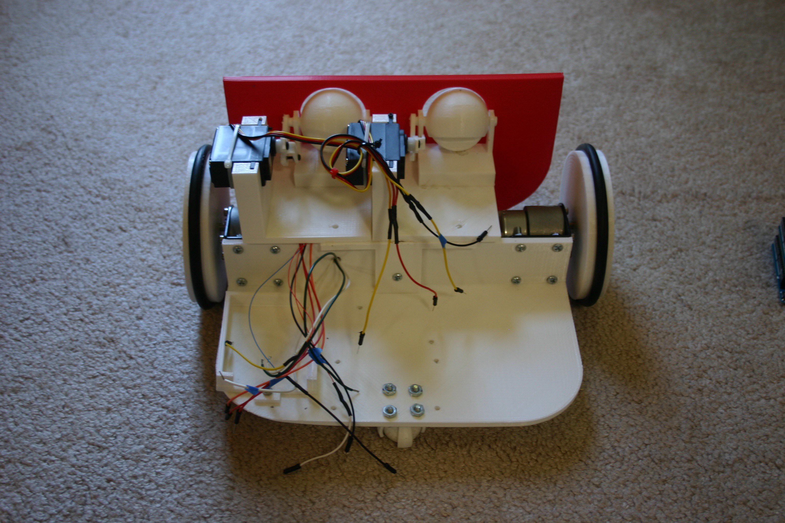
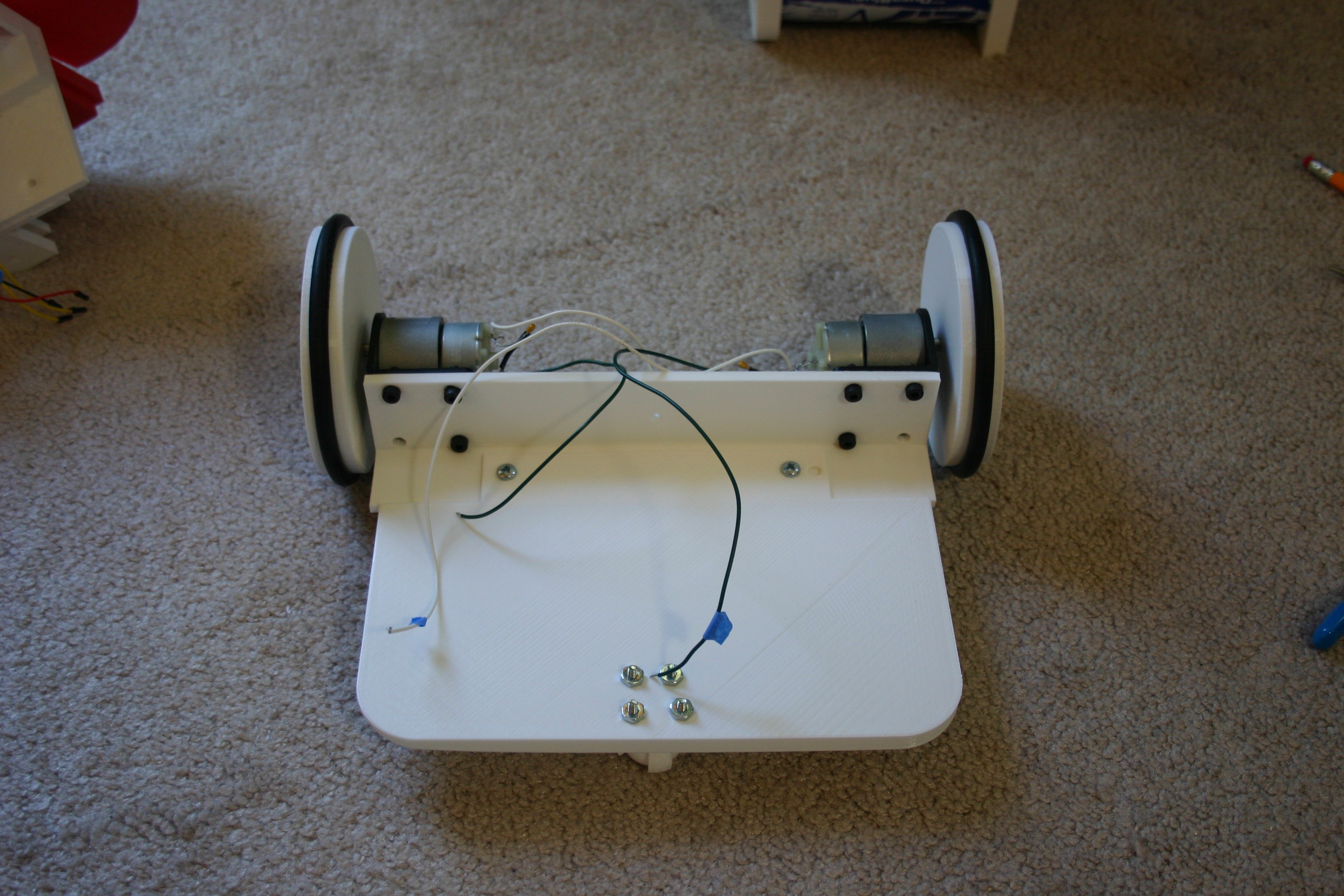
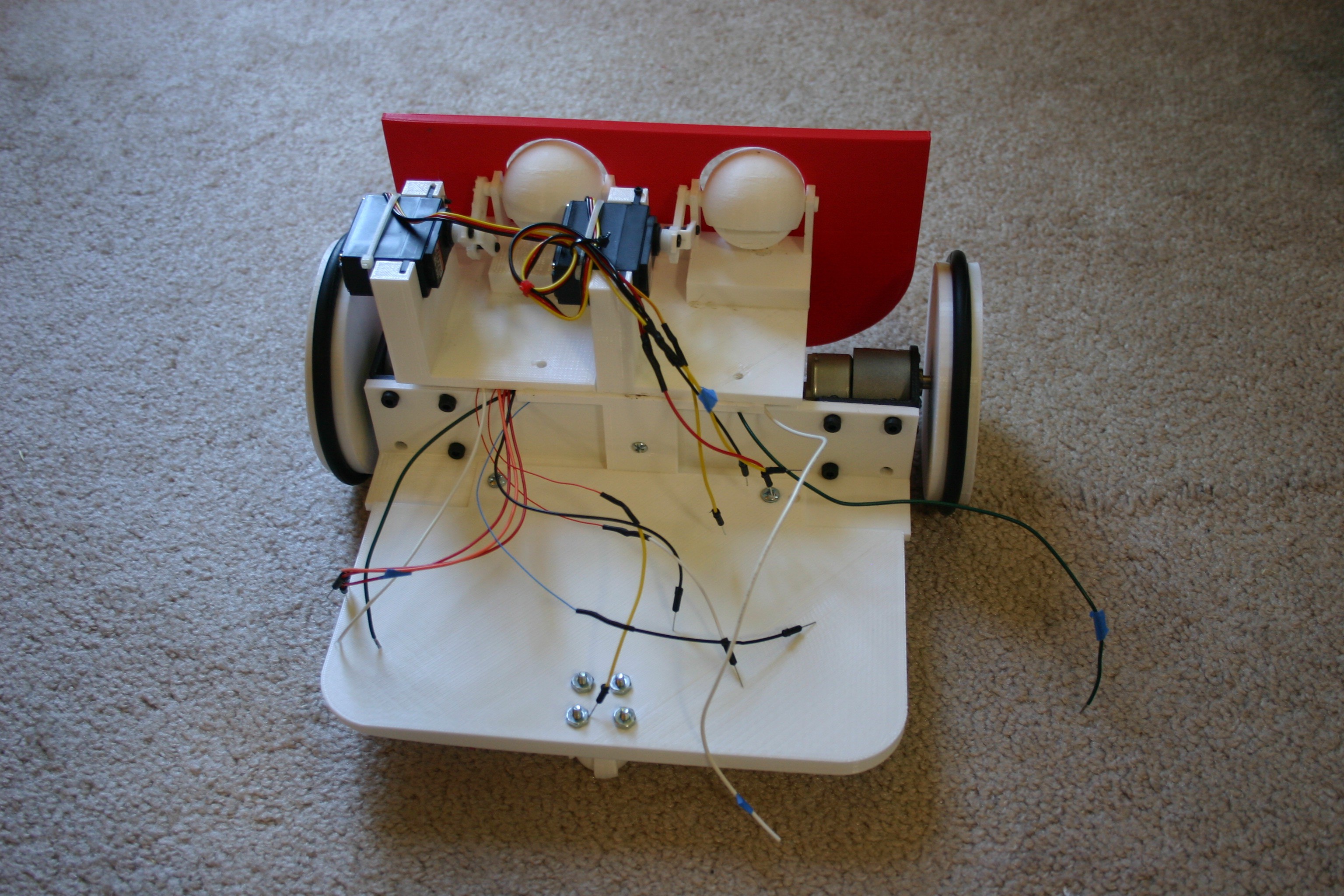
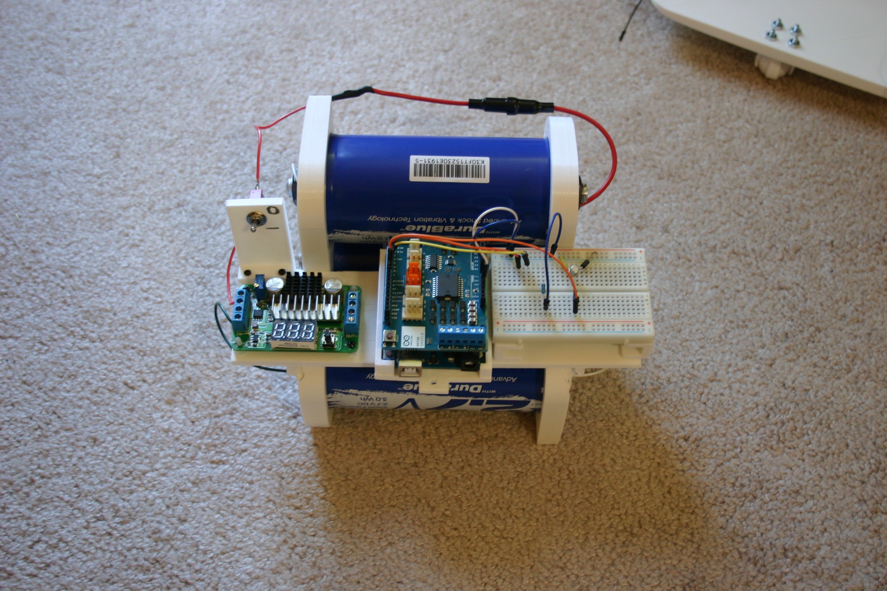
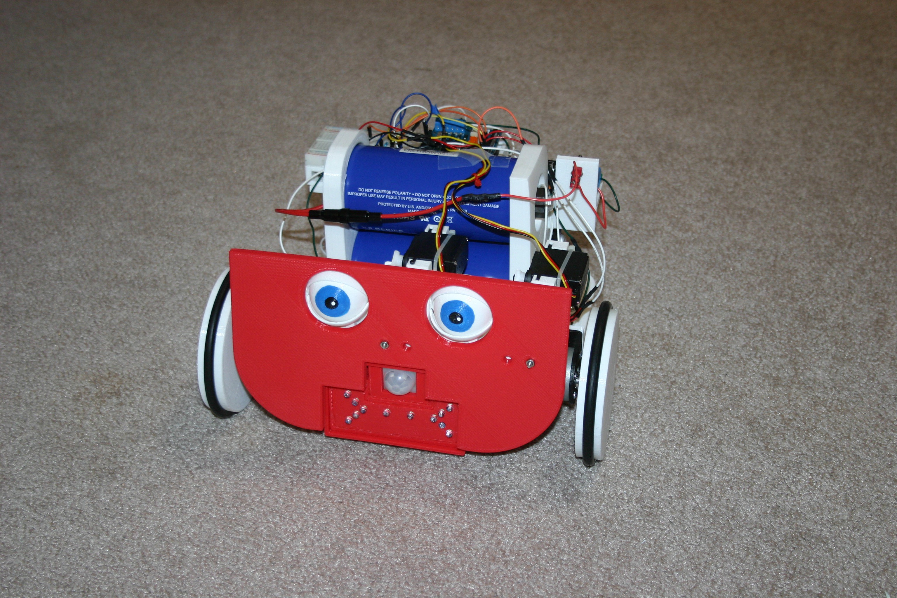
Using three 3000 farad capacitors and a 3d printed chassis, this robot can move around for about 75 minutes on a charge.
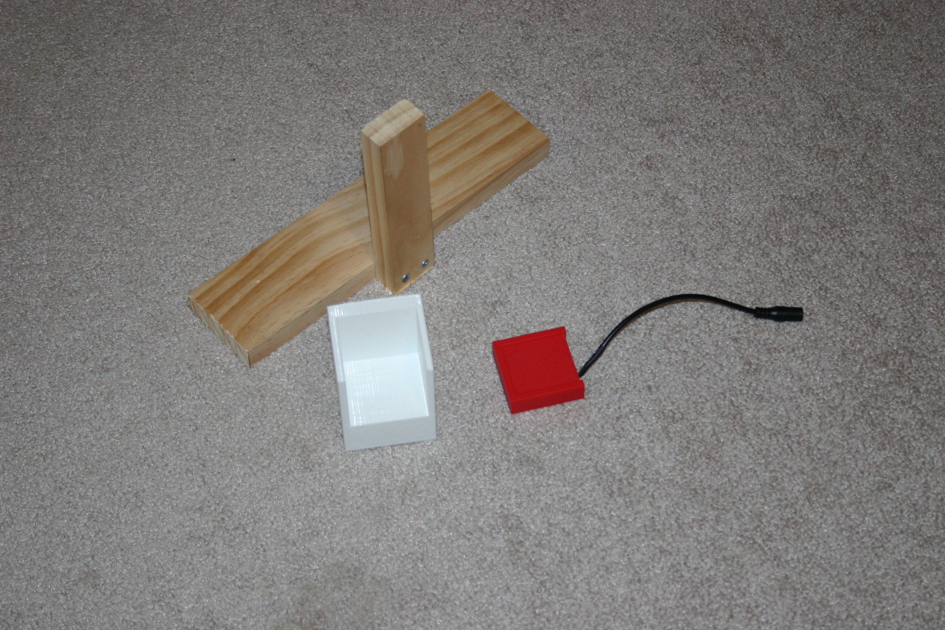
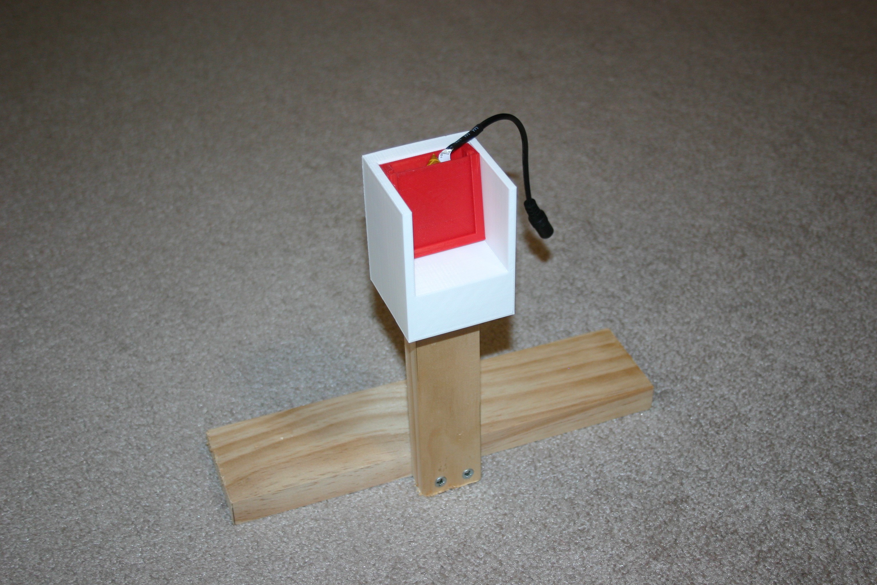
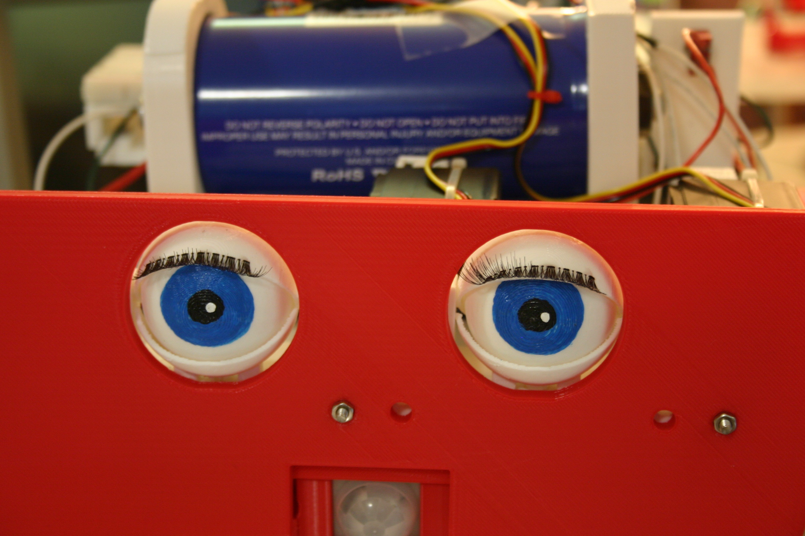
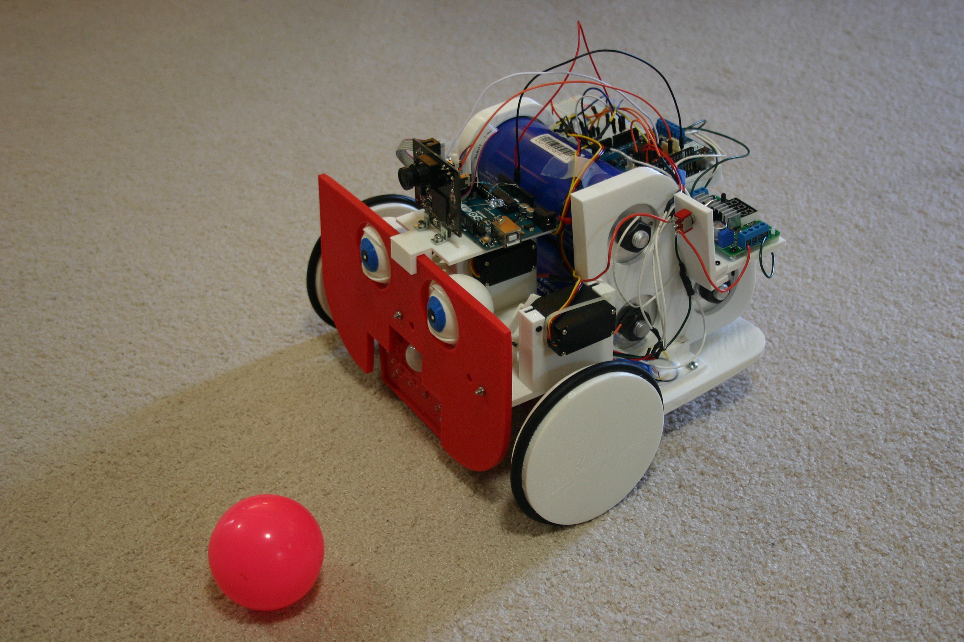
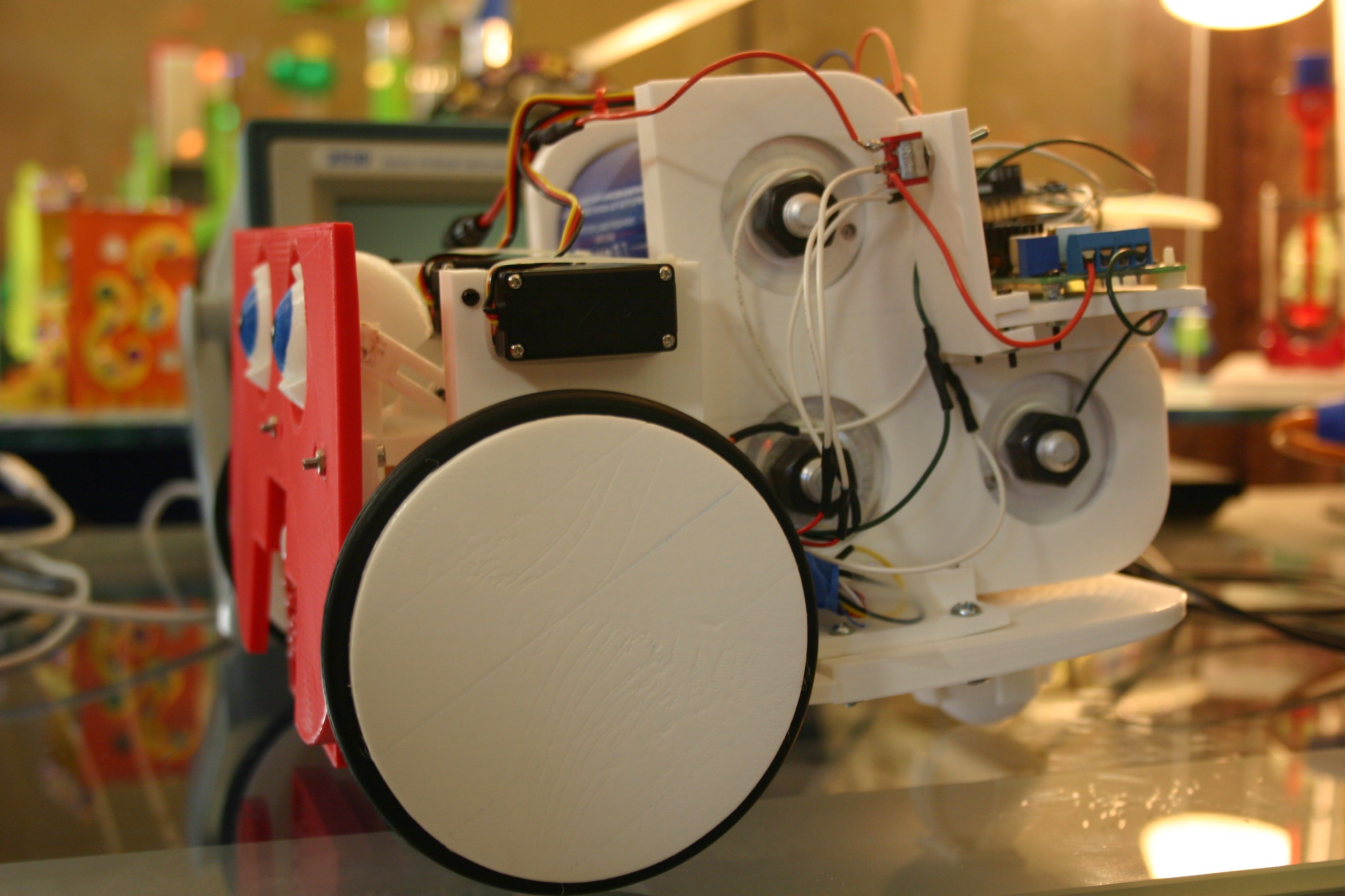
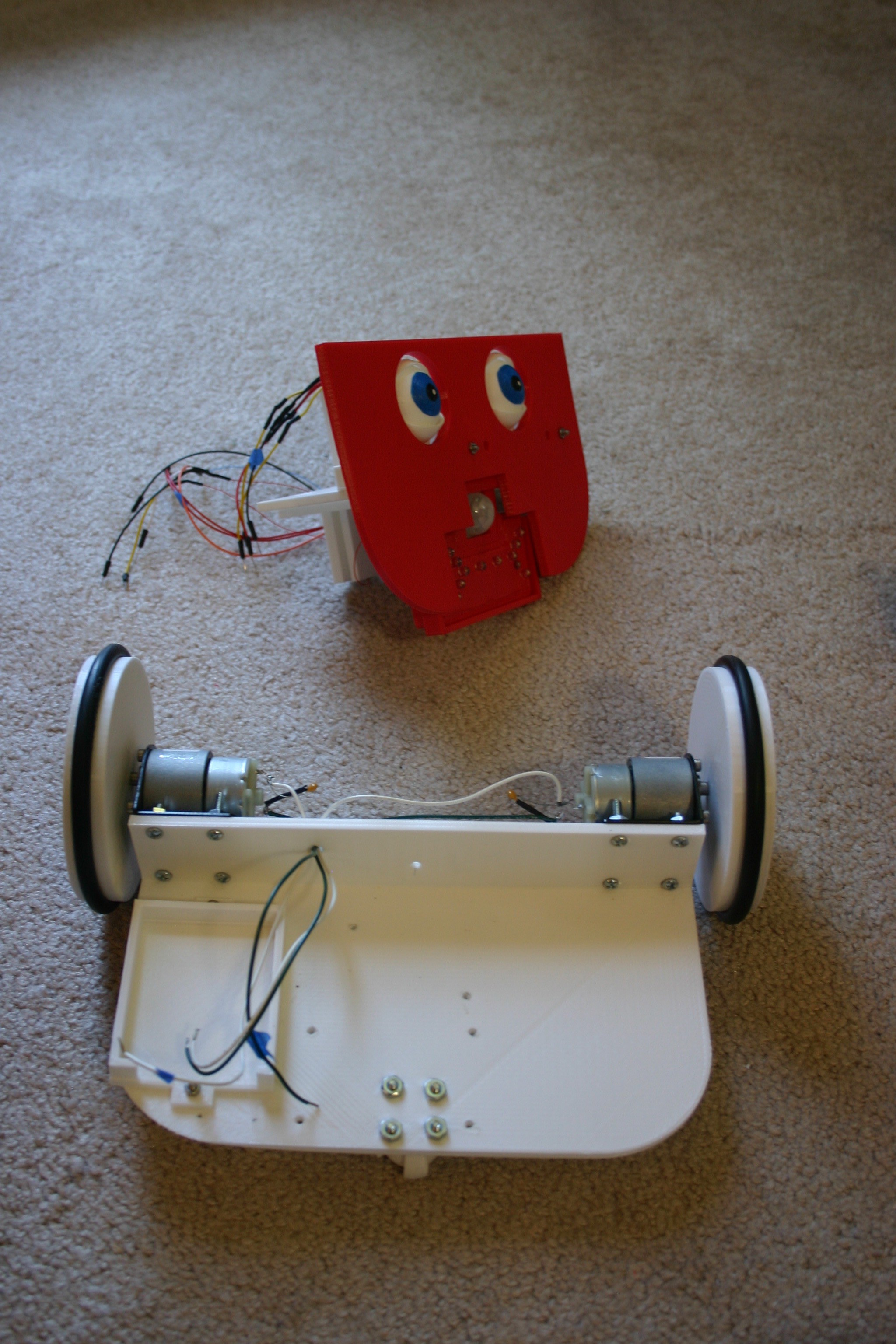
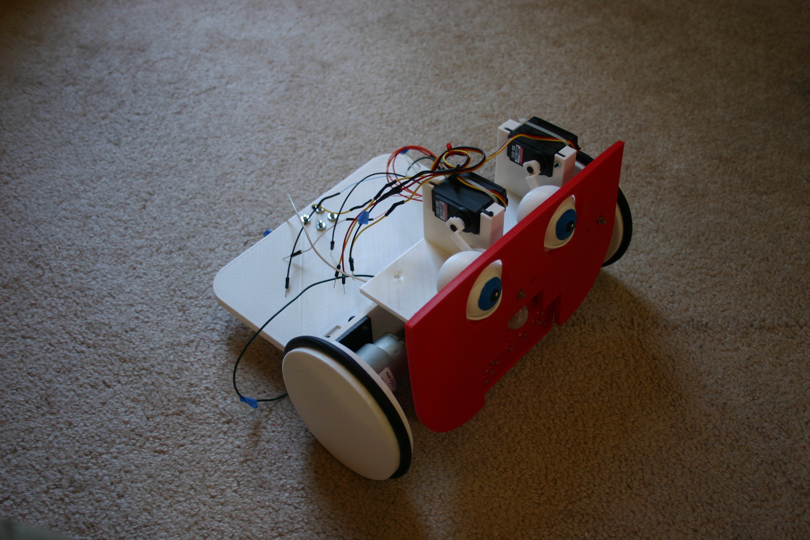
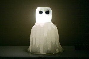
As much as I like the look of wires, gears and micro-controllers, Little Friend needs a better "look" to work for normal people. My wife will help with the artistic side.
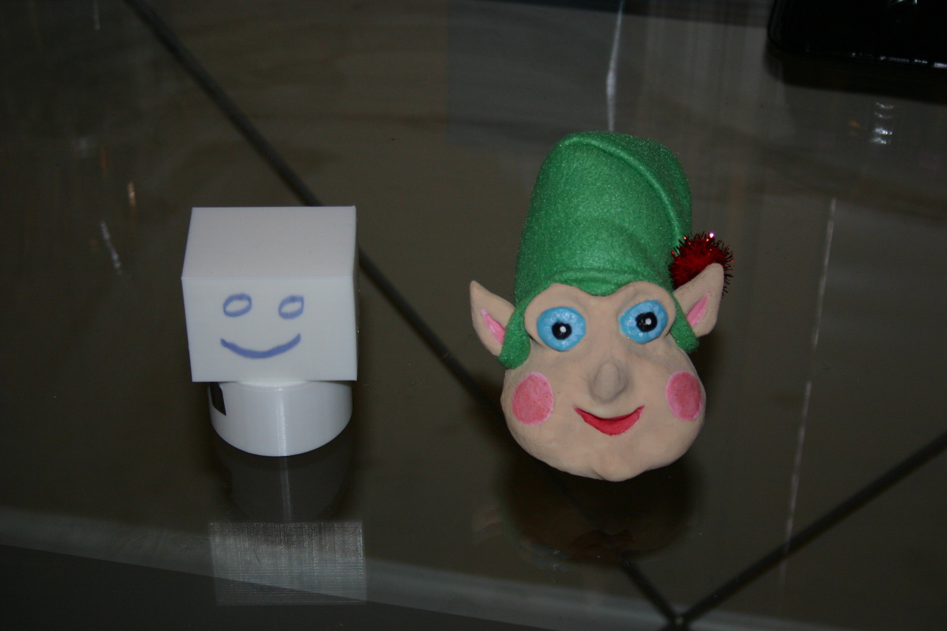 For example, above on the left is my idea of a head while above on the right is her translation of what I wanted.
Challenges will include cost (capacitors and charger), power consumption, feature creep, stair avoidance and features like eyes or a head.


 Tom Nardi
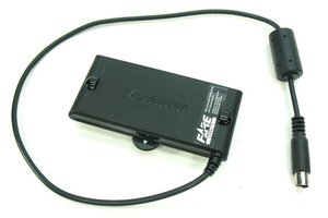
 Rebelj12a
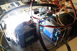
 Bryan Howard
I actually think this is pretty cool. It's like a roomba meets a furby.