 Clovis Fritzen
Sooo basically I want to challenge myself into building a radio-controlled toy from scratch. I am more inclined to electronics than mechanics, so I decided that the mobile mechanical platform would be just any one I can put my hands on. Now the electronics are of my interest!.
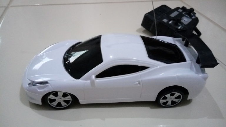
I bought the RC toy car above for around US$5 (actually R$30 in Brazil) as a first platform for tests.
I confess that I am not a RC hobbyist myself, so I have never had contact with any aspect of that world. I didn't really know how an ESC (electronic speed controller) worked before starting this project; so I decided I would implement every line of code of this project without looking at anything already available on the market.
That means I would try to make everything (code, hardware) from scratch; what a challenge!.
The first step was to define which microcontroller platform to use on the project; of course I decided for Arduino (haha!), mainly because I own a bunch of ATMEGA328's and also because I currently run a blog on embedded systems ( www.FritzenLab.com.br ) and use Arduino as the core and for most articles.
Second step was to assemble a (half-functional) mechanical prototype of the circuit boards, just to have a feeling of the size and look/feel of it. Pictures are below for both the emitter (radio controller) and the receiver (motor controller).
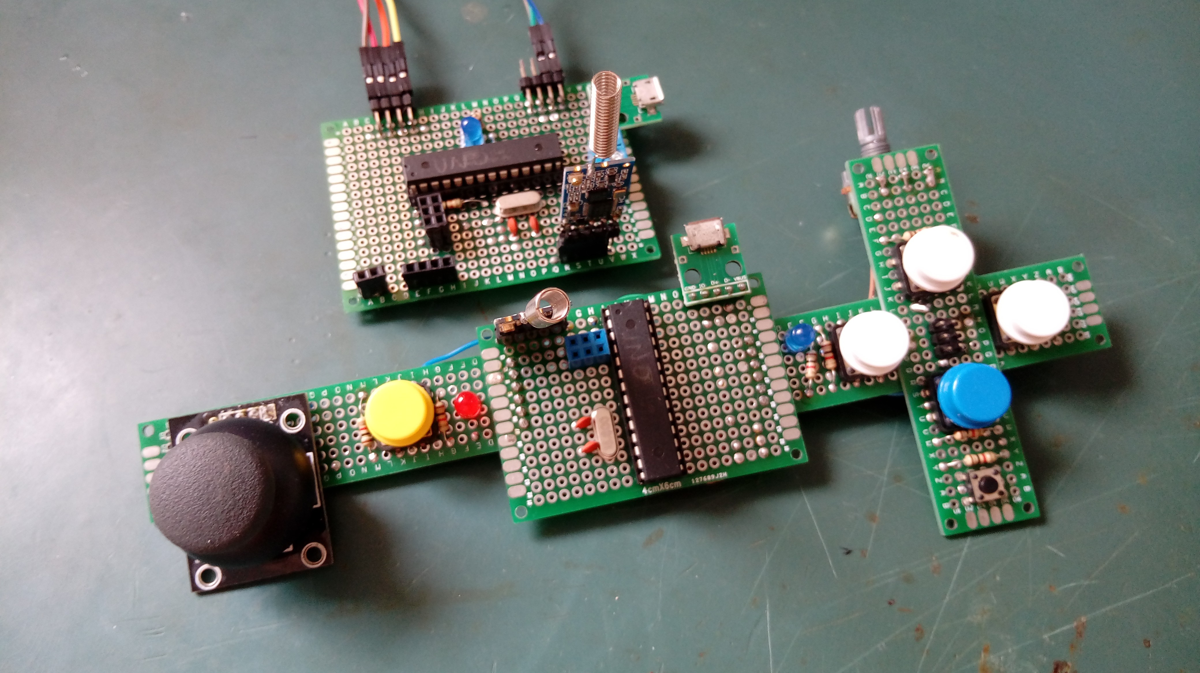
From the picture you can see a bunch of details of the hardware, but never forget all files (Eagle, Fritzen, Arduino code) are hosted in this Github.
The emitter (controller) features:
- One true analog X-Y joystick
- Six push buttons
- Two LED's (outputs)
- One analog potentiometer (for analog trimming)
- Pin header for radio (I plan to test and use most-likely the 433Mhz HM-10)
- USB connector for power
The receiver (motor controller) features:
- Eight IO's (Inputs or outputs) from ATMEGA328 (Arduino UNO)
- Pin header for radio (I plan to test and use most-likely the 433Mhz HM-10)
- USB connector for power
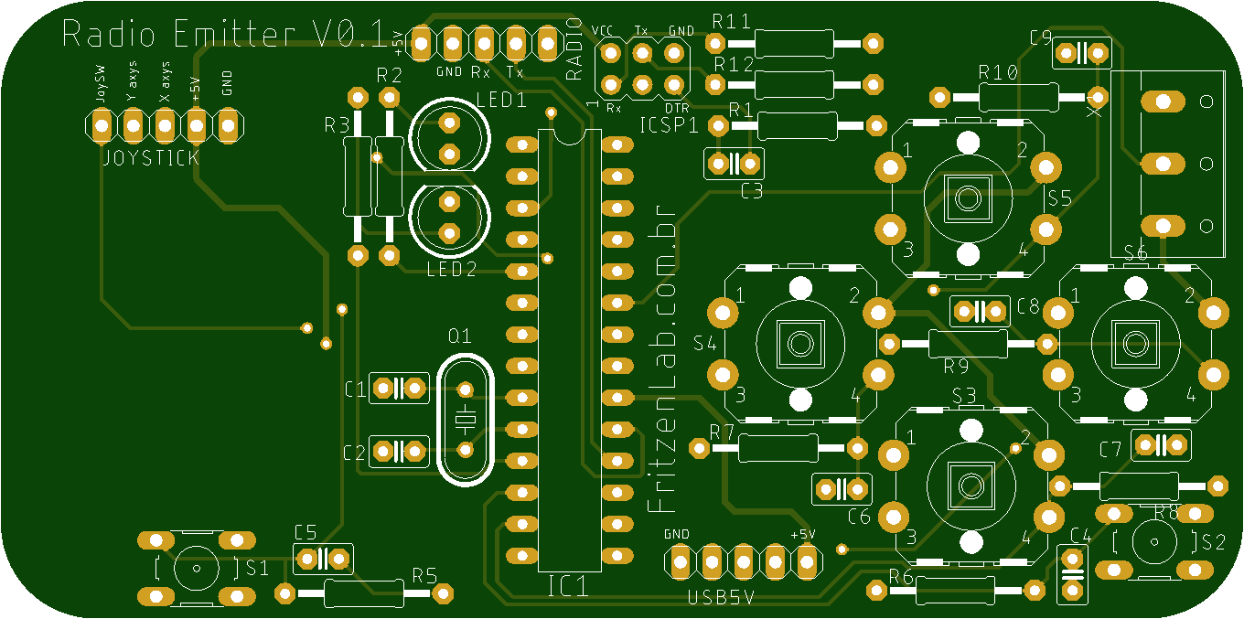
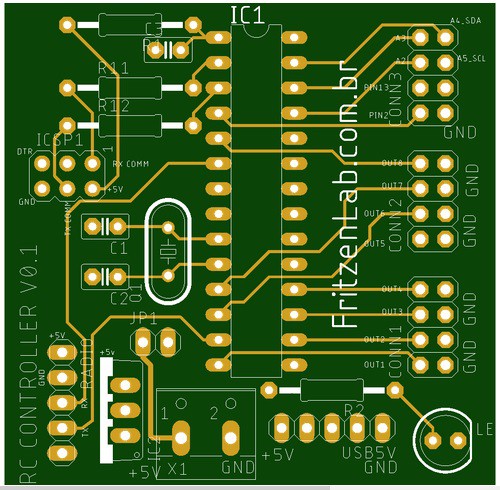
Third step was to draw schematic diagram and PCB for the prototypes. I did it in a couple of hours using Eagle CAD and some Adafruit and Sparkfun libraries. Results can be seen below.
This project is an ongoing thing, I don't even have the code to test it. At the moment I am waiting for prototype PCB's to arrive from JLCPCB China (this thing take 2-3 months to arrive in Brazil, seriously).
 UTSOURCE
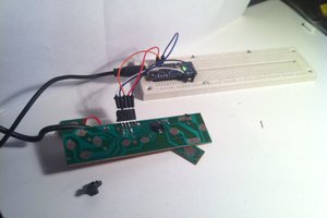
 zvodd
zvodd
 Zeke Barsan
Creating a DIY remote controller for RC vehicles using an Arduino UNO and 433MHz modules is a fun project that allows you to customize your control system. Here's a basic guide to get you started: all the project details are also present at Jazz Internet Packages https://jazzinternetpackages.pk/
**Materials Needed:**
1. Arduino UNO (or compatible board)
2. 433MHz transmitter and receiver modules (e.g., FS1000A and XY-MK-5V)
3. Joystick module
4. Push buttons (for additional controls)
5. Breadboard and jumper wires
6. RC vehicle (with compatible receiver)
**Step 1: Setting up the Transmitter (Remote Controller)**
1. Connect the 433MHz transmitter module to your Arduino UNO:
- VCC to 5V
- GND to GND
- Data pin to a digital pin (e.g., Pin 12)
2. Connect the joystick module to the Arduino UNO:
- VCC to 5V
- GND to GND
- X-axis to analog pin A0
- Y-axis to analog pin A1
3. Optionally, you can add push buttons for additional controls:
- Connect one terminal of each push button to a digital pin (e.g., Pins 2, 3, etc.)
- Connect the other terminal of each push button to GND
**Step 2: Programming the Transmitter**
Here's a basic example code to read joystick inputs and transmit them via the 433MHz module:
```arduino
#include <VirtualWire.h>
#define JOYSTICK_X A0
#define JOYSTICK_Y A1
void setup() {
vw_set_ptt_inverted(true); // Required for 433MHz modules
vw_setup(2000); // Bits per sec
pinMode(JOYSTICK_X, INPUT);
pinMode(JOYSTICK_Y, INPUT);
}
void loop() {
int xValue = analogRead(JOYSTICK_X);
int yValue = analogRead(JOYSTICK_Y);
// Map joystick values to desired range (if needed)
// int mappedX = map(xValue, 0, 1023, 0, 255);
// int mappedY = map(yValue, 0, 1023, 0, 255);
// Send joystick values as bytes
byte data[2] = {byte(xValue), byte(yValue)};
vw_send(data, 2);
vw_wait_tx(); // Wait until the whole message is gone
delay(50); // Adjust as needed for transmission rate
}
```
**Step 3: Setting up the Receiver (RC Vehicle)**
1. Connect the 433MHz receiver module to your RC vehicle's Arduino:
- VCC to 5V
- GND to GND
- Data pin to a digital pin (e.g., Pin 12)
2. Connect the output pin of the 433MHz receiver module to the input pin of your RC vehicle's receiver module.
**Step 4: Programming the Receiver (RC Vehicle)**
The receiver code will receive the joystick inputs and pass them to the RC vehicle's motor controllers. This code will depend heavily on your specific RC vehicle setup and motor control mechanisms. You'll need to interface with your RC vehicle's existing code or create new code to interpret the incoming signals and control the vehicle accordingly.
With these steps, you should be able to create a basic DIY remote controller for your RC vehicle using an Arduino UNO and 433MHz modules. Make sure to customize the code and connections according to your specific requirements and RC vehicle setup. Happy tinkering!