Dillon Nichols
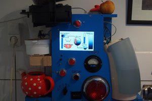
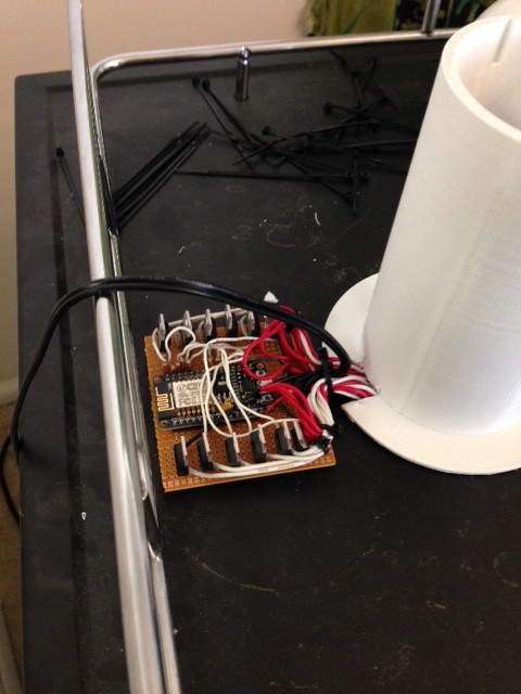
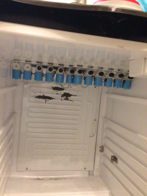
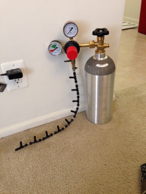
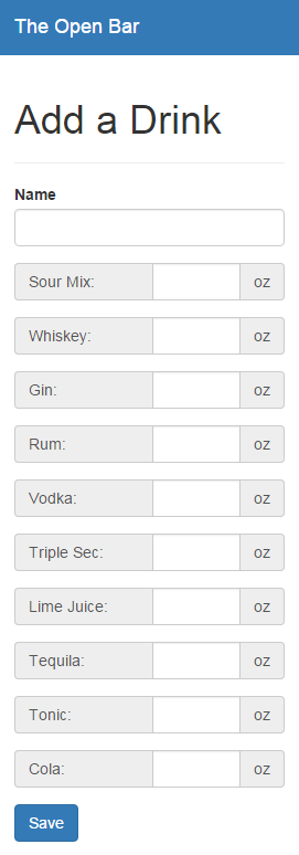
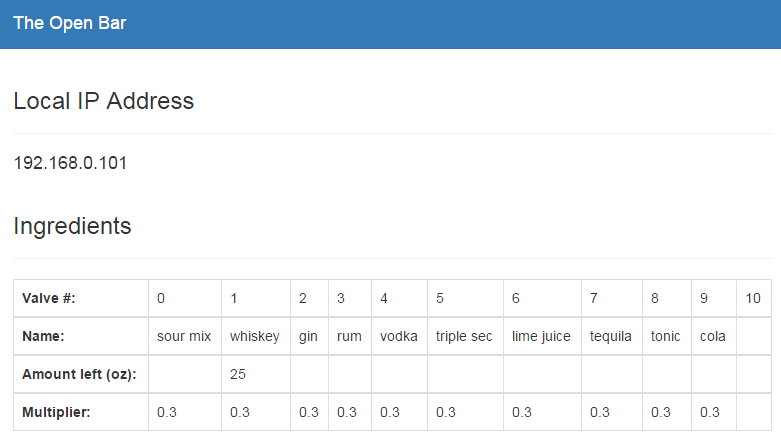
There are two sides to this project. The hardware side consists of a small refrigerator/kegerator or a cooler (can you say portable bar), solenoid valves, a vacuum pump, mixing chamber, and a custom PCB for output control. A python program running on a Raspberry Pi 3 controls all of the hardware logic. The software side is a web app created using the MEAN stack (MongoDB, ExpressJS, AngularJS, NodeJS) that allows the user to access all of the available recipes and select the drink that they want to pour. The server hosting the MEAN stack, communicates to the python control program via a TCP socket connection. This allows flexibility for it to be hosted on the same Raspberry Pi 3 device, or an independent server hosting several dispensing machines.
We’ve created a “beta” version of the project that proves that our idea is possible. We’ve even poured a few drinks! Check out the initial pour on YouTube. In the process, we have discovered that our pouring mechanism could use some work, so we redesigned the method to create a reproducible platform. Here is the new approach in action:
Once the hardware is more stable, we will post instructions so anybody can create their own “The Open Bar”. In the meantime, please use the comment system on this page to post feedback.
Source code is available at https://github.com/theopenbar/
This project is licensed under the GNU General Public License v3.0
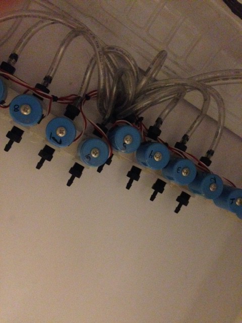
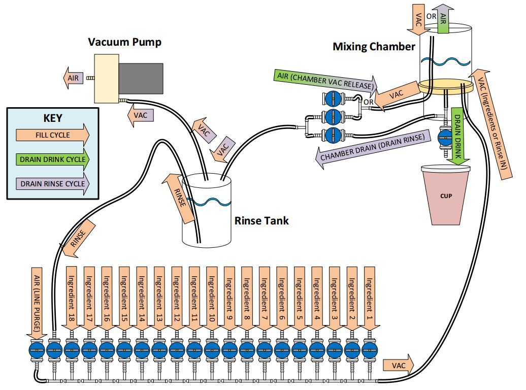 To pour a drink, there are essentially 4 steps, using 3 different flows or "cycles". These cycles are identified in the diagram as the "Fill Cycle", "Drain Drink Cycle", and "Drain Rinse Cycle". The different cycles represent different states of the blue solenoid valves, creating different flows in the system. To elaborate, let me walk you through a complete drink pouring process.
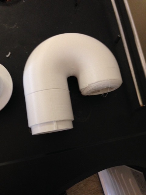
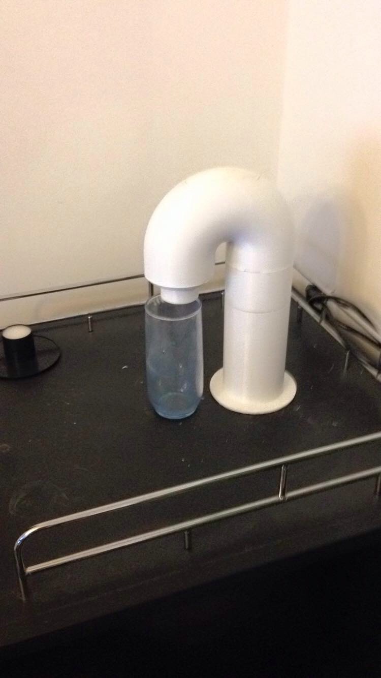
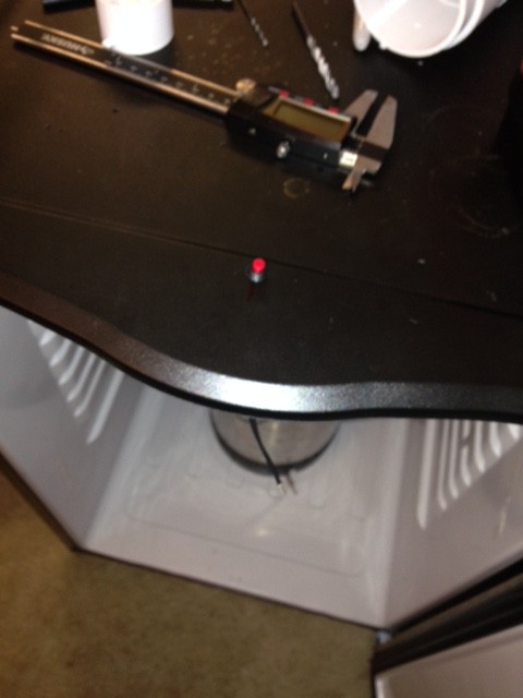
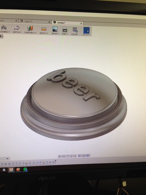
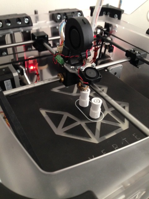
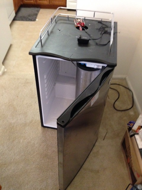 The first thing we designed was a 3D-printed spout that could lock into the hole already manufactured into the kegerator top. Here are some pictures of that:
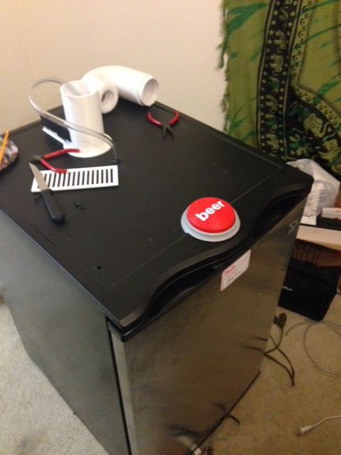


 Chuck Buckley
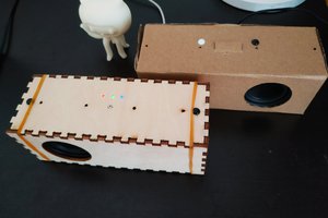
 Yihui
Yihui
 RodolpheH