 Tyler
TylerFor The Open Bar hardware design, we started off with a simple approach. For the first iteration of the project, the idea was to use a CO2 tank to pressurize the ingredients that would be dispensed. Each one of the ingredients would have 2 hoses -- a pressurized hose from the CO2 tank regulator going in, and a hose from the bottom of the bottle going out to a solenoid valve. From the valve, another hose would go to the faucet of the drink machine. In this way, each ingredient would have a separate path, and to add more ingredients you just needed to add a valve and hose.
To control the valves, we tried using a cheap ESP8266 wifi module. In our application, the ESP module implemented a simple HTML server. The user GUI, implemented on another device in a web browser, would send a HTML "GET" request, passing a GPIO number and a number of milliseconds as parameters. The ESP module would then activate the specified GPIO for that amount of time. Each GPIO was connected to a TIP120 NPN Power Darlington Transistor through a resistor. The transistors provided open-drain current sinks, acting as switches for the solenoid valves. The valves were powered by a 12V rail supplied by an AC/DC power adapter.
Although the ESP worked as a controller, there were several limitations. One limitation was the number of GPIOs available. There were about 10 usable GPIOs on our ESP board. This gave us 10 possible valves for ingredients. There was a catch, however. On power-up, some of these GPIOs have specific pull-up and pull-down requirements. This led to some funky valve activation occurring anytime the ESP module was restarted. The solution was adding a switch to the 12V rail supplying the solenoid valves. This way, the valves could only be activated when the system was "armed" (when the 12V switch was turned on).
To dispense an amount of an ingredient, the valve would be activated for a calibrated amount of time. In theory, this approach sounded easy and simple to implement. This was the approach used in this initial setup:
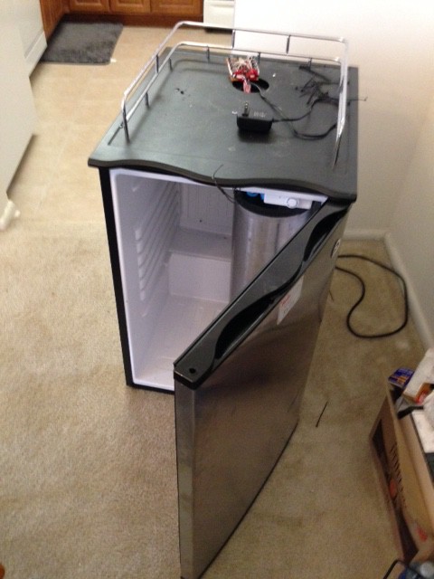
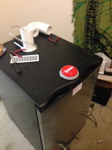
The following photos are a quick overview of our first design. Our initial concept was to retrofit a kegerator. The kegerator would serve as the storage place for all the connected ingredients. This is the kegerator with a small ball-lock type keg inside, popular with home-brewers:
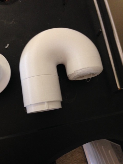
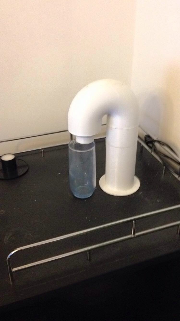
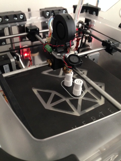
 The first thing we designed was a 3D-printed spout that could lock into the hole already manufactured into the kegerator top. Here are some pictures of that:

This picture shows a close-up of the piece of the faucet which held the end of the hoses in place. They were simply pushed into the holes, which were slightly smaller in diameter. The piece itself fit into notches inside the end of the faucet.

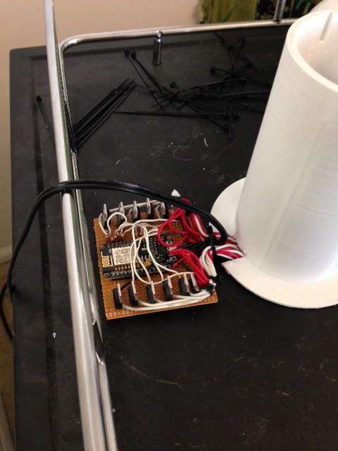
The ESP8266 and TIP120s were wired up on a small proto-board that was mounted at the rear of the faucet:
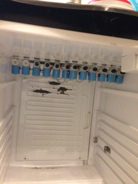
The valves were all mounted inside the kegerator on the ceiling for tube routing convenience:
As you can see here, the tubing was a tight fit to get through the hole with the wires: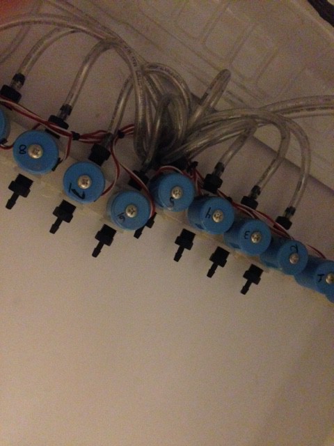
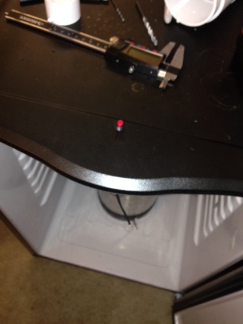
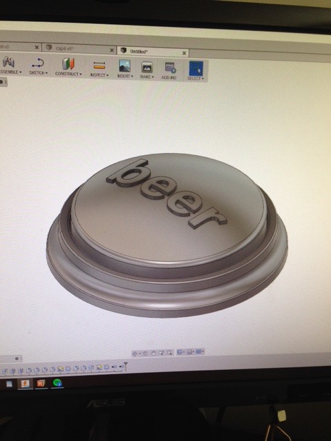
We chose to also have beer cooled in our kegerator. Since beer isn't mixed with anything we didn’t need to have beer dispensed automatically by the machine. For fun though, we made it dispense with the push of a button, where the button directly activated a valve for the keg. Here are some photos of the installation of the button. The 3D printed part was simply spot glued to the small red push-button I had lying around:

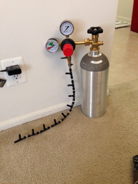
Here we have the CO2 tank and regulator. The pressure lines to the different ingredients were simply 'T' connections to the main output:
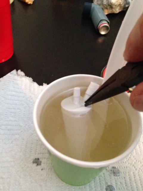
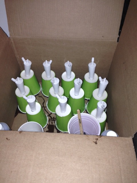
And then the main trouble we encountered, the bottle stoppers, are shown here. They were first 3D printed, then covered in a food-safe acrylic for strength and to make them air-tight. The outer surface had a molded covering of food-safe silicon to try and seal the 4PSI of pressure provided by the CO2 tank.
Here is the stopper before being coated in acrylic. The center, smaller barbed fittings are for the liquid and run through the piece as a solid pipe. A hose is attached to the bottom barb to extend to the bottom of the bottle. The pressurized gas line connects to the larger, angled fitting. The gas enters the bottle around the barbed fitting at the bottom of the stopper: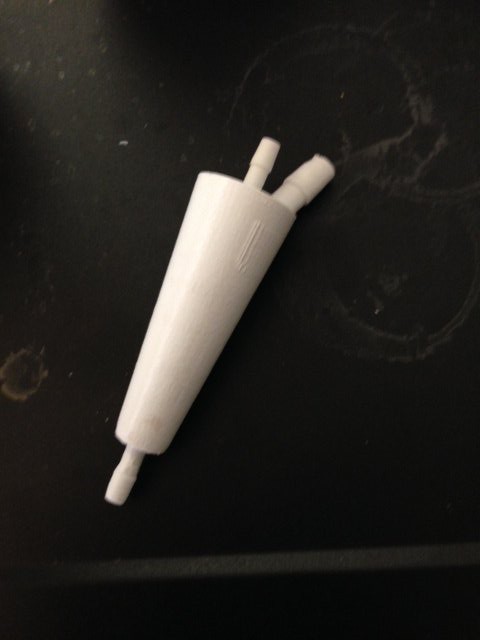
The approach worked, but there were several disadvantages and difficulties so we decided we needed to make some changes. We could only route hoses from 10 separate bottles in our setup, so this seriously reduced our system’s capability of making a large number of cocktails. The biggest problem, however, was coming up with a universal cap system that could be used on any bottle that was quick and easy to attach. Our attempt at a 3D printed stopper-like device with barbed ports for the hoses did not work. The problem was that we underestimated how easily the 4PSI used to pressurize the bottles could remove a cork.The silicon was too soft to provide a tight hold to keep the stopper from popping off the bottle. The CO2 was useful for keeping soft drinks carbonated, but a lot of CO2 would be wasted on ingredients that don't require carbonation, such as the liquors. This trouble, along with the aim to make the system as easy to make as possible for others, led us in a new direction.
The result was a complete redesign of the dispensing system and controller. The goals for the new design would be to use a vacuum system so that the bottles would not need to be pressurized and could be connected by just inserting one hose. The pressurized capability could still be used for special purposes such as 2-liter soda bottles, where a special cap could be used. Thus, carbonation would be preserved while providing a secure seal. Another aim was to minimize the requirement of any 3D-printed objects, since many people might not have access to such equipment. For revision 2, we wanted to use common DIY hardware and techniques as much as possible, while leaving room for creative implementation for those who would like to try their own implementation.
Part 2 will talk about the new Hardware Design.
Discussions
Become a Hackaday.io Member
Create an account to leave a comment. Already have an account? Log In.