 krich
krichGosh, I'm not sure how much I can say about this little circuit that hasn't been said a million times over on the internet in dozens of languages. This is simply a "use a transistor to activate a relay" circuit.
I'm no electrical engineer, but I will attempt to explain the circuit.
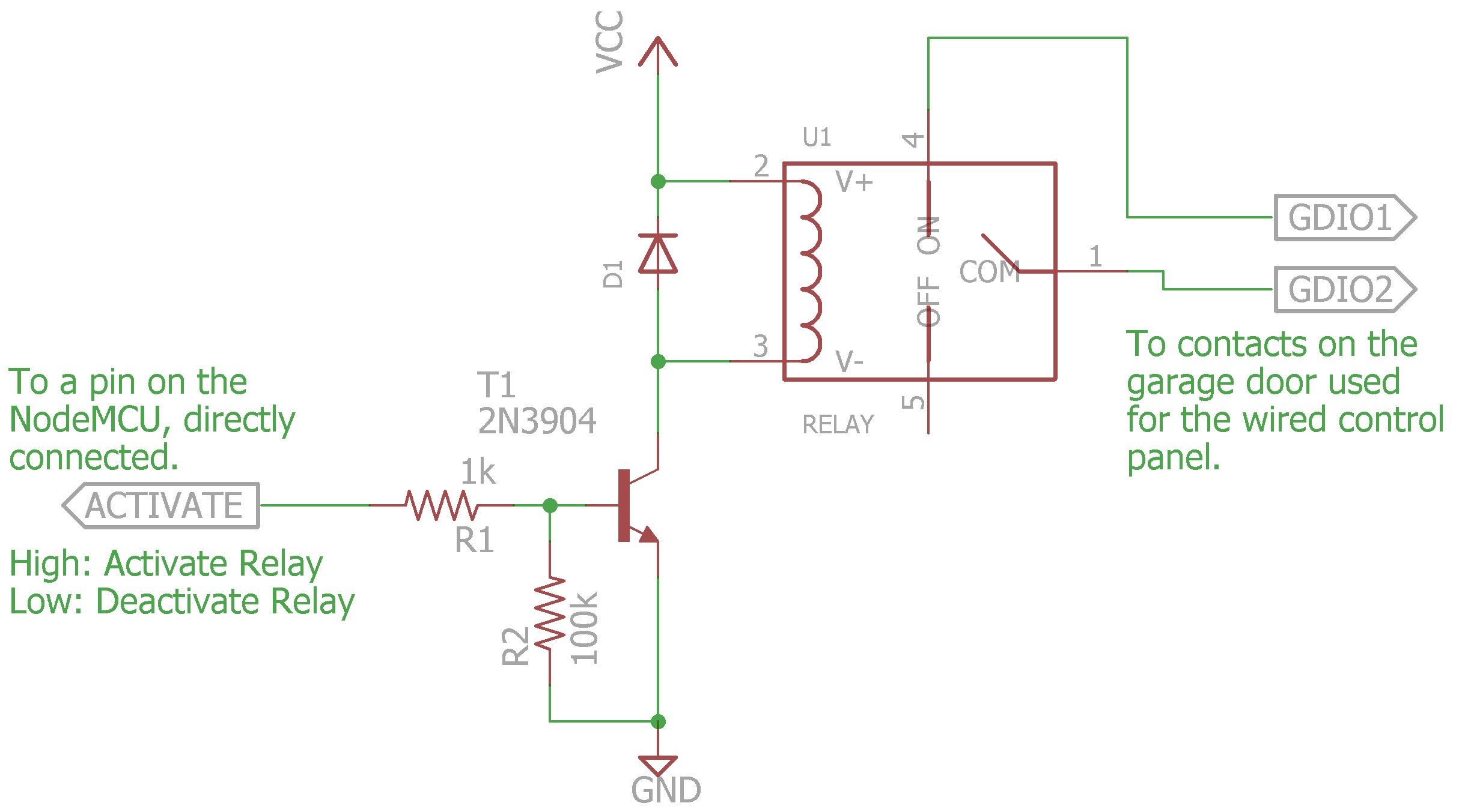
The basis of this circuit is to find a way to activate a relay which requires 12v or better to activate with a pin on the ESP8266 which is only at 3v. This is where the transistor comes in.
The transistor is being driven so that it is essentially a switch, that is to say it is either on or off and rarely in between. When the pin on the ESP8266 is driven high (3v), the current through the base (side) turns on the transistor between the collector (top) and the emitter (bottom).
The resistor connected to the ESP8266 pin (activate) is there to limit the current to reasonable levels so that you don't blow out the IO pin on the ESP8266. The larger value resistor connected to the ground reference keeps the circuit in line and essentially deactivated when or if the ESP8266's pin is floating.
Because the coil in the relay is an inductive load, it can (and likely always will) generate a high voltage spike as the electromagnet inside the relay turns off. The diode gives that spike a better path to dissipate than through the transistor, thus saving the transistor from an almost certain and unpleasant fate.
And finally, when the relay activates, it connects the two GDIO1 and GDIO2 terminals together, which is what activates the garage door.
And, while I'm at it and even though I'm sure it's pretty obvious, I guess I should mention that this circuit to activate the garage door is operated as a "pulse", similar to a button push. That means to activate the garage door, you set the ESP8266 pin high, wait a second, then set it low again. Just like a button push. You push it and then let it go.
Next I think I'll post about the power supply I used for the NodeMCU (for which I was written up in Hack a Day quite a while back, and, yes, I am still doing it). Stay tuned.
Happy hacking!
Discussions
Become a Hackaday.io Member
Create an account to leave a comment. Already have an account? Log In.